Astro Pneumatic Tool PRN2 User manual

Product Type:Model: PRN2 1/2" CAPACITY AUTOMATIC RIVET NUT
SETTING KIT - METRIC & SAE
Page 1
Study, understand and follow all instructions provided
with this product. Read these instructions carefully
before installing, operating, servicing or repairing this
tool. Keep these instructions in a safe accessible place.
INTENDED USE OF THE TOOL
This tool intended to be used to set M5-M12 and
10-24"-1/2" aluminum and steel rivet nuts. Operate only
at the require air pressure necessary. Do not over-set
rivet nuts. Do not use this tool outside of the designed
intent. Never modify the tool for any other purpose or use.
Caution: To help prevent personal injury
• Use of this product can expose you to chemicals
such as phthalates which are known to the State
of California to cause cancer, and birth defects or
other reproductive harm. For more information go
to www.P65Warnings.ca.gov/product.
Always wear ANSI approved safety equipment,
safety glasses and clothing when using this
product. Study, understand, and follow all
instructions provided with this product. Failure to
read and follow all warnings and operating
instructions may result in damages and serious
injury or death.
• Always wear ANSI approved goggles when using
this product. (Users and By standers).
• Never use this tool for any application other than for
which it was designed.
• Only use accessories designed for this tool.
• Never alter or modify this tool in any way.
• Improper operation and/or maintenance of the tool,
modification of the tool, or use of the tool with
accessories not designed for it could result in
serious injury or death.
• Always select the correct accessories of the correct
size and design for the job that you are attempting to
perform.
• Always work in a clean, safe, well-lit, organized and
adequately equipped area.
• Do not begin repairs without assurance that vehicle
is in secure position, and will not move during repair.
WARNING
WARNING
www.astrotools.com
1 YEAR LIMITED WARRANTY
PLEASE DO NOT RETURN ANY PRODUCT WITHOUT CALLING
1-800-221-9705 FOR INSTRUCTIONS
PRODUCT INFORMATION
BEFORE USE
DO NOT DISCARD – GIVE TO USER
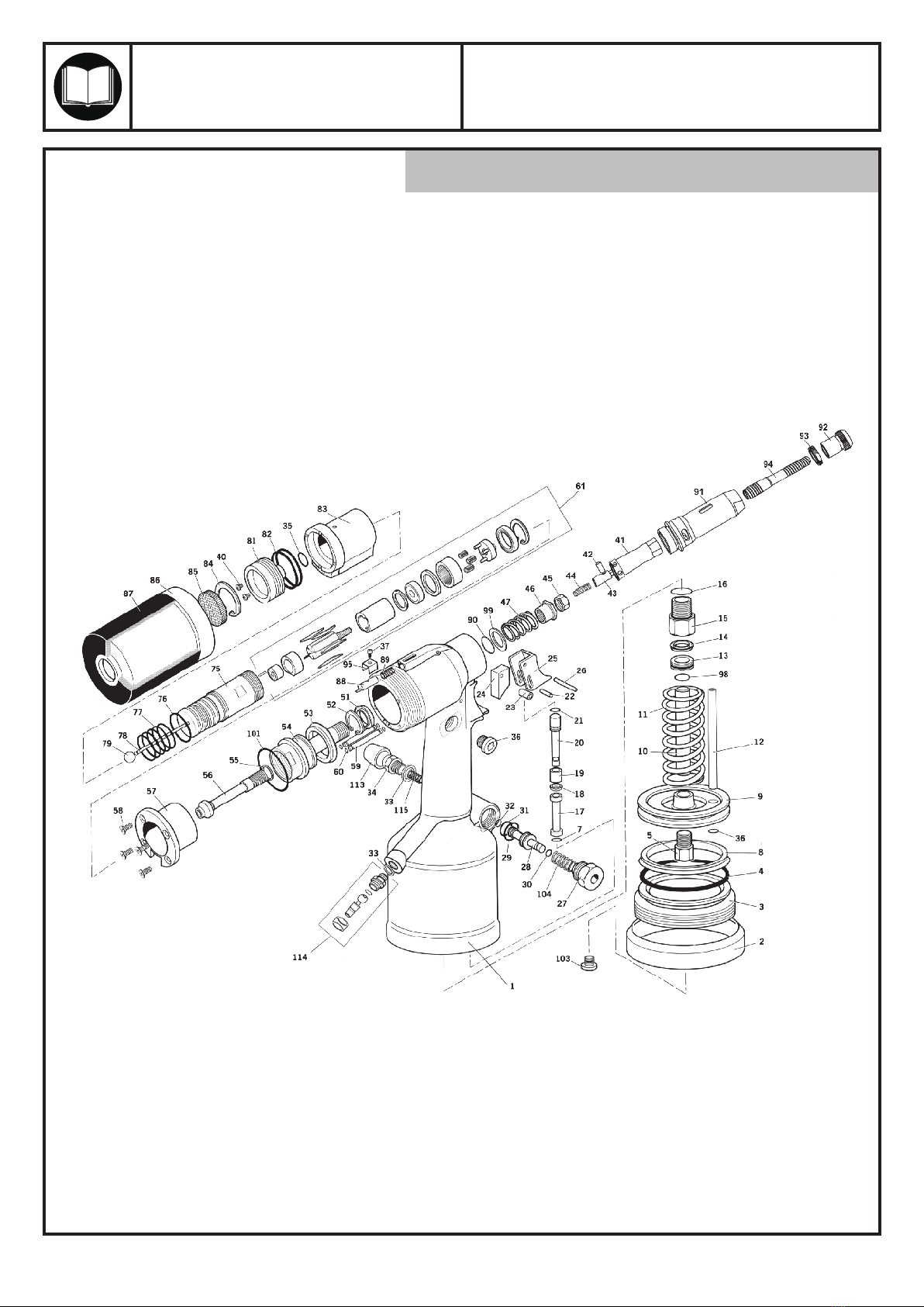
When unpacking, check the parts diagram and part
number listing on page 5 to make sure all parts are
included. If any parts are missing or damaged,
please call your distributor.
• Astro Pneumatic Tool Co. warrants our products to the original user
against defective material or workmanship for a period of 1 year
(except where noted on our price schedule) from the date of 1st use.
Astro reserves the right to determine whether the product failed
because of defective material, workmanship or other causes and to
charge back for missing parts. Astro Pneumatic Tool Co., at its
discretion, will repair products covered under this warranty free of
charge. The distributor should direct the original user to return the
product (with the exceptions listed below) with the distributor’s
name, address, adequate proof of date of purchase or a copy of
warranty card, and a short note explaining the problem. Failures
caused by accident, alteration, or misuse are not covered by
this warranty.
• If one part of this product fails, please do not return the entire
product. Astro will replace free of charge component parts of
this product that fail within 1 year of first use by the original
user. Items included in this category include but are not limited
to kits, hand tool kits and any other product where there are
multiple items or components that make up the unit. Please
contact the phone number below in order to obtain the
replacement components covered under warranty.
• Astro Pneumatic Tool Co. or its authorized service representatives
must perform all warranty repairs. Any repair to the product by
unauthorized service representatives voids this warranty. The rights
under this warranty are limited to the original user and may not be
transferred to subsequent owners.
• This warranty is in lieu of all other warranties, expressed or implied,
including warranties of merchantability and fitness for a particular
purpose. Some states do not allow the exclusion of limitations of
incidental or consequential damages so the above limitations may
not apply to you.
• Fully automated operation. One pull of the trigger
sets and unthreads the tool from rivet nuts up to
M12 and 1/2"
• Includes 10 mandrels / nosepieces in the following sizes:
M5, M6, M8, M10, M12, 10-24, 1/4", 5/16", 3/8", 1/2"
• 4270 lbs of instant air-hydraulic pulling force
• Up to 7mm of adjustable stroke length, set by rotating
the rear drum to your desired stroke setting
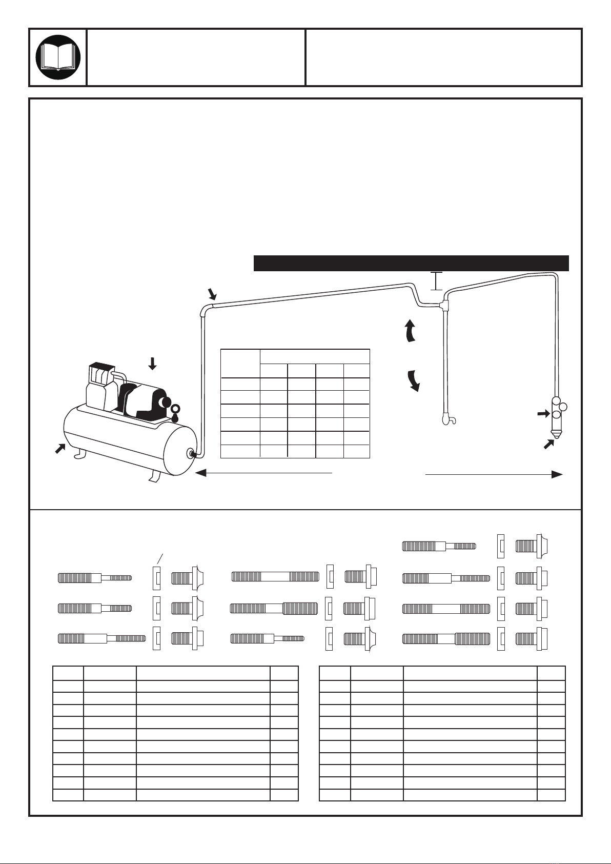
Traction Power:
Tool Stroke:
Work Capacity:
Air Inlet:
4270 lbs of force
7mm max
1/2"
1/4" PT
Specification:

Product Type:Model: PRN2 1/2" CAPACITY AUTOMATIC RIVET NUT
SETTING KIT - METRIC & SAE
Page 2
PRIMING
CHANGING MANDRELS
STROKE ADJUSTMENT
PRIMING PROCEDURE
Priming is ALWAYS necessary after the tool has been dismantled and prior to operating. It may also be
necessary to restore the full stroke after considerable use, when the stroke may be reduced and fasteners
are not fully placed by one operation of the trigger.
OIL DETAILS
The recommended oil for priming is mineral oil based hydraulic oil like Castrol Hyspin VG 32 or other.
• Place tool on its side, oil plug 42 side up.
• Pull back stroke set finger 88 and unscrew rear casing 86 by a maximum of 5 turns from the fully 'IN' position.
• With an Allen key, unscrew oil plug 42 and remove with oil seal washer 43.
• Fill tool with priming oil rocking gently to expel air.
• Replace oil seal washer 43 and oil plug 42 and tighten.
• You must now bleed screw 48 is fully tightened unscrew by ONE TURN only, using an Allen key.
Connect the tool to the air supply and depress the trigger.
• Wait until oil appears all around oil bleed screw 48 then re-tighten. Wipe excess oil away.
• Release the trigger.
• Using an Allen Key open oil plug 42.
• Top-up with priming oil to reset level. Replace oil seal washer 43 and oil plug 42 and fully tighten.
• It is necessary to fit the appropriate nose equipment and adjust the tool stroke prior to operating the tool.
Item numbers in bold refer to general assembly drawings and parts list. (Pages 5-6).
Release lock and rotate rear drum to adjust applied stroke to the rivet nut, up to 7mm.
To change mandrel, remove this nose
cover then push back the roll pin in the
window by hand.
This releases the hex drive into the
mandrel for easy unthreading.

Product Type:Model: PRN2 1/2" CAPACITY AUTOMATIC RIVET NUT
SETTING KIT - METRIC & SAE
Page 3
WARNING
MAINTENANCE INSTRUCTION
1.) LUBRICATION:
Before connection of the hose, apply 4 to 5 drops
of a good quality air tool oil at the air inlet.
After 3 to 4 hours of operation, oiling may be
necessary again.
2.) TIGHTNESS OF PARTS:
Regularly check whether all connecting parts are
fastened securely. Follow this procedure daily
before beginning work.
3.) STORAGE:
Avoid storing the tool in a location subject to high
humidity. If the tool is left unused, the residual
moisture inside the tool can cause rust. Before
storing and after operation, oil the tool at the air
inlet with a good quality air tool oil and run it for
a short period.
4.) DISPOSAL:
Follow national legislation of waste disposal.
5.) ORDERING SERVICE PART:
For further operational and handling information
or for replacement of parts and components,
contact the sales agent from where you purchased
the tool, or the service division of our company,
phone number 800-221-9705.
* When ordering parts and components, give each
part number, name, and quantities.
Users of this tool should review the chemical
composition of the work surface and any products
used in conjunction with this tool for any such
chemicals prior to engaging in any activity that creates
dust and/or microscopic particles.
Users should obtain the Material Safety Data
Sheets for all identified chemicals, either from the
manufacturer or their employer, and proceed to study,
understand, and follow all instructions and warnings
for exposure to such chemicals.
Some examples of these chemicals are: lead from
lead based paints; crystalline silica from bricks,
cement and other masonry products; and arsenic and
chromium from chemically treated lumber. A listing of
the chemicals can be obtained at
www.oehha.ca.gov under Propoisition 65.
In order to reduce their exposure to such chemicals,
users should always:
- work in well-ventilated areas.
- wear appropriate safety equipment and clothes that
are specifically designed to filter out microscopic
particles.
1. The tool shall not be used in potentially explosive
atmospheres.
2. Disconnect the air hose before changing or adjusting
any inserted tools.
3. Before using tool, please confirm all couplings and
plugs are fixed securely. An air hose that is under
pressure may lash out when disconnected and could
lead to serious injuries.
4. Prevent loose clothes, long hair or any other personal
accessories from coming close to moving parts to
reduce the risk of being caught, trapped or drawn into
the rotating spindle.
5. Excessive high air pressure that exceeds the maxi-
mum pressure may cause injuries to user.
6. Exposure to strong vibration for extended time may
cause harm to operator.
7. Be aware of the rotation direction before starting the
tool to reduce hazardous situations due to unexpected
rotation direction.
8. WATCH YOUR STEP! Leaving excess hose unattend-
ed near working area or walk path could result in
injury or death.
9. Wearing eye/face protection could reduce the danger
to person from high speed splinters being emitted
from the tool or work surface.
10. Wearing correct breathing protection will help avoid
inhaling dust or debris from work process that can be
harmful to your health.
11. High sound levels can cause permanent hearing loss.
Use hearing protection while operating tool.
12. Due to the material being processed, there may be a
risk of explosion or fire. Be aware of work surface
dangers prior to beginning work.
13. There is a risk of being cut due to high speed rotation.
Do not touch high speed rotating disc.
14. This power tool is not insulated. If contact is made with
an electric current, injury may occur.
15. Dust created by sanding, sawing, grinding, drilling and
other related activities may expose the user to dust
and/or microscopic particles that may contain chemi-
cals known to the State of California to cause cancer,
birth defects or other reproductive harm.

MANDRELS / NOSEPIECES PARTS LIST
Product Type:Model: PRN2 1/2" CAPACITY AUTOMATIC RIVET NUT
SETTING KIT - METRIC & SAE
Page 4
SUGGESTED AIR LINE CONNECTION
Pitch pipe back toward air receiver
Compressor unit
Drain
Daily 25 FEET OR MORE
Oil and Water Extractor should be at least 25 ft. from the compressor. Further if possible.
Drain Daily
Drain
Daily
Oil and Water
Extractor
Install drain at
each low point
PIPE SIZE, I.D. (Inches)
Air Flow
CFM
Length of Pipe (feet)
10
20
30
40
50
70
50
1/2"
3/4"
3/4"
1"
1"
1"
100
3/4"
3/4"
3/4"
1"
1"
1"
150
3/4"
3/4"
1"
1"
1"
1-1/4"
200
3/4"
1"
1"
1"
1-1/4"
The oil and water extractor should not be mounted on
or near the air compressor.
The temperature of air is greatly increased during
compression. As the air cools down to room
temperature, in the air line, on its way to the Air Power
Tool, the moisture contained in it condenses. Thus, for
maximum effectiveness, the oil and water extractor
should be mounted at some point
in the air supply system where the temperature of the
compressed air in the line is likely to be lowest. Air
lines must be properly drained daily. Each low point in
an air line acts as a water trap. Such points should be
fitted with an easily accessible drain. See diagram
below. Pitch all air lines back towards the compressor
so that condensed moisture will flow back into the air
receiver where it can be drained off.
Drain daily.
1
6
7
8
9
10
11
12
13
14
15
16
17
18
19
20
21
2
3
4
5
Qty
1
2
3
4
5
6
7
8
9
10
PRN2-116
PRN2-117
PRN2-118
PRN2-119
PRN2-120
PRN2-121
PRN2-122
PRN2-123
PRN2-124
PRN2-125
M5 Mandrel
M6 Mandrel
M7 Mandrel
M10 Mandrel
M12 Mandrel
10-24" Mandrel
1/4" Mandrel
5/16" Mandrel
3/8" Mandrel
1/2" Mandrel
Index Part No. Description
1
1
1
1
1
1
1
1
1
1
11
12
13
14
15
16
17
18
19
20
21
PRN2-126
PRN2-127
PRN2-128
PRN2-129
PRN2-130
PRN2-131
PRN2-132
PRN2-133
PRN2-134
PRN2-135
PRN2-136
M5 Nosepiece
M6 Nosepiece
M7 Nosepiece
M10 Nosepiece
M12 Nosepiece
10-24" Nosepiece
1/4" Nosepiece
5/16" Nosepiece
3/8" Nosepiece
1/2" Nosepiece
Sleeve
1
1
1
1
1
1
1
1
1
1
10

Product Type:Model: PRN2 1/2" CAPACITY AUTOMATIC RIVET NUT
SETTING KIT - METRIC & SAE
PARTS BREAKDOWN Call 1.800.221.9705 for questions concerning performance of the product
or other inquiries.
Page 5

Product Type:Model: PRN2 1/2" CAPACITY AUTOMATIC RIVET NUT
SETTING KIT - METRIC & SAE
Call 1.800.221.9705 for questions concerning performance of the product
or other inquiries.
Page 6
Parts List
Qty
1
2
3
4
5
7
8
9
10
11
12
13
14
15
16
17
18
19
20
21
22
23
24
25
26
27
28
29
30
31
32
33
34
35
36
37
40
41
42
43
44
45
46
47
PRN2-01
PRN2-02
PRN2-03
PRN2-04
PRN2-05
PRN2-07
PRN2-08
PRN2-09
PRN2-10
PRN2-11
PRN2-12
PRN2-13
PRN2-14
PRN2-15
PRN2-16
PRN2-17
PRN2-18
PRN2-19
PRN2-20
PRN2-21
PRN2-22
PRN2-23
PRN2-24
PRN2-25
PRN2-26
PRN2-27
PRN2-28
PRN2-29
PRN2-30
PRN2-31
PRN2-32
PRN2-33
PRN2-34
PRN2-35
PRN2-36
PRN2-37
PRN2-40
PRN2-41
PRN2-42
PRN2-43
PRN2-44
PRN2-45
PRN2-46
PRN2-47
Head & Handle
Rubber Base
End Plug (Screwed)
O-Ring
Piston Rod Fastening Bolt
O-Ring
Lip Seal (Pneumatic Piston)
Pneumatic Piston
Piston Rod (Intensifier)
Spring
Air Supply Tube
Lock Nut
Seal
Rod Guide
O-Ring
Plug
Lip Seal
Guide
Trigger Rod
O-Ring
Pin
Roller
Push Wedge
Tirgger
Pin
Valve Locking Plug
Valve Piston
O-Ring
O-Ring
O-Ring
O-Ring
1/8" Nylon Washer
1/8" Slencer
O-Ring
Oil Plug
M4 Socket HD Screw
M4 Button Socket HD Screw
Spindle
Pin
Hexagon HD Locknut
Spring
Lock Nut
Return Spring Locknut
Return Spring
Index Part No. Description
1
1
1
1
1
1
1
1
1
1
1
1
1
1
1
1
1
1
1
1
1
1
1
1
1
1
1
1
1
1
1
2
1
1
1
1
2
1
1
1
1
1
1
1
Qty
51
52
53
54
55
56
57
58
59
60
61
75
76
77
78
79
81
82
83
84
85
86
87
88
89
90
91
92
93
94
95
98
99
101
103
104
105
106
107
109
113
114
115
Front Seal
Circlip
Seal
Hydraulic Piston
Shim Adjustment Ring
Movement Pivot
Stroke Stop
M5 CSK Socket Head Screw
Pneu Motor Air Supply Tube
O-Ring
Air Motor Assembly
Air Motor Casing
O-Ring
O-Ring
Push Rod 80mm Long
Ball (Rubber)
Air Motor End Plug
O-Ring
Distrunutor
Circlip
Sintered Silencer
Rear Casing
Rear Casing Rubber Band
Stroke Set Finger
Spring
Locking Ring
Nose Casing
Nose Tip
Nose Tip Lock Nut
Thread Rod
Bridge Washer
O-Ring
Washer
O-Ring
Plug
Spring
Tool Manual
17mm Thin Spanner
19mm Thin Spanner
5mm Allen Key
Deflector Assembly
Inlet Assembly
Spring
Index Part No. Description
PRN2-51
PRN2-52
PRN2-53
PRN2-54
PRN2-55
PRN2-56
PRN2-57
PRN2-58
PRN2-59
PRN2-60
PRN2-61
PRN2-75
PRN2-76
PRN2-77
PRN2-78
PRN2-79
PRN2-81
PRN2-82
PRN2-83
PRN2-84
PRN2-85
PRN2-86
PRN2-87
PRN2-88
PRN2-89
PRN2-90
PRN2-91
PRN2-92
PRN2-93
PRN2-94
PRN2-95
PRN2-98
PRN2-99
PRN2-101
PRN2-103
PRN2-104
PRN2-105
PRN2-106
PRN2-107
PRN2-109
PRN2-113
PRN2-114
PRN2-115
1
1
1
1
1
1
1
4
2
4
1
1
1
5
1
1
1
2
1
1
1
1
1
1
1
1
1
1
1
1
1
1
1
1
1
1
1
1
1
1
1
1
1
Table of contents
Other Astro Pneumatic Tool Rivet Tools manuals
Popular Rivet Tools manuals by other brands

Berner
Berner BPT-BR 4-8 Instruction manual/safety instruction

Silver Eagle
Silver Eagle SE200 operating instructions

Blue Pneumatic
Blue Pneumatic BP-20CR instruction manual

BGS technic
BGS technic BGS 3284 instruction manual

Ingersoll-Rand
Ingersoll-Rand 9001 Product information

Huck
Huck ALCOA POWERIG 913H instruction manual