Titgemeyer RIVETEC RL 75 User manual

Riveting Tool
RL 75
Operating Manual

2
Table of contents
Guiding instructions........................................................... 4
Cautions, instructions and procedural
sections in the operating instructions ................................... 5
Markings on the riveting tool ................................................ 6
Safety instructions ............................................................. 7
Basic requirements while dealing with
the riveting tool .................................................................... 8
Noise and vibration levels of the RL 75................................ 10
Description of the riveting tool ......................................... 10
Necessary tools.................................................................. 12
Storing the riveting tool/ tension heads........................... 13
Preparing the riveting tool................................................. 14
Select tension head .............................................................. 16
Assemble tension head ........................................................ 17

3
Operating the riveting tool................................................. 21
Set locking ring bolt .............................................................. 21
Setting the blind rivet ............................................................ 22
Maintaining the riveting tool.............................................. 23
Bleeding the hydraulic section.............................................. 23
Refilling hydraulic oil............................................................. 24
Table for torque values ......................................................... 26
Riveting tools/ Tension heads service and cleaning....... 27
Maintenance intervals ........................................................ 28
Trouble shooting................................................................. 29
Disposal of the riveting tool.............................................. 31
Technical data..................................................................... 31
Declaration of conformity .................................................. 35
Guarantee , Package Contents .......................................... 33

4
Guiding instructions
The legislator prescribes that the user must be well trained for using com-
pressor-driven riveting tools. On request, this training could be done by
dealer or directly by RIVETEC s.r.o.
This riveting tool is as per the latest technological standards. For the
device to function properly, it is necessary to operate it in an expertly
manner, with adherence to safety requirements.
Before using the riveting tool for the first time, read the guiding instruc-
tions carefully.
All the procedures necessary for the operation have been described in
these guiding instructions. You may carry out only those procedures,
which have been described here.
In case of obstructions, you may repair only those obstructions, which
have been marked with an O(Operator).
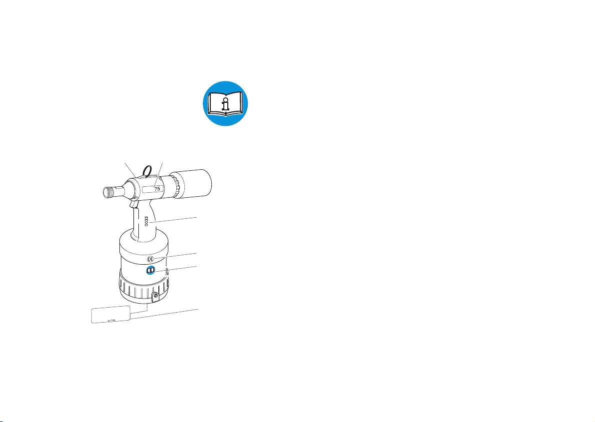
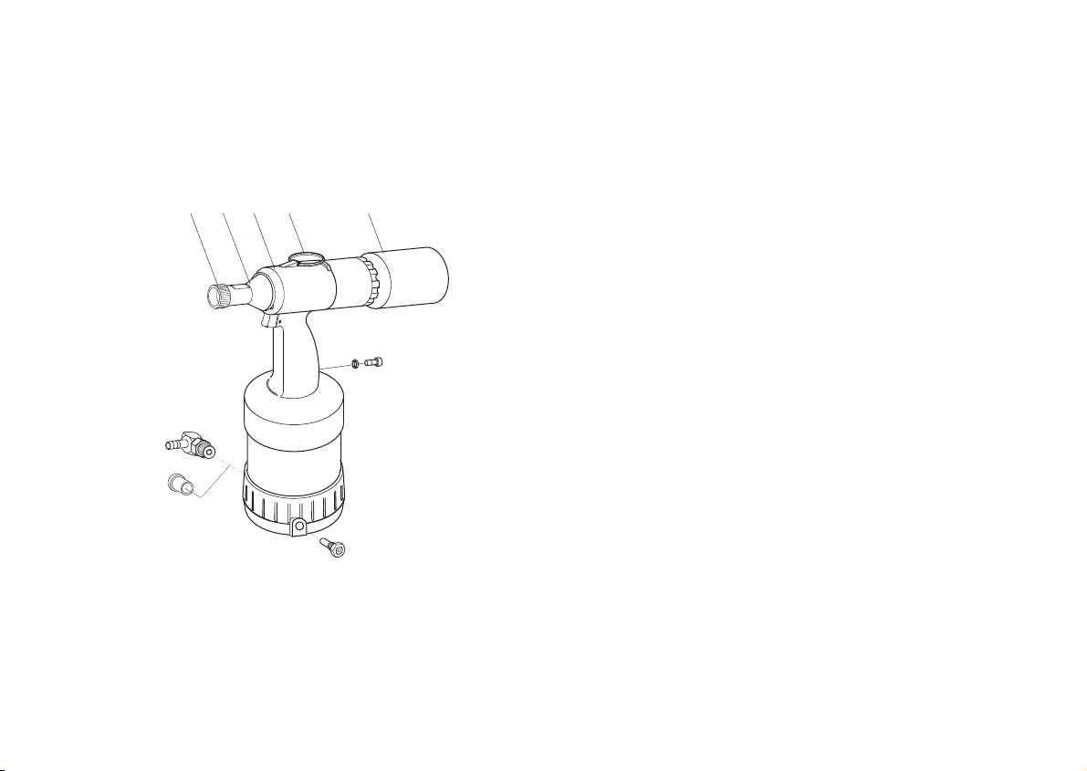
All the illustrations and position-codes in the individual diagrams take
reference from the list of parts in the last pages.
For sizes of screws and threads, you will find a table containing the torque
values in the chapter “Maintaining the riveting tool”.
Instruction
Technological level
Reading the guiding instructions
Procedures
Obstructions
Illustrations and position-codes
Table for torque values

5
Guiding instructions
Cautions, instructions and procedural sections in the
operating manual
Please follow the instructions and safety informations.
In this operating manual, some sections have been further illustrated
through diagrams.
Please acquaint yourself well with these diagrams and their meanings:
Caution Hazard of injury! This marking indicates a potential hazard.
Attention Material damage! This marking points at a procedure, which
may cause damage to the riveting tool or the work-piece.
Note This marking indicates useful information
• This point (•) marks every paragraph, which requires you to act by
yourself.
Attention Environmental hazard! This marking indicates a potential
environmental hazard.
H
E
Environmental
hazard

6
Guiding instructions
Markings on the riveting tool
This pictogram indicates that you must read the operating manual before
using the riveting tool.
A Marking of the type
B Serial number
C CE-marking
D Instruction for reading the operating manual
F Name of the manufacturer and the value of the maximum operating
pressure
G Supplier RIVETEC
A
B
F
G
RL
75
C
D

7
Safety instructions
The riveting tool is solely designed for setting locking ring bolts and blind
rivets. The riveting tool RL 75 is designed for the processing of locking
ring bolts with a nominal shaft diameter of 5.0 to 6.5 mm made of alumini-
um, steel and stainless steel and for blind rivets with a rivet shaft diameter
of 5.0 to 6.5 mm made of aluminium, steel and stainless steel.
This riveting tool must be used only as a hand-held device!
The client is fully responsible for any modifications to the riveting tool!
Never throw away or drop the riveting tool!
Please take care that only clean and dry compressed air is let into the
riveting tool. Moisture and dirt can damage the riveting tool. Use only such
compressed air, which falls into class 2 of air quality as per ISO 8573-1.
Caution Hazard of injury because of explosion! Never use the riveting
tool in an atmosphere prone to explosions. Ensure that the
workplace is well lit and clean.
Hazard of injury due to the openly moving compressed air
hose. Connect and lay the compressed air hose properly.
Hazard of injury due to tripping over! Lay the compressed air
hose in such a way that nobody should trip over it.
Attention Material damage! The maximum operating pressure is 7 bar.
For increasing the durability of the riveting tool, it is recommen-
ded to fit a compressed air-maintenance unit in the compressed
air hose.
Application as per the purpose
Improper use
Clean and dry compressed air
H
E

8
Safety instructions
Basic requirements while dealing with the riveting tool
Caution Do not operate the riveting tool when it is directly pointing at
any person.
Follow the prevalent guidelines for the prevention of accidents
in the respective country.
Use only those fittings and hoses, which have been approved
for the operating pressure.
Disconnect the compressed air supply from the riveting tool at
the time of installation or maintenance.
Wear personal safety gear (safety glasses and safety helmet).
Attention Pay attention to the details on the packaging of the blind rivets
or locking ring bolts.
Use the riveting tool only at operating temperatures above 5°C
and 45°C.
Always use the fitting tension head for every type of blind rivet,
locking ring respectively.
Do not throw away the riveting tool.
The operator may only carry out the maintenance and repair work descri-
bed in these operating instructions.
Maintenance and service work not described in these operating instruc-
tions may only be carried out by trained specialists following instruction by
RIVETEC on the basis of the service instructions which also exist. See the
address on page 34 for more information on service instructions and
training.
H
E
Maintenance and servicing
Service instructions

9
Note The manufacturer accepts no liability for damage resulting from
incorrect repairs or the use of spare parts from other sources.
At the time of leaving the workplace, do not leave the riveting tool with
pressure on.
A guarantee is void, if any repair work carried out on the riveting tool has
lead to any damage of the riveting tool.
The riveting tool RL 75 has been checked and manufactured according to
European guidelines. The declaration of conformity can be found on the
second last page.
Noise and vibration levels of the RL 75
The sound-emission level for workplaces is LPAI<70dB(A) as per
ISO 10843 and DIN EN 3744.
The effective value measured on acceleration with the handle, as per
ISO/FDIS 8662-11, is ahw<2,5m/s2.
Guarantee
Declaration of conformity
Noise level
Vibration level
Safety instructions

10
Description of the riveting tool
The riveting tool RL 75 works according to a pneumatic-hydraulic
prinziple.
It consists of the following operation-related components:
1Knurled nut fixes the tension head
2Nose cap covers jaw case body
3Hydraulic the pneumatic and the hydraulic
housing units are located in the hydraulic housing
4Hang-up eyelet for hanging up on a hook whenever stationary
6Collector collects the torn off mandrel, tension part res-
pectively
2346
1

11
11
13
9
10
7
8
Note The socket head screw (7) and the O-ring (8) are screwed tightly
into the grip. The socket head screw (7) must not be loosened,
else the hydraulic oil will leak.
7Socket locking for the hydraulic oil system
head screw
8O-Ring sealing of the hydraulic oil system
9Safety valve (Brass) In case of very high pressures (approx.
8 bar or more), it opens, and lets the air out
10 Plug serves the purpose of protection of the thread
and also against dirt
11 Swivel- serves as the connection for compressed air
joint hoses (operating pressure 6 bar)
13 Trigger when activated, the riveting procedure starts
Description of the riveting tool

12
Necessary tools
You will require the following tools for all installation, servicing and mainte-
nance work. The tools SW13, SW9/16'', SW17, SW22 can be ordered.
Tools
— Crank (16)
— Internal hex key
— Wrench
1No delivery possibility
16
SW4 SW13 SW9/16'' SW17 SW22
(17)
SW4(17)
SW131, SW9/16''1, SW171, SW221

13
11
10
6
Storing the riveting tool/ tension heads
Until first use
If you do not intend to use the riveting tool immediately, store the riveting
tool and the tension heads in their original packaging - in a dry and dust-
free condition.
Long-term storage after usage
Turn collectors (6) off, screw out swivel joint (11) and close the opening
with the plug (10). Dismantle tension head and lubricate with acid-free
grease. If possible, store all pieces in the original packing.
After long-term storage
After long-term storage (about 3 years), change the hydraulic oil before
re-use.
A hydraulic oil change may only be carried out by trained specialist with
the help of the service instructions. For further information regarding
service instructions and training, please see the address on page 34.

14
Preparing the riveting tool
The components ordered by you are marked as per the checklist found
inside the packing.
Note Please check the contents of the packing, for completeness of
the checklist
In every case, please carry out a visual check of the riveting tool before
starting any work:
— for external damages,
— for oil leakage from the riveting tool.
• Remove the plug (10) from the connection port, and store in the original
packing.
Note The swivel joint (11) and the safety valve (9) can be alternative-
ly fitted on both the sides of the hydraulic housing. The diagram
below shows the arrangement for a right-hander.
Note In case of all screw-fittings, observe the table for torque values
in the chapter “Maintaining the riveting tool”
• Screw on the swivel joint (11) and tighten using the wrench SW17 (see
page 26 “Table for torque values”).
10
9
11
11
9
Package insert

15
Preparing the riveting tool
E
Note Depending on the type of compressed air supply, it may be
necessary to connect a fitting different from the one provided,
to the riveting tool. For this, you need to have a fitting having a
1/4” Withworth pipe thread as per ISO 228.
Attention Material damage by compressed air!
As per norm ISO 8573-1, class 2, compressed air must be dry
and clean. We recommend that you fit a compressed air-main-
tenance unit to the riveting tool.
• Compressed air hose should be connected to the swivel joint (11), as
prescribed.
Note The operating pressure must be between a minimum of 5 and a
maximum of 7 bar!
11

Type Ø* Material Tension head Assembly
Lock. ring bolt C106/ C6L 5.0 Alu./ steel/ stainless steel 99-2555 Page 17
6.0/ 6.5 Alu./ steel/ stainless steel 99-2561
MAGNA-GRIP 5.0 Alu./ steel 99-1456 Page 17
6.5 Alu 99-1458
Tainer 6.5 Steel 99-3465 Page 20
Blind rivet MAGNA-LOK and 5.0 Alu./ steel/ stainless steel 99-3303 Page 18
MAGNA-BULB 6.5 Alu./ steel/ stainless steel 99-3305/ 06
BOM 5.0 Steel 99-994 Page 19
* Blind rivet: Rivet shaft diameter; locking ring bolt: Nominal shaft diameter
16
Select tension head
You can modify the riveting tool to process locking ring bolts and blind rivets of varying sizes and materials by
changing the tension head. If a different tension head has already been mounted, dismantle it in compliance
with the assembly description in reversed sequence.
Always check the tension head before every assembly for outer damages. The tension heads have to be
ordered separately.
You can see which tension head is to be used from the following table.
Preparing the riveting tool
16
The tension head 99-3465 (Tainer) can only be mounted to the MS 75 by means of a special nose cap that has
to be ordered separately (see “list of parts” on page 33).

17
Preparing the riveting tool
Mount tension head (99-1456; 99-1458; 99-2555; 99-2561)
Before mounting the tension head, make sure that you have chosen the
right tension head (see table on page 16).
The assembly is identical for the tension heads listed.
The tension head 99-2561 is displayed in the illustrations.
• Loosen compressed air connection.
• Screw (2) nose cap off.
• Insert O-Ring (C) with slotted screw driver in the groove on the jaw case
body (12) (O-Ring (C) is included with the tension head).
• Grease O-Ring (C) and thread on the jaw case body (12) lightly with
acid-free grease (Vaseline).
• Screw jaw case (B) onto the jaw case body (12) and tighten at a torque
of 12 Nm.
• Slip nose cap (2) without knurled nut (1) over the jaw case (B), screw
into the hydraulic housing (3) and tighten at a torque of 20 Nm.
• Slip tension head case (A) over the jaw case (B) and push into the nose
cap (2) up to the limit.
• Slip knurled nut (1) over the tension head case (A), screw onto the nose
cap (2) and screw hand tight.
12
C
2
B
A
C
12
3
1
2

Preparing the riveting tool
18
Mount tension head (99-3303; 99-3305; 99-3306)
Before mounting the tension head, make sure that you have chosen the
right tension head (see table on page 16).
The assembly is identical for the tension heads listed.
The tension head 99-3303 is displayed in the illustrations.
• Loosen compressed air connection.
• Screw (2) nose cap off.
• Insert O-Ring (C) with slotted screw driver in the groove on the jaw case
body (12) (O-Ring (C) is included with the tension head).
• Grease O-Ring (C) and thread on the jaw case body (12) lightly with
acid-free grease (Vaseline).
• Screw nose piece (M) tension head case (A) and tighten at a torque
value of 5 Nm.
• Screw jaw case (B) onto the jaw case body (12) and tighten at a torque
of 12 Nm.
• Slip nose cap (2) without knurled nut (1) over the jaw case (B), screw
into the hydraulic housing (3) and tighten at a torque of 20 Nm.
• Slip tension head case (A) over the jaw case (B) and push into the nose
cap (2) up to the limit.
• Slip knurled nut (1) over the tension head case (A), screw onto the nose
cap (2) and screw hand tight.
12
C
2
C
B
A
M
12
3
1
2

19
Preparing the riveting tool
Mount tension head (99-994)
Before mounting the tension head, make sure that you have chosen the
right tension head (see table on page 16).
• Loosen compressed air connection.
• Screw (2) nose cap off.
• Insert O-Ring (C) with slotted screw driver in the groove on the jaw case
body (12) (O-Ring (C) is included with the tension head).
• Grease O-Ring (C) and thread on the jaw case body (12) lightly with
acid-free grease (Vaseline).
• Hold guide case (H) upright, slip on pressure spring (G) and
jaw bearing (F).
• Place jaws (E) on the jaw bearing (F).
• Carefully slip jaw case (B) over guide case (H) up to the limit stop.
• Slip safety case (D) and jaw case (B) into each other.
• Slip jaw case (B) into the jaw case body (12) up to the limit.
• Screw jaw case (B) onto the jaw case body (12) and tighten at a torque
of 12 Nm.
• Slip nose cap (2) without knurled nut (1) over the jaw case (B), screw
into the hydraulic housing (3) and tighten at a torque of 20 Nm.
• Slip tension head case (A) over the jaw case (B) and slip under the nose
cap (2) up to the limit.
• Insert washer (U) into the knurled nut (1).
• Slip knurled nut (1) over the tension head case (A), screw onto the nose
cap (2) and screw hand tight.
12
C
2
H
G
F
D
E
B
12
U
3
BC
2
1A

Preparing the riveting tool
20
Mount tension head (Tainer 99-3465)
Before mounting the tension head, make sure that you have chosen the
right tension head (see table on page 16).
Note You need a special nose cap (2a) for the assembly of the
tension head and which you have to order separately
(see page 33 “list of parts”):
• Loosen compressed air connection.
• Screw (2) nose cap off.
• Insert O-Ring (C) with slotted screw driver in the groove on the jaw case
body (12) (O-Ring (C) is included with the tension head).
• Grease O-Ring (C) and thread on the jaw case body (12) lightly with
acid-free grease (Vaseline).
• Screw jaw case (B) onto the jaw case body (12) and tighten at a
torque of 12 Nm.
• Slip nose cap (2a) over the jaw case (B), screw into the hydraulic
housing (3) and tighten at a torque of Nm 20.
• Slip tension head case (A) over the jaw case (B).
• Screw tension head case onto the nose cap (2a) and tighten at a
torque of 8 Nm.
12
C
2
BC
12
3
2a
A
Table of contents
Other Titgemeyer Rivet Tools manuals

Titgemeyer
Titgemeyer RL75-2 User manual

Titgemeyer
Titgemeyer RL100-2 User manual

Titgemeyer
Titgemeyer MS 40A User manual

Titgemeyer
Titgemeyer MS 50 User manual

Titgemeyer
Titgemeyer RL50-2 User manual

Titgemeyer
Titgemeyer RL60-2 User manual

Titgemeyer
Titgemeyer TIOS HN12 PT User manual

Titgemeyer
Titgemeyer RL20-2 User manual

Titgemeyer
Titgemeyer RIVETEC RL 50 User manual