TecoPonic HYDROPONIC HY 500 User manual
ISTRUZIONI ORIGINALI
ITALIANO ................................................................................ Page 1
TRANSLATED ORIGINAL INSTRUCTIONS
ENGLISH ................................................................................. Page 11
TRADUCTION DU MODE D’EMPLOI ORIGINAL
FRANÇAIS .............................................................................. Page 21
ÜBERSETZUNG DER ORIGINALBETRIEBSANLEITUNG
DEUTSCH ............................................................................... Page 31
TRADUCCIÓN DE LAS INSTRUCCIONES ORIGINALES
ESPAÑOL ................................................................................ Page 41
TRADUÇÃO DAS INSTRUÇÕES ORIGINAIS
PORTUGUÊS .......................................................................... Page 51
ORİJİNAL TALİMATLARININ ÇEVİRİSİ
TÜRKÇE .................................................................................. Page 61
ПЕРЕВОД ОРИГИНАЛА ИНСТРУКЦИЙ
PYCCKИЙ ............................................................................... Page 71
说明书原稿翻译
中文 ......................................................................................... Page 81
元の命令の翻訳
日本語 ...................................................................................... Page 89
TECO S.r.l.
Via G. Ricci Curbastro, 8 - 48124 Fornace Zarattini, Ravenna - ITALY
Tel. +39 0544 408333
www.tecoonline.com - www.tecoponic.com
Instruction
Manual
hydroponic
chiller line
hy500
HY1000
HY2000
Ed. 03/2019
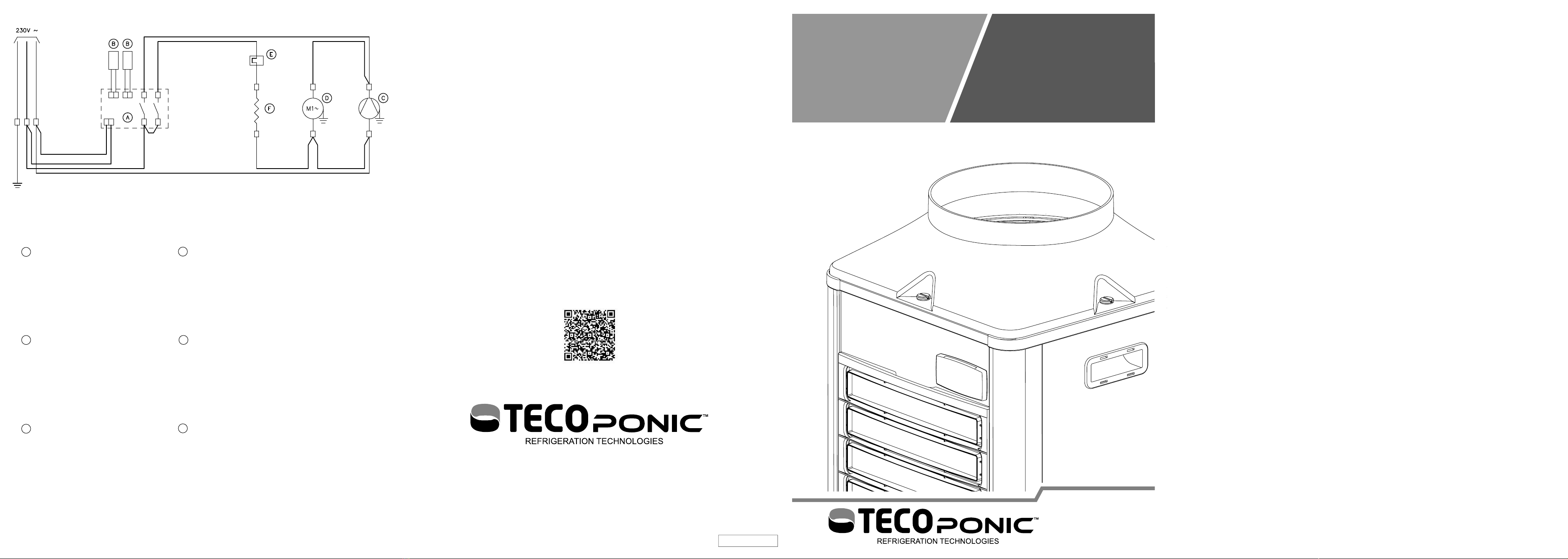
A Termostato
Thermostat
Thermostat
Thermostat
Termostato
Termostato
Termostat
Термостат
温控器
サーモスタット
B Sonda
Probe
Sonde
Sensor
Sonda
Sonda
Sonda
Зонд
探头
ゾンデ
C Compressore
Compressor
Compresseur
Kompressor
Compresor
Compressor
Kompresör
Компрессор
压缩机
コンプレッサー
D Ventilatore
Fan
Ventilateur
Lüfter
Ventilador
Ventilador
Vantilatör
Вентилятор
风扇
ファン
E Termostato di sicurezza
Sefety thermostat
Thermostat de sécurité
Sicherheitsthermostat
Termostato de seguridad
Termostato de segurança
Güvenlik termostatı
Предохранительный термостат
温控器保险装置
安全のためのサーモスタット
F Riscaldatore
Heater
Réchauff eur
Heizer
Calentador
Aquecedor
Isıtıcı
Нагреватель
加热器
ヒーター

12
34
A3
A4
56
E
F
L
N
D
I
M
R
Q
P
78
910
11 12
13 14
A5
A6

1
HYDROPONIC
CHILLER LINE
IT
ATTENZIONE: questo prodotto non è adatto a bambini di età inferiore a
otto anni.
I bambini devono essere controllati per assicurarsi che non giochino con
l’apparecchio.
Questo apparecchio non è destinato ad essere utilizzato da persone (inclu-
si bambini) con ridotte capacità fi siche, sensoriali o mentali, o mancanza di
esperienza e conoscenza, a meno che non sia fornita supervisione o istruzio-
ni sull’uso dell’apparecchio da una persona responsabile della loro sicurez-
za. Pulizia e manutenzione non devono essere fatte da bambini senza sorve-
glianza.
1 MANUALE ISTRUZIONI
1.1 PREMESSA
1.1.1 Avvertenze importanti
Tutti i diritti di riproduzione del presente manuale sono riservati alla TECO S.r.l..
Il presente manuale non può essere ceduto in visione a terzi senza autorizzazione
scritta della TECO S.r.l..
Il testo non può essere usato in altri stampati senza autorizzazione scritta della
TECO S.r.l..
Le descrizioni e le illustrazioni contenute nella presente pubblicazione non sono
impegnative, ferme restando le caratteristiche essenziali del tipo di refrigeratore o
climatizzatore descritto.
La ditta si riserva di apportare le eventuali modifi che che riterrà convenienti per un
miglioramento del prodotto, per esigenze di carattere costruttivo o commerciale, in
qualunque momento e senza impegnarsi ad aggiornare tempestivamente questa
pubblicazione.
La versione aggiornata del presente manuale è disponibile all’indirizzo “www.teco-
online.eu/resources”.
IL PRESENTE MANUALE È PROPRIETÀ DELLA TECO S.r.l. OGNI RIPRODU-
ZIONE ANCHE PARZIALE È VIETATA. © TECO S.r.l.
NOTA: conservare queste istruzioni per riferimenti futuri.
• Non inserire dita o corpi estranei all’interno delle griglie dell’aria. Questo può
causare infortuni dovuti alla rotazione delle pale.
• Non graffi are o tirare il cavo di alimentazione.
• Se si avverte un’anomalia (odore di bruciato, ecc.) disconnettere l’alimentazione
e contattare il rivenditore. Se l’unità continua ad operare in regime di anomalia si
può incorrere nel rischio di incendio, rotture, ecc..
• Se il cavo di alimentazione è danneggiato, deve essere sostituito dal costruttore,
dal rivenditore o da personale tecnico qualifi cato al fi ne di evitare pericoli.
6.1.179.0.02 Ed. 03/2019 TKC HY
2
HYDROPONIC
CHILLER LINE
• Le riparazioni non devono essere eff ettuate dall’utente ma solo da personale tec-
nico. Se queste non vengono eseguite correttamente si può incorrere nel rischio
di incendio o di shock elettrico.
• Scollegare l’alimentazione prima di eff ettuare qualsiasi intervento di manutenzio-
ne all’impianto idroponico.
• Non esporre l’apparecchio agli agenti atmosferici o a fonti di calore dirette. L’ap-
parecchio può essere utilizzato in un intervallo di temperatura ambiente tra i 10°C
e i 38°C (50°F – 100°F). Assicurarsi che le caratteristiche dell’alimentazione
elettrica corrispondano a quelle riportate sulla targhetta “dati tecnici” applicata
sull’apparecchio (vedi paragrafo relativo).
ATTENZIONE: si rammenta che interventi di modifi ca eff ettuati dall’uti-
lizzatore, senza esplicita autorizzazione scritta della TECO S.r.l., fanno
decadere la garanzia e sollevano la TECO S.r.l. da qualsiasi responsa-
bilità per danni causati da prodotto difettoso. Le stesse considerazioni
valgono nel caso si utilizzino pezzi di ricambio non originali o diversi da
quelli esplicitamente indicati da TECO S.r.l..
ATTENZIONE: Mantenere libere da ostruzioni le aperture di ventilazione
nell’involucro dell’apparecchio o nella struttura a incasso.
ATTENZIONE: Non danneggiare il circuito refrigerante.
ATTENZIONE: L’apparecchio può contenere gas R290 infi ammabile (vedi
targhetta Rif. A3 Fig.4). Qualsiasi lavoro di assistenza dovrà essere eff et-
tuato esclusivamente da personale esperto e preparato sulle procedure
di gestione del gas R290.
ATTENZIONE: prima di scollegare l’apparecchio dalle tubazioni è neces-
sario stringere i tubi con le apposite pinze (Rif. B5 Fig. 9) per evitare la
fuoriuscita dell’acqua, una volta riallacciato l’apparecchio riaprire le ap-
posite pinze (Rif. P6 Fig. 9).
L’operatore deve poter essere in grado di verifi care da tutte le posizioni
cui ha accesso che la spina resti disconnessa.
1.2 GARANZIA
Gli apparecchi costruiti dalla TECO S.r.l. sono coperti da GARANZIA, da parte del
rivenditore autorizzato presso cui è stato eff ettuato l’acquisto, come previsto nelle
disposizioni legislative del paese in cui sono commercializzati. Se durante il periodo
di validità, si verifi cassero funzionamenti difettosi o guasti di parti dell’apparecchio,
che rientrano nei casi indicati nella garanzia, il rivenditore autorizzato dopo le oppor-
tune verifi che sull’apparecchio, provvederà alla riparazione o sostituzione delle parti
difettose. Per ottenere il riconoscimento della garanzia è necessario presentare la
documentazione prevista dalle disposizioni legislative del paese in cui è commer-
cializzato l’apparecchio, e alle condizioni previste dal proprio rivenditore o dal centro
assistenza autorizzato TECO.
IT
3
HYDROPONIC
CHILLER LINE
IT
1.3 DESCRIZIONE DEL PRODOTTO
L’apparecchio è idoneo per la climatizzazione dell’acqua negli impianti idro-
ponici. È compatibile con la vita di piante ed elementi organici.
Il prodotto non deve essere utilizzato per scopi diversi da quelli previsti e
sopra specifi cati. Un utilizzo diverso da quello per cui l’apparecchio è stata
realizzato può causare condizioni di pericolo.
1.3.1 Contenuto della confezione
All’apertura della scatola di cartone controllare la presenza di tutti gli accessori (Fig. 5):
D Viti in plastica ¼ di giro per fi ssaggio convogliatore 4
E Convogliatore 1
F Manuale istruzioni 1
I Fascette per bloccaggio tubi 4
L Chiave fi ssaggio convogliatore aria 1
M Raccordi di collegamento tubi completi di guarnizioni 2
N Pinze schiaccia tubo 2
R Riduzioni tubo 2
Verifi care attraverso la targhetta dei dati tecnici (Rif. A3 Fig. 4) che l’apparecchio
contenuto nell’imballo corrisponda al modello acquistato.
1.4 ORGANIZZAZIONE MANUALE/MODALITÀ DI CONSULTAZIONE
1.4.1 STRUTTURA DEL MANUALE
Il manuale è diviso in capitoli, che radunano per argomenti tutte le informazioni ne-
cessarie per utilizzare il prodotto senza alcun rischio.
1.4.2 DESCRIZIONE DEI PITTOGRAMMI
Sul manuale verranno utilizzati i seguenti simboli per evidenziare indicazioni ed av-
vertenze particolarmente importanti:
ATTENZIONE: Questo simbolo indica norme antinfortunistiche per l’ope-
ratore e/o per eventuali persone esposte.
AVVERTENZA: Questo simbolo indica che esiste la possibilità di arreca-
re danno al prodotto e/o ai suoi componenti.
NOTA: Questo simbolo segnala informazioni utili.
1.5 INSTALLAZIONE E FUNZIONAMENTO
1.5.1 DISIMBALLO DELL’APPARECCHIO
AVVERTENZA: non capovolgere l’imballo o l’apparecchio. Conservare
l’imballo integro per movimentazioni future.
1) Aprire l’imballo e togliere gli accessori (Fig.2).
2) Sfi lare il contenuto, senza ribaltarlo, prendendolo dalle maniglie laterali (Rif.B
Fig.3).
3) Togliere il polistirolo (Rif. C Fig. 3).
4) Togliere il sacchetto di plastica.

4
HYDROPONIC
CHILLER LINE
IT
1.5.2 INSTALLAZIONE E FUZIONAMENTO DELL’APPARECCHIO
1) Non installare o cercare di riparare l’apparecchio se questo ha subito danni
durante il trasporto.
2) Non connettere il cavo di alimentazione alla presa elettrica se non quando spe-
cifi catamente richiesto.
3) Per garantire il corretto funzionamento dell’apparecchio in condizioni di sicu-
rezza, è assolutamente vietato esporlo agli agenti atmosferici e a fonti di calore
dirette (Fig. 1). La temperatura nell’ambiente di installazione deve essere com-
presa tra i 10 °C e i 38 °C (50 °F – 100 °F).
4) Inserire le viti in plastica (Rif. D Fig. 5) nei fori quadrati del convogliatore (Rif. E
Fig. 5).
5)
Montare il convogliatore (Rif. E Fig. 5) e fi ssarlo ruotando le viti di un quarto di
giro in senso antiorario (Rif. Q Fig. 6) per mezzo della chiave in dotazione (Rif.
P Fig.6).
6) Distanze minime dalle pareti e caratteristiche del tubo (non fornito) se si vuole
convogliare l’aria.
AVVERTENZA: Non inserire fi ltri nel tubo o altri elementi che ostacoli-
no il fl usso d’aria.
7) L’apparecchio deve essere installato in un ambiente areato o in associazione
a una grow box. Se l’installazione è all’esterno (Fig.11) o all’interno della grow
box (Fig.12), è possibile connettere al convogliatore un tubo (non fornito) (vedi
Tab. 5-2) per l’evacuazione dell’aria calda.
8) Predisporre i tubi dell’acqua come segue:
8.1) Se necessario, infi lare prima la pinza schiaccia tubo (Rif. P2 Fig. 8) quindi la
fascetta blocca tubo (Rif. P3 Fig. 8).
8.2) Infi lare il raccordo (Rif. P4 Fig. 8) nel tubo, e portare la fascetta blocca tubo sul
raccordo (Rif. P5 Fig. 8).
8.3)
Avvitare in senso orario il raccordo (Rif. P7 Fig. 10 orientandolo secondo le proprie
necessità e stringere a fondo.
8.4) Nel collegare i tubi, verifi care che il tubo proveniente dalla pompa (non fornita)
e/o dal gruppo fi ltro (non forniti con l’apparecchio) sia collegato nella posizione
indicata con IN (Rif. P8 Fig. 10) e che il tubo di ritorno sia collegato nella posi-
zione indicata con OUT (Rif. P9 Fig. 10).
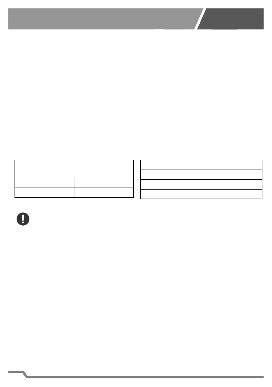
Distanze minime dalle pareti
Lato ingresso aria 50 mm – 1,97 in
Lato uscita aria 50 mm – 1,97 in
Tab. 1-1
Caratteristiche del tubo
Diametro interno tubo 200mm (7,87in)
Lunghezza massima del tubo 2m (78in)
Massimo una curva a 90°
Tab. 1-2

5
HYDROPONIC
CHILLER LINE
IT
9) Sistemare l’apparecchio nel luogo scelto consentendo la visibilità dello stru-
mento. Rispettare le distanze minime dalle pareti (Tab. 5-1).
10) Mettere in funzione la pompa, se necessario riaprire le pinze schiaccia tubo
(Rif. P6 Fig. 9), assicurarsi che l’acqua circoli regolarmente all’interno del circu-
ito e che non vi siano perdite. In caso di anomalie del circuito idraulico o perdite
dello stesso, rivedere le connessioni.
11) AVVERTENZA: assicurarsi che l’acqua che arriva all’apparecchio sia
fi ltrata.
12) Assicurarsi che le caratteristiche dell’alimentazione elettrica corrispondano a
quelle riportate sulla targhetta dei dati tecnici applicata sul retro dell’apparec-
chio (Rif. A3 Fig. 4).
13) Con la pompa in funzione, inserire il cavo di alimentazione nella presa di cor-
rente, sul display comparirà la scritta OFF. Premendo il pulsante di accensione
(Rif. A7 Fig. 14) per almeno 3 secondi, il vostro apparecchio entrerà in funzione,
sul display è indicata la temperatura dell’acqua. Per visualizzare la temperatura
da raggiungere premere il tasto SET (Rif. A8 Fig. 14), per tornare alla tempera-
tura dell’acqua premere nuovamente il tasto SET (Rif. A8 Fig. 14) o attendere 5
secondi.
14) AVVERTENZA: per evitare guasti al compressore è stato previsto un
ritardo di 2 minuti al primo avviamento.
15) Per fermare l’apparecchio premere il pulsante di accensione (Rif. A7 Fig. 14)
per almeno 3 secondi, sul display comparirà la scritta OFF.
AVVERTENZA: L’apparecchio deve essere installato ad un’altezza infe-
riore al livello dell’acqua.
AVVERTENZA: Per evitare danni l’apparecchio non può funzionare sen-
za la circolazione dell’acqua (pompa spenta).
AVVERTENZA: Nel connettore (Rif. A4 Fig. 4) collegare esclusivamente il
modulo TECOnnect Wi-Fi (non fornito). Non collegare a questo connet-
tore nessun altro dispositivo per non danneggiare il termostato dell’ap-
parecchio.
6
HYDROPONIC
CHILLER LINE
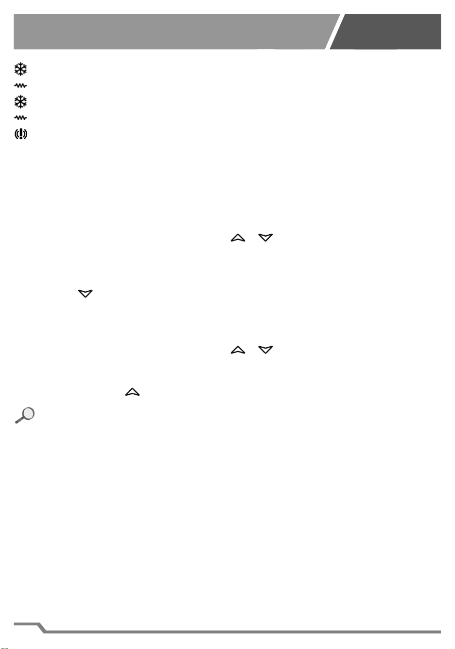
1.5.3 Indicazioni presenti sul display
Acceso: apparecchio in funzione raff reddamento (Rif. A9 Fig. 14).
Acceso: apparecchio in funzione riscaldamento (Rif. B1 Fig. 14).
Lampeggiante: apparecchio pronto per il raff reddamento (Rif. A9 Fig. 14).
Lampeggiante: apparecchio pronto per il riscaldamento (Rif. B1 Fig. 14).
Acceso: condizione di allarme (Rif. A1 Fig. 14).
1.5.4 Regolazioni termostato
Fare riferimento alla fi gura 14 per l’individuazione dei pulsanti.
1) Per modifi care la temperatura dell’acqua:
a. Premere per 3 secondi il tasto SET (Rif. A8), viene visualizzato il valore attual-
mente impostato e l’icona dell’unità di misura (C o F Rif. C3) inizia a lampeg-
giare.
b. Modifi care il valore utilizzando i tasti e (Rif. C2 e A7).
c. Premere il tasto SET (Rif. A8) per confermare il valore impostato.
2) Per regolare il parametro esclusione della resistenza (o1).
d. Accedere al menu di programmazione tenendo premuti per 3 secondi i tasti
SET + (Rif. A8 e A7). L’icona dell’unità di misura selezionata inizia a lam-
peggiare (C o F Rif. C3) e appare o1
e. Premere il tasto SET (Rif. A8), viene visualizzato il valore attualmente imposta-
to.
f. Modifi care il valore utilizzando i tasti e (Rif. C2 e A7).
g. Premere il tasto SET (Rif. A8) per confermare il valore impostato e passare al
parametro successivo.
h. Premere SET + (Rif. A8 e C2) per uscire dalla programmazione.
NOTA: se non si preme nessun tasto per 30 secondi, tutti i valori impo-
stati vengono memorizzati e l’apparecchio si predispone per il funziona-
mento.
IT

7
HYDROPONIC
CHILLER LINE
Para-
metro
Valore
Preimpostato
Descrizione Intervallo di
regolazione
o1 On
Attivazione / disattivazione funzione di riscal-
damento: impostare su “On” per attivare la
resistenza, impostare su “OFF” per disattiva-
re la resistenza.
On - OFF
rL xx.x Versione fi rmware termostato.
Parametro in sola lettura. -
Tab. 1-3
1.6 TRASPORTO ED IMMAGAZZINAMENTO
L’apparecchio deve essere movimentato delicatamente in posizione verticale utiliz-
zando le apposite maniglie. Va posizionato su una superfi cie piana.
1.7 DEMOLIZIONE E SMALTIMENTO
L’etichetta con il cassonetto barrato presente sul prodotto indica che il pro-
dotto non deve essere smaltito tramite la procedura normale di smaltimento
dei rifi uti domestici. Per evitare eventuali danni all’ambiente e alla salute
umana, separare questo prodotto da altri rifi uti domestici in modo che possa
venire riciclato in base alle procedure di rispetto ambientale. Per maggiori dettagli
sui centri di raccolta disponibili, contattare l’uffi cio governativo locale o il rivenditore
del prodotto.
Queste informazioni si applicano solo ai clienti dell’Unione europea, conformemen-
te alla direttiva 2002/96/CE del Parlamento europeo e del Consiglio del 27 Gennaio
del 2003, sui rifi uti di apparecchiature elettriche ed elettroniche (RAEE) e le norme
che ne sanciscono il recepimento e l’attuazione nei vari sistemi giuridici nazionali.
Per altri paesi, contattare il governo locale per studiare la possibilità di riciclare il
vostro prodotto.
IT
8
HYDROPONIC
CHILLER LINE
1.8 DIAGNOSTICA, INCONVENIENTI, CAUSE E RIMEDI
1.8.1 MANUTENZIONE ORDINARIA
La pulizia del fi ltro va eseguita con la frequenza di almeno una volta al mese e co-
munque secondo il grado di polverosità dell’ambiente d’installazione.
Aprire la griglia di plastica (Rif. A6 Fig. 13) dalla parte superiore e sfi lare il fi ltro (Rif.
A5 Fig. 13).
Pulire il fi ltro lavandolo con acqua tiepida.
AVVERTENZA: Non utilizzare spazzole dure o materiali contundenti per
evitare danneggiamenti al fi ltro.
Riposizionare il fi ltro (Rif. A5 Fig. 13) e chiudere la griglia di plastica (Rif. A6 Fig. 13).
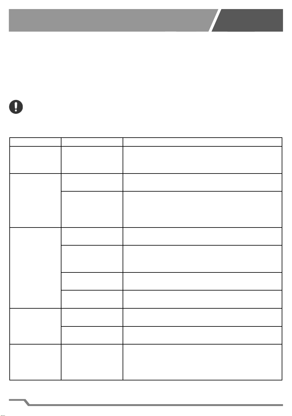
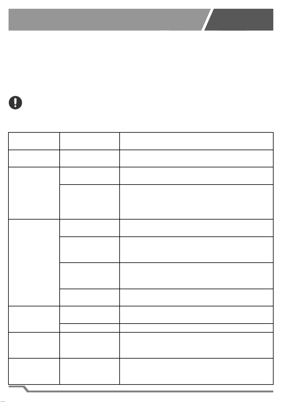
2 TABELLA INCONVENIENTI, CAUSE E RIMEDI
Inconvenienti
Cause Rimedi
Il display non
si accende.
Mancanza di ali-
mentazione elet-
trica.
Controllare che la spina sia inserita a fondo nel-
la presa di corrente.
Scarso raf-
freddamento
dell’acqua.
Flusso acqua in-
suffi ciente.
Controllare il corretto funzionamento della pom-
pa (non fornita).
Aria in uscita dal-
la griglia di venti-
lazione a tempe-
ratura ambiente.
Mancanza gas nel compressore, rivolgersi al
rivenditore TECO S.r.l. di zona.
Filtro aria sporco. Pulire il fi ltro come indicato nel capitolo 6 Ma-
nutenzione.
Sul display
compare il
messaggio
“HA2”, (surri-
scaldamento).
Temperatura am-
biente troppo ele-
vata.
Ripristinare le condizioni ambientali ottimali. La
temperatura ambiente massima consentita è
di 38 °C (100 °F).
Bocchette di ven-
tilazione ostruite.
Liberare le bocchette o collocare il climatizzato-
re in ambiente idoneo.
Sistema di venti-
lazione guasto. Rivolgersi al rivenditore TECO S.r.l. di zona.
Scarso ri-
scaldamento
dell’acqua.
Flusso acqua in-
suffi ciente.
Controllare il corretto funzionamento della pom-
pa (non fornita).
Resistenza gua-
sta. Rivolgersi al rivenditore TECO S.r.l. di zona.
Sul display
compare il
messaggio
“P1”.
Guasto della son-
da di temperatura
acqua.
Rivolgersi al rivenditore TECO S.r.l. di zona.
IT
9
HYDROPONIC
CHILLER LINE
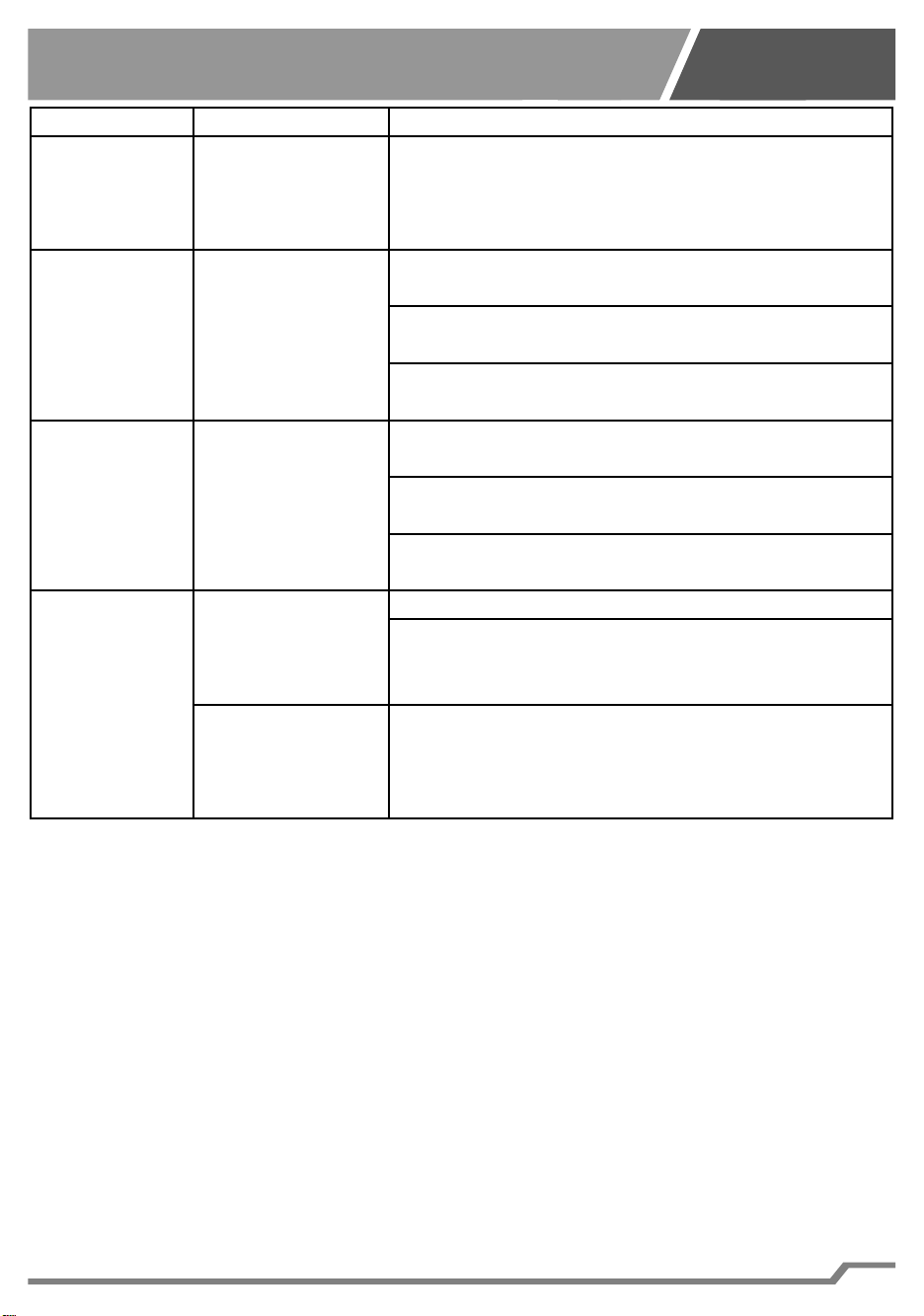
Inconvenienti
Cause Rimedi
Sul display
compare il
messaggio
“P2”.
Guasto della son-
da di surriscalda-
mento
Rivolgersi al rivenditore TECO S.r.l. di zona.
Sul display
compare il
messaggio
“HA”.
Alta temperatura
dell’acqua.
Controllare il corretto funzionamento della pom-
pa (non fornita).
Verifi care che non ci siano strozzature delle tu-
bazioni.
Verifi care che la funzione di raff reddamento sia
attiva.
Sul display
compare il
messaggio
“LA”.
Bassa tempera-
tura dell’acqua.
Controllare il corretto funzionamento della pom-
pa (non fornita).
Verifi care che non ci siano strozzature delle tu-
bazioni.
Verifi care che la funzione di riscaldamento sia
attiva (ove presente).
La temperatu-
ra visualizza-
ta sul display
dell’apparec-
chio non cor-
risponde a
quella eff etti-
va.
L’acqua non cir-
cola correttamen-
te all’interno del
circuito idraulico.
Verifi care eventuali strozzature delle tubazioni.
Verifi care l’effi cienza della pompa (non fornita).
Tubazioni lunghe
e non isolate.
Accorciare il più possibile le tubazioni e isolarle
termicamente.
Tab. 2-1
IT
10
HYDROPONIC
CHILLER LINE
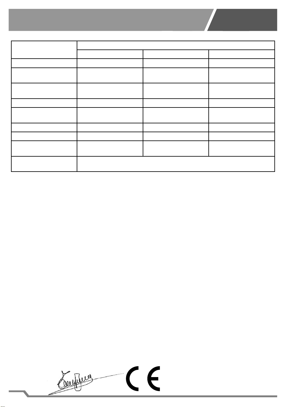
3 DATI E CARATTERISTICHE TECNICHE
Specifi che Modello
HY 500 / HY 500 H HY 1000 / HY 1000 H HY 2000 / HY 2000 H
Alimentazione 230V - 50Hz 230V - 50Hz 230V - 50Hz
Potenza elettrica assor-
bita (raff reddamento)*
280 W (R134a)
260 W (R290)
370 W (R134a)
300 W (R290)
590 W (R134a)
400 W (R290)
Potenza elettrica assor-
bita (riscaldamento)
- W - HY500
400 W - HY500H
- W - HY1000
400 W - HY1000H
- W - HY2000
400 W - HY2000H
Entrata/uscita acqua 16 mm - 3/4 in 16 mm - 3/4 in 16 mm - 3/4 in
Flusso acqua minimo /
massimo
400 l/h – 106 gal/h
800 l/h – 211 gal/h
500 l/h - 132 gal/h
800 l/h – 211 gal/h
600 l/h – 159 gal/h
800 l/h – 211 gal/h
Pressione massima 1 bar / 14,4 PSI 1 bar / 14,4 PSI 1 bar / 14,4 PSI
Peso 16,5 kg - 36,4 lb 19,7 kg - 43,4 lb 21,4 kg - 47,2 lb
Dimensioni 310 x 310 x 440 (h) mm
12,2 x 12,2 x 17,3 (h) in
310 x 310 x 482 (h) mm
12,2 x 12,2 x 19 (h) in
310 x 310 x 524 (h) mm
12,2 x 12,2 x 20,6 (h) in
Gas presente all’interno
del l’apparecchio
Verifi care quale gas è presente nel modello acquistato vedi targhetta Rif. A3
Fig.4
*Temperatura dell’acqua 20°C (68°F) - Tutti i dati sono indicativi e possono essere variati senza preavviso da TECO.
Tab. 3-1
L’apparecchio può contenere gas fl uorurati ad eff etto serra disciplinati dal protocollo di Kyoto.
Vedi targhetta Rif. A3 Fig.4. Tipo di gas R134a valore GWP:1430
4 DICHIARAZIONE CE DI CONFORMITÀ
LA SOTTOSCRITTA
TECO S.r.l. - TECNOLOGIE DI REFRIGERAZIONE
Sede Legale, Amministrativa e Commerciale:
Via G. Ricci Curbastro, 8 - 48124 Fornace Zarattini, RAVENNA - C. F. / P. IVA 01075610392
DICHIARA SOTTO LA PROPRIA RESPONSABILITÀ CHE IL PRODOTTO NUOVO
MOD.: HY500, HY500H, HY1000, HY1000H, HY2000, HY2000H
AL QUALE QUESTA DICHIARAZIONE SI RIFERISCE È CONFORME ALLE SEGUENTI DISPOSI-
ZIONI:
DIRETTIVA COMPATIBILITÀ ELETTROMAGNETICA 2014/30/EU
DIRETTIVA SICUREZZA BASSA TENSIONE 2014/35/EU
È STATO REALIZZATO SECONDO LE SEGUENTI NORME ARMONIZZATE:
Sicurezza
Codice della Norma utilizzata:
EN 60335 - 1 / EN 60335 - 2 - 55 / EN 60335 - 2 - 24 E SUCCESSIVE MODIFICHE
Compatibilità Elettromagnetica
Codice della Norma utilizzata:
EN 55014-1 / EN 55014-2 / EN 61000-3-2 / EN 61000-3-3 / EN 61000-6-1 / EN 61000-6-3 E SUC-
CESSIVE MODIFICHE
La persona autorizzata a costituire la documentazione tecnica è:
Nome: Turci Bruno Via G. Ricci Curbastro, 8 - 48124 Fornace Zarattini, RAVENNA
Turci Bruno Ravenna 01/10/2018
Manager
r
un
o
e
r
IT

11
HYDROPONIC
CHILLER LINE
EN
WARNING: This product is not suitable for children under eight years.
It is essential to ensure that children do not play with the device.
This device is not intended for use by persons (including children) with lim-
ited physical, sensorial or mental abilities, or lacking in experience and know-
how, unless supervision or instructions for using the device are provided by
the person responsible for their safety.
Cleaning and maintenance shall not be made by children without supervision.
1 INSTRUCTIONS MANUAL
1.1 INTRODUCTION
1.1.1 Important Notes
All rights of reproduction of this manual are reserved by TECO Srl. This manual
cannot be inspected by a third-party without prior written authorization of TECO Srl
The text of this manual cannot be used in other printed matter without written au-
thorization of TECO Srl.
Descriptions and illustrations in this publication are not binding, while the chiller and
air conditioner ‘s essential characteristics remain the same.
The manufacturer reserves the right to make any modifi cations considered appro-
priate to improve the product or for requirements of a constructional or commercial
nature, at any time and without undertaking to update this publication immediately.
Please visit the website “www.tecoonline.eu/resources” for updated version of this
manual.
THIS MANUAL IS PROPERTY OF TECO S.r.l. ANY REPRODUCTION, EVEN
PARTIAL, IS PROHIBITED. ©TECO S.r.l.
NOTE: Please keep these instructions for future references.
1.1.2 Important Notes
• To avoid the possibility of personal injury from the rotating blades, never insert
your fi ngers or any foreign bodies into the air outlet grille.
• Do not scratch or pull the power supply cord.
• If you detect any anomalies (such as a burning smell etc.) disconnect the power
plug and contact your dealer. Fire or breakage may occur if you continue to oper-
ate the unit under abnormal situation.
• If the power supply cord is damaged it must be replaced by the manufacturer, the
dealer or a qualifi ed technician in order to avoid any hazard.
• Repair may be carried out only by qualifi ed persons. If this are not performed
properly, they can cause electric shocks, burns and fi res.
• Unplug power supply before performing any maintenance work on the hydro-
ponic system.
• Do not expose the device to atmospheric agents or to direct heat sources. The

12
HYDROPONIC
CHILLER LINE
EN
device can be used within an ambient temperature range of 10°C and 38°C (50°F
- 100°F). Make sure that the power supply requirements correspond to those indi-
cated on the label “technical data” affi xed to the device (see related paragraph).
WARNING: Unauthorized modifi cations or repairs carried out by the user
without written authorization by TECO Srl will void the warranty and dis-
charge TECO Srl from liability for damages caused by defective prod-
ucts. The same considerations are valid if you use non-original spare
parts or other than those explicitly specifi ed by TECO Srl.
WARNING: Keep ventilation openings, in the appliance enclosure or in
the built-in structure, clear of obstruction.
WARNING: Do not damage the refrigerant circuit.
WARNING: The appliance can contain fl ammable R290 gas (see plate Rif.
A3 Fig. 4).
Any assistance work must be carried out exclusively by experienced and
prepared personnel observing recognised R290 gas management proce-
dures.
WARNING: Before you unplug the device from the pipes it is necessary
to tighten the pipes with the special squeeze-tube clamp (Ref. B5 Fig. 9)
to prevent the escape of water, once reconnected the unit to re-open the
clamp.
Make sure that the operator can check from any point he has access that the
plug remains disconnected.
Close also the pipes to prevent water leakage.
1.2 WARRANTY
The appliance evices manufactured by TECO S.r.l. are covered by warranty by the
dealer through them the product was purchased from, as provided for in the laws of
the country in which they are sold. If an equipment malfunction or failure, listed in
the warranty conditions, occurs during the validity period; after checking the unit,
the authorized dealer will repair or replace defective parts. In order to obtain the
recognition of the warranty it is necessary to submit documentation required under
the law of the country where the device is sold and under the dealer’s conditions or
conditions provided by the authorized service center TECO.
13
HYDROPONIC
CHILLER LINE
1.3 DESCRIPTION OF THE PRODUCT
This appliance is suitable for water conditioning in hydroponic systems.
It is compatible with life of plants and organic compounds.
The appliance should not be used for purposes other than those provided for
and specifi ed above. Any other use than that for which the product was made
may cause hazardous conditions.
1.3.1 Package Contents
Open the box and verify that the following accessories are present (Fig. 5):
D ¼ turn plastic screws for conveyor fastening 4
E Conveyor 1
F Instruction Manual 1
I Cable-tie-wrap 4
L Key fi xing air conveyor 1
M Pipe connection fi ttings (including gaskets) 2
N Squeeze-tube clamp 2
R Tube reductions 2
Check the technical plate of the unit (Ref. A3 Fig. 4) to make sure that the device
contained in the package matches the model you purchased.
1.4 MANUAL ORGANIZATION AND CONSULTATION MODE
1.4.1 MANUAL STRUCTURE
The manual is divided into chapters, each corresponding to main topics, that provide
information required to use the product without any risk.
1.4.2 DESCRIPTION OF PICTOGRAPHS
In this manual the following symbols are used to highlight specifi c information and
warnings:
WARNING: This symbol indicates safety regulations for the operator and/
or for people who may be exposed.
CAUTION: This symbol indicates that there is a possibility of damage to
the product and/or its components.
NOTES: This symbol indicates useful information
1.5 INSTALLATION AND OPERATION
1.5.1 UNPACKING OF THE DEVICE
CAUTION: do not turn upside down neither the packaging nor the ap-
pliance. Keep the packaging box and materials for future movement or
transport.
1) Open the packaging and remove the accessories (Fig. 2).
2) Pull out the device grasping side handles, without overturning it (Rif. B Fig. 3).
3) Remove the polystyrene (Rif. C Fig. 3).
4) Remove the plastic bag.
EN
14
HYDROPONIC
CHILLER LINE
1.5.2 INSTALLATION AND FUNCTIONING OF THE APPLIANCE
1) Do not install and do not try to repair the appliance if it was damaged during
transport.
2) Do not connect the power cord to the power supply, unless specifi cally required.
3) In order to ensure the correct working of the device in safe conditions, it is ab-
solutely forbidden to expose the appliance to atmospheric agents and to direct
heat sources (Fig. 1). The temperature of the installation environment has to be
between 10 °C and 38 °C (50 °F – 100 °F).
4) Insert the plastic screws (Ref. D Fig.5) in the square holes of the conveyor (Ref.
E Fig.5).
5) Assemble the conveyor (Ref. E Fig.5) and fasten it turning the screws a quarter
of a rotation anti-clockwise (Ref. Q Fig.6) using the wrench supplied (Ref. P
Fig.6).
6) Minimum distances from the walls and characteristics of the tube (not supplied)
if you want to convey air.
CAUTION: Do not insert the fi lters in the tube or other elements which
could obstruct the air fl ow.
7) The appliance must be installed in a ventilated environment or combined with
a grow box. If installation is outside (Fig.11) or inside the grow box (Fig.12), a
tube (not supplied) can be connected to the conveyor (see Tab. 5-2) for hot air
evacuation.
8) Prepare the water tubes as follows:
8.1) If necessary, insert before the squeeze-tube clamp (Ref. P2 Fig.9) then the
cable-tie-wrap (Ref. P3 Fig. 8).
8.2) Insert the joint ( Ref. P4 Fig. 8) in the tube, and bring cable-tie-wrap on the joint
( Ref. P5 Fig. 8).
8.3) Fasten the joint clockwise (Ref. P7 Fig. 10), direct it as needed and tighten it .
8.4) When connecting the pipes, make sure that the pipe from the pump (not sup-
plied) and/or the fi lter assembly (not supplied with the unit) is connected in the
position indicated with IN (Ref. P8 Fig. 10), and that the return pipe is connected
to the hydroponic system in the position indicated with OUT (Ref. P9 Fig. 10).
9) Install the appliance in the chosen place allowing the visibility of the equipment.
10) Start the pump, if necessary reopen the squeeze-tube clamp (Ref. P6 Fig. 9)
Minimum distance from the walls
(Fig.7)
Air input side 50 mm – 1,97 in
Air output side 50 mm – 1,97 in
Tab. 1-1
Characteristics of the tube
Tube inner diameter 200mm (7.87in)
Maximum length of tube 2m (78in)
Maximum one 90° curve
Tab. 1-2
EN

15
HYDROPONIC
CHILLER LINE
EN
, make sure that the water fl ows regularly in the circuit and that there are no
leaks. In the case of anomalies or leakage in the hydraulic circuit, review the
connections.
11) CAUTION: Make sure that the water that reaches the device is fi ltered.
12) Make sure that the power supply requirements match those shown on the tech-
nical plate, visible on the back of the unit (Ref. A3 Fig. 4).
13) When the aquarium pump is functioning, connect the cable power supply to the
power socket with the plug. Then, the display will show OFF.
Pressing the power button (Ref. A7 Fig. 14) for at least 3 seconds, your device
will start working, on the display it is indicated the actual water temperature. To
display the temperature to be reached press the SET button (Ref.A8 Fig.14) to
return to the water temperature press the SET button (Ref.A8 Fig.14) or wait for
5 seconds.
14) CAUTION: A 2-minutes delay was added to prevent compressor failure
at the fi rst start.
15) To stop the device, press the power button (Ref. A7 Fig. 14) for at least 3 sec-
onds, the display will show OFF.
CAUTION: The appliance must be installed at a height below the water
level.
CAUTION: To prevent damages, the unit cannot operate without water
fl ow (pump off ).
CAUTION: Connect only the TECOnnect Wi-Fi module (not supplied) to
connector (Ref. A4 Fig. 4). Do not connect any other device to this con-
nector in order not to damage the chiller thermostat.

16
HYDROPONIC
CHILLER LINE
EN
1.5.3 Information on the display
On: unit in cooling mode (Ref. A9 Fig. 14).
On: unit in heating mode (Rif. B1 Fig. 14).
Flashing light: unit ready for cooling (Rif. A9 Fig. 14).
Flashing light: unit ready for heating (Rif. B1 Fig. 14).
On: alarm condition (Rif. A1 Fig. 14).
1.5.4 Thermostat settings
Refer to fi gure 14 for buttons detection.
1) To change the temperature of the water:
a. Push the button SET for 3 seconds (Rif. A8), display shows the current value
setting and the unit of measure icon (C or F ref C3) starts to blinking.
b. Modify the parameters using the arrows and (Rif. C2 and A7)
c. Push the button SET (Rif. A8) to confi rm the values.
2) To adjust the parameter heater (o1)
d. Access to the programming menu by pressing the SET+ button for 3 sec-
onds (Ref. A7 and A8). The icon of the unit of measure selected starts blinking
(C or F Ref. C3) and o1 appears.
e. Press the SET button (ref A8), the current set value is displayed.
f. Change the value using the arrows and (Rif. C2 and A7).
g. Press the SET button (Ref. A8) to confi rm the setting and move to the next
parameter.
h. Press SET + (Ref. A8 and C2) to exit programming mode.
NOTE: If you do not press any buttons for 30 seconds, all settings are
saved and the device is ready for operation.

17
HYDROPONIC
CHILLER LINE
Para-
meter
Preset va-
lue
Description Regulation
range
o1 On
Activation / deactivation of the heating func-
tion:
- Set “On” to activate the heating function
- Set “OFF” to deactivate the heating func-
tion.
On - OFF
rL xx.x Firmware version of thermostat.
Read-only parameter. -
Tab. 1-3
1.6 TRANSPORTATION AND STORAGE
The appliance must be handled carefully in a vertical position using the handles. It
is recommended to placed it on a fl at surface.
1.7 DEMOLITION AND DISPOSAL
The crossed-out wheelie bin label that can be found on your products, indi-
cates that the product may not be treated as household waste. By ensuring
that this product is disposed of correctly, you will help preventing potential
negative consequences for the environment and human health, which could
otherwise be caused by inappropriate waste handling of these products. For more
detailed information about recycling of this product, please contact your local city
offi ce, your household waste disposal or the dealer where you purchased this prod-
uct.
This information only applies to customers in the European Union, according to Di-
rective 2002/96/EC of EUROPEAN PARLIAMENT and THE COUNCIL OF 27Jan-
uary 2003 on waste electrical and electronic equipment (WEEE) and legislation
transposing and implementing it info the various notional legal systems. For other
countries, please contact your local government to investigate the possibility of re-
cycling your product.
EN
18
HYDROPONIC
CHILLER LINE
1.8 MANTAINANCE
1.8.1 ROUTINE MAINTENANCE
Filter cleaning should be carried out at least once every month and whenever it’s
necessary according to the level of dust in the installation place.
Open the plastic grid from the top (Rif. A6 Fig. 13) and remove the fi lter (Rif. A5 Fig.
13).
Clean out the fi lter by washing it with warm water.
CAUTION: Do not use hard brushes or blunt instruments to avoid dam-
aging the fi lter.
Replace the fi lter (Ref. A5 Fig. 13) and close the plastic grid (Ref. A6 Fig. 13).
2 DIAGNOSTICS, PROBLEMS, CAUSES AND REMEDIES
Disadvantag-
es Causes Remedies
Display does
not light up. No electricity Check if the power supply plug is fully inserted
into the power outlet (Rif. A5 Fig. 4).
Insuffi cient wa-
ter cooling.
Insuffi cient water
fl ow.
Check the proper operation of the pump (not
supplied).
Outgoing air from
the ventilation
grid at room tem-
perature.
Lack of gas in the compressor, contact the
TECO S.r.l area retailer.
On the dis-
play appears
the message
“HA2” (over-
heating).
Dirty air fi lter. Clean the air fi lter following the instruction
(Chapter 6 Maintenance).
Ambient temper-
ature is too high.
Restore the optimal environmental conditions.
The maximum ambient temperature allowed is
38°C (100°F).
Obstructed venti-
lation grate.
Remove the obstruction from the ventilation
grate or place the chiller in one most suitable
environment.
Broken ventila-
tion system. Contact the TECO S.r.l area retailer.
Insuffi cient wa-
ter heating.
Insuffi cient water
fl ow.
Check the correct operation of the pump (not
supplied).
Defective heater. Contact the TECO S.r.l area retailer.
On the display
appears the
message “P1”.
Damage of the
water’s tempera-
ture probe.
Contact the TECO S.r.l area retailer.
On the display
appears the
message “P2”.
Damage of the
overheating tem-
perature probe.
Contact the TECO S.r.l area retailer.
EN
This manual suits for next models
5
Table of contents
Languages:
Other TecoPonic Chiller manuals

Popular Chiller manuals by other brands

Trane
Trane RTAA-70 Installation & maintenance guide

Carrier
Carrier Omnizone 50BVC Installation, Start-Up, Service and Controls Operation and Troubleshooting

York
York YGWH 115 Installation, commissioning & operation

Galletti
Galletti PERFORMA MPE Series Technical manual

SMC Networks
SMC Networks HRR Series manual

Daikin
Daikin EWAQ016CAW Installation and operation manual


