Tecprecision TA-605 Specification sheet

TA-605
(1)(2) Line Input/Sub-Input : This allows connection to any head unit that has a RCA outputs.
(3) Input-selector switch : The sub outputs si
g
nal is a sum of the Ch1+2(Front) and ch3+4(Rear) outputs.
All three inputs will accept si
g
nal for use with a head unit with three preamp outputs.
1) When set to "1+2Ch" position, the front Inputs (Ch1+2) will provide si
g
nal for the entire Amplifier.
2) When set to "1+2Ch, 3+4Ch" position, both the front and rear inputs will accept si
g
nal allowin
g
the use of head unit fader.
3) When set to "1+2Ch, 3+4Ch, SUB" all three inputs wil accept si
g
nal seperately for use with a headunit with thre preamp outputs.
(4)(7)(11) LEVEL : This allows level ad
j
ustment of the input si
g
nal. Use this control to correctly match the head unit to 3/4 volume, with the
BASS and TREBLE on zero, then slowly turn up the amplifier level control towards the MAX end of the control, NOTE : If the sound becomes
distorted, turn this control down.
(5)(8)(10) "Hi
g
h-Pass" frequency control : This control is active when the switch is set to "Hi-pass" and permits selection of the
desired crossover frequency.
(5)(8)(10) "Low-Pass" frequency control : This control is active when the switch is set to "Low-pass" and permits selection of the
desired crossover frequency.
(6)(9)(12) CROSSOVER SELECTOR : Set the appropriate mode of operation. The 3 positions available are FLAT, HIGH PASS and LOW PASS.
(13) POWER LED : When illuminated the amplifier is turned on.
(14) PROTECTION LED : When illuminated it indicates a fault has occurred. Check installation.
(15) +12V : This must be connected directly th the vehicle batteries positive(+) terminal via an inline fuse at the battery end.
Note : This is to be the lasst wire to hook up durin
g
installation as dama
g
e could result.
(16) REMOTE : This terminal is for turnin
g
the amplifier on and off. This requires a requires a switched positive (+12V) to power "on" the
amplifier, this can be found on the rear of the head unit in the form of a electric antenna output, or a remote on output. Of not available you
can wire to the ACC position on the key.
(17) GROUND : Connect directly to the vehicle's chassis.
NOTE : This is to be the first wire to hook up durin
g
installation as dama
g
e could result.
(18) FUSE : Please ensure correct type of fuse is fitted, as specified in this manual.
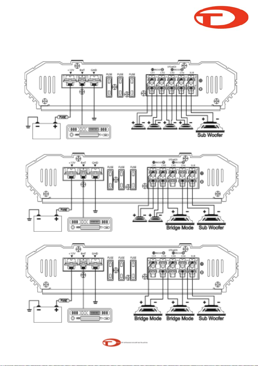
(19) Loudspeaker connections : (If the amplifier is to be connected in a brid
g
ed mode, proceed with the section "Brid
g
ed loudspeaker
connections".) As with any audio component, connection of the amplifier and speakers with the correct polarity is essential for
g
oods bass
reproduction. Ensure there fore when connection that the positive (+) loudspeaker terminal.
The same applies to the ne
g
ative (-) terminals. The left-hand amplifier channel must also be connected to the left-hand loudspeaker and the
ri
g
ht-hand the ri
g
ht-hand amplifier channel to the ri
g
ht-hand loudspeaker.
B
r
idg
e
d l
ou
d
spea
k
er
connec
ti
ons
:
Th
e
AMP
can
a
l
so
b
e
b
r
idg
e
i
n
a
mono
con
fig
ura
ti
on.
Thi
s
ena
bl
es
you
t
o
use the amplifier for one or more subwoofer(s) or amid-ran
g
e speaker. In this confi
g
uration the amplifier sums the ri
g
ht-hand and oeft-hand channel
deliverin
g
a sin
g
le channel (mono) output.
Note : The amplifier can sum the ri
g
ht-and oeft-hand si
g
nal information only both the ri
g
ht-and left-hand RCA connections have been made.
CAUTION : The amplifier must be presented with a load of 4 Ohms or higher in bridged mode. A lower load will cause the amplifier
to overheat or switch off. This can lead to permanent damage of the unit
5 Channel Feature Guide
5 Channel
RMS 60Wx4CH+165Wx1CH
TA-605
System Example
5 Channel Installation
4 Channel Installation
3 Channel Installation
5 Channel
RMS 60Wx4CH+165Wx1CH

TA-series
S
p
ecifications
TA-605
Into 4 ohms @ 14.4 VDC 65W x 4
Into 2 ohms @ 14.4 VDC 100W x 4
Bridged into 4 ohms @ 14.4 VDC 200W x 2
Into 4 ohms @ 14.4 VDC 165W x 1
Into 2 ohms @ 14.4 VDC 265W x 1
Total Harmonic Distortion <0.02 %
Frequency Response ±1dB 10Hz to 26KHz
Singal to Noise Ratio (20Hz to 20KHz) >100dB
Signal Input Sensitivity 300 mV ~ 8 V
DC Input Voltage Range 10 Vdc to 15.5 Vdc
Typical current draw at idle <1.5 amps
Highpass Crossover Slopes 12dB per Octave
Lowpoass Crossover Slope 12dB per Octave
Crossover Range 40 to 250Hz
Minimum Load Stability for all channels 2 ohms
Dimension 340mm x 238mm x 51mm
dB level example
30 Quiet library, soft whispers
40 Living room, refrigerator, away from traffic
50 Light traffic, normal conversation, quiet office
60 Air conditioner at 20 feet, sewing machine
70 Vacuum cleaner, hair dryer, noisy restaurant
80 Average city traffic, garbage disposals, alarm clock at 2 feet
The following noises can be dangerous under constant exposure
90 Subway, motorcycle, truck traffic, lawn mower
100 Garbage truck, chain saw, pneumatic drill
120 Rock band concert in front of speakers, thunderclap
140 Gunshot blast, jet plane
180 Rocket launching pad
Information courtesy of the deafness Research Foundation.
Front and Rear Channels :
Sub Channel :
Table of contents


