manuals.online logo
Brands
  1. Home
  2. •
  3. Brands
  4. •
  5. Hyundai
  6. •
  7. Automobile Accessories
  8. •
  9. Hyundai D3021 ADU02 User manual

Hyundai D3021 ADU02 User manual

Specialty Required Tools
FMVSS110 Compliance Information
Rev. Date
English
8/22/2018
Instructional Symbols /
Definitions
WARNING: Do NOT install Standard Roof Crossbar Set on a Panoramic Roof vehicle.
* For Standard Roof models use Part No. D3021 ADU02:
Do not exceed manufacturer’s roof load limit of 220 lbs / 100 Kg
* For Panoramic Roof models use Part No. D3121 ADU01:
Do not exceed manufacturer’s roof load limit of 220 lbs / 100 Kg
Wrench (Included)
All dealers must determine if the weight they
have added in the form of all options or
accessories, when added to the weight of all
Port/Dealer Installed options or accessories,
exceeds the lesser of 1.5% of GVWR or 100
lbs. If the additional weight does exceed the
lesser of the indicated thresholds, a "Load
Carrying Capacity Reduced" label must be
installed. A black, fine-point, indelible marker
must be used to write by hand onto the label,
the reduced carrying capacity in kilograms or
pounds, which is the total weight of all added
options and accessories.
Load Label Part Number: NP070 - 09003
Part Number:
D3021 ADU02
5.73 lbs
2.60 kg
(Gross Weight)
Part Number:
D3121 ADU01
6.17 lbs
2.80 kg
(Gross Weight)
Coin
Genuine Accessories
Step Ladder
Clean Cloth
Basic Required Hand Tools
Part No.
D3021 ADU02 (Standard Roof)
Tape Measure
Vehicle Model:
Tucson
Accessory:
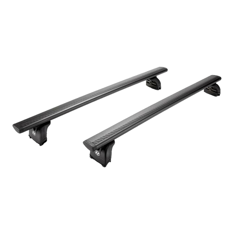
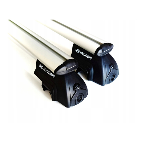
Crossbar Set
Model Year
2016 ~
Difficulty
( A )
Difficulty stated above reflects the minimum level of expertise required to install the accessory.
( A ) Customer ( B ) Dealer Technician ( C ) Master Technician
Note:
D3121 ADU01 (Panoramic Roof)
Language
REGULARLY CHECK THE TIGHTNESS BY PERFORMING A TUG ON THE CROSSBARS.
THEY SHOULD NOT MOVE. If crossbars move, see step 5 for proper tightening. Incorrect clamp tightness can cause crossbar
separation from vehicle resulting in product failure and vehicle damage. Serious physical injury may occur.
Loads must be evenly distributed and secured.
Any weight carried on the vehicle will adversely affect its handling particularly in cornering or in a cross wind and the vehicle should therefore be
driven with increased caution.
Only use NON-STRETCH tie down straps. Use of stretch elastic tie downs may cause loss of load, potential serious injury, and vehicle damage.
Denotes safety equipment required to be
used such as a mask, safety glasses,
gloves, and hearing protection.
Safety Glasses
Hearing Protection
Mask
Gloves
Denotes instructional steps necessary
to complete the process.
Denotes quality processes to be checked
prior to moving to the next step.
Denotes cautions to be taken to
avoid physical injury or electronic
component damage.
Denotes warnings that may lead to
serious physical injury or vehicle
damage.
Denotes specific tools that are necessary to
complete the step.
Denotes cautions to be taken to
avoid vehicle and component
damage.
Notes to the Installer:
1) Read the entire installation instructions prior to beginning the installation of this accessory.
2) Make sure the vehicle is completely clean before the accessory is installed.
3) Ensure the vehicle is properly protected in the area(s) that the accessory is to be installed.
4) To prevent vehicle damage, never place tools on top of painted surfaces, seats, dash pad, console or floor carpet/mats.
5) Always wear appropriate safety gear including gloves and safety glasses when required.
6) Confirm correct Crossbar Kit P/N with vehicle roof type application before installing.
Revision Date
08/22/2018
Page 1 of 6
4
4
Lock Cover (pre-installed on crossbars)
1
1
2
1
3
1
Wrench
1
Kit Overview
No.
Qty.
Description
Quick Reference Guide
5
Front Crossbar (longer)
Rear Crossbar (shorter)
Genuine Accessories
1
2
3
5
1102mm (43-3/8")
Compressed Inward
1152mm (45-3/8")
Compressed Inward
4
Service P/N: D3021 AU010
Service P/N: D3021 ADUS1
Revision Date
08/22/2018
Page 2 of 6
Genuine Accessories
Step Ladder and Clean Cloth
1
Coin
2
N
O
T
E
A. Clean the vehicle rails.
B. Verify the mounting holes are free of debris and/or obstructions.
N
O
T
E
A. Identify the front crossbar (longer bar).
B. Using a coin, turn each lock 90° counterclockwise to unlock covers.
C. Carefully pull the bottom of each locking cover, then slide the
covers downward as shown.
NOTE: The Left and Right orientation markings on the front crossbar
before installing on the vehicle.
CAUTION: Forcing the locking cover in or out of position may cause
damage to locking components. Ensure the lock is in proper position
before opening or closing the locking cover.
Wrench
3
Step Ladder and Wrench
4
N
O
T
E
CAUTION: Misaligned Wrench can cause bolt retainer to
not disengage which can result in damage to the Wrench
or assembly mount.
A. Position LH side of front crossbar (longer bar) over the LH side of
the vehicle side rail. Line up LH crossbar clamp pin with the #2* hole
position in the vehicle side rail.
B. Once aligned, slide end support on the RH side to its maximum
extended position. Lower the RH side of the front crossbar over
the RH side of the vehicle side rail and slide the RH end support
inward. Line up the RH crossbar lower clamp pin with the #2 hole
position in the vehicle side rail.
N
O
T
E
Load ratings are shown on the RH side clamp. Ensure the rating is on
the RH side of the vehicle, or the crossbar is incorrectly installed.
A. To tighten or loosen the clamp bolt; place the supplied Wrench over
the head of the clamp bolt and align the hex feature. The Wrench
will depress the bolt retainers allowing the clamp bolt to turn freely.
When tightening; the torque indicator arrows will align when the
proper torque value is achieved.
NOTE: Ensure the Wrench is parallel to bolt when tightening or
loosening clamp bolt. Tip: Hold Wrench shaft with one hand
while pushing the Wrench inward and turning with other hand.
Front Crossbar (LH detail shown)
Lower cover
Clamp Bolt
Bolt Retainers
Torque Indicator on
Wrench
Hex Feature on Wrench
#2*
#1
#1
#2*
* Denotes recommended
crossbar location
Front of
Vehicle
RH End Support in maximum
extended position
Lower
over rail
Orientation Markings
FORWARD
LH
RIGHT
FORWARD RH
To extend end support, pull by hand
Loosen
Tighten
Load Rating RH Side
1
2
3
4
Depress
Coin
Cover
Vehicle Rail
LH FORWARD
LEFT
Revision Date
08/22/2018
Page 3 of 6
N
O
T
E
Genuine Accessories
Step Ladder and Wrench
5
Step Ladder and Wrench
6
A. Check clamp bolts to ensure they are in locked position.
- The clamp bolt is in locked position when the notches in bolt are
engaged with bolt retainer.
- Use only provided Wrench for the clamping bolt.
N
O
T
E
A. Align the clamp pin with the mounting hole, then press and hold
clamp into position (with the clamp pin in the mounting hole), in order
to allow for the clamp bolt to engage when tightening.
B. Tighten the clamp pin by turning the clamping bolt clockwise - tighten
the bolt until proper 4Nm torque value is achieved with the provided
Wrench.
C. Repeat for opposite end of crossbar.
- Use only the provided Wrench for the clamping bolt. Any other wrench
may cause damage to the product.
NOTE: DO NOT over / under tighten.
Step Ladder and Coin
8
Load Rating Information is shown on the RH side clamp. Ensure the
Load Rating Information is displayed on the RH side of the vehicle.
A. Verify the front and rear crossbars are secure and clamp pins align with
the corresponding mounting holes.
B. Reinstall the locking covers.
C. Using a coin, lock the covers as shown.
- Turn the lock clockwise 90° to the locked position.
- Make sure that the lock has stopped in its 90° position and that the
cover is secure.
WARNING: Misaligned pin can cause clamp to break and can cause
crossbar separation from the vehicle resulting in product failure and
vehicle damage.
N
O
T
E
A. Repeat steps 2 - 6 for the rear crossbar in the #3* hole position in the
vehicle side rail.
Step Ladder and Wrench
7
N
O
T
E
INCORRECT
CORRECT
CORRECT
INCORRECT
Clamp
Bolt
Bolt Retainer
Rear Crossbar
Locked
Position
Raise locking cover
into position
Using a coin, turn Lock
clockwise to lock cover
4Nm
Proper torque is
achieved when arrows
on wrench are aligned.
#3*
#4
Load
Rating
Load
Rating
* Denotes recommended
crossbar location
Depress
#3*
#4
Revision Date
08/22/2018
Page 4 of 6
N
O
T
E
A. Fold the Quick Reference Guide in half.
B. Place the Quick Reference Guide and Wrench inside the vehicle's Glove
Box.
Genuine Accessories
9
Quick Reference
Guide
Wrench
Revision Date
08/22/2018
Page 5 of 6
Genuine Accessories
Visual Check
Items To Be Checked
Results Of The Check
With locking covers closed and clamp pins secure,
ensure the crossbars are in a locked position by
attempting to move the crossbars forward and
rearward.
Crossbars do not move and are tight.
Locking covers are locked and cannot be removed.
The locking covers should not move when in the
locked position.
Verify correct orientation of crossbar.
Crossbars correctly orientated.
Verify the rubber gaskets are seated without folds or
tucks.
Gaskets seated correctly.
Load rating markings are on RH side clamps.
Crossbar is correctly installed.
Revision Date
08/22/2018
Page 6 of 6

This manual suits for next models

1

Other Hyundai Automobile Accessories manuals

Hyundai AL100 99007 User manual

Hyundai

Hyundai AL100 99007 User manual

Hyundai J0F73 AU000 User manual

Hyundai

Hyundai J0F73 AU000 User manual

Hyundai 9999Z057196 User manual

Hyundai

Hyundai 9999Z057196 User manual

Hyundai D7211ADE00ST User manual

Hyundai

Hyundai D7211ADE00ST User manual

Hyundai J9F18 AU000 User manual

Hyundai

Hyundai J9F18 AU000 User manual

Hyundai CA100 User manual

Hyundai

Hyundai CA100 User manual

Hyundai K2F57 AC000 User manual

Hyundai

Hyundai K2F57 AC000 User manual

Hyundai CWF21 AU100 User manual

Hyundai

Hyundai CWF21 AU100 User manual

Hyundai 82302-3N700-W2R Reference manual

Hyundai

Hyundai 82302-3N700-W2R Reference manual

Hyundai C2017 ADU01 User manual

Hyundai

Hyundai C2017 ADU01 User manual

Hyundai 18-AT-008 Reference manual

Hyundai

Hyundai 18-AT-008 Reference manual

Hyundai HM-T008 User manual

Hyundai

Hyundai HM-T008 User manual

Hyundai ALU RELING User manual

Hyundai

Hyundai ALU RELING User manual

Hyundai 3X056 ADU00 User manual

Hyundai

Hyundai 3X056 ADU00 User manual

Hyundai 2S211ADE00ME User manual

Hyundai

Hyundai 2S211ADE00ME User manual

Hyundai Accent 2018 User manual

Hyundai

Hyundai Accent 2018 User manual

Hyundai S1370ADE00 User manual

Hyundai

Hyundai S1370ADE00 User manual

Hyundai U8780 2B000J9/J4 User manual

Hyundai

Hyundai U8780 2B000J9/J4 User manual

Hyundai BlueConnect User manual

Hyundai

Hyundai BlueConnect User manual

Hyundai L0F62 AU000 User manual

Hyundai

Hyundai L0F62 AU000 User manual

Hyundai 600 User manual

Hyundai

Hyundai 600 User manual

Hyundai CWF21 AU101 User manual

Hyundai

Hyundai CWF21 AU101 User manual

Hyundai D7211ADE00AL User manual

Hyundai

Hyundai D7211ADE00AL User manual

Hyundai HD78 User manual

Hyundai

Hyundai HD78 User manual

Popular Automobile Accessories manuals by other brands

Luverne 205760 installation instructions

Luverne

Luverne 205760 installation instructions

Stoneridge Optac 3 quick guide

Stoneridge

Stoneridge Optac 3 quick guide

Camcar 40000 manual

Camcar

Camcar 40000 manual

Yakima K1036 manual

Yakima

Yakima K1036 manual

Tactik Tube Doors Installation & use instructions

Tactik

Tactik Tube Doors Installation & use instructions

VBG Onspot Mounting instructions

VBG

VBG Onspot Mounting instructions

RSI SMARTCANOPY Fitment Instructions

RSI

RSI SMARTCANOPY Fitment Instructions

Rhino-Rack S512 manual

Rhino-Rack

Rhino-Rack S512 manual

Bolymin BE905A2 user manual

Bolymin

Bolymin BE905A2 user manual

BENDIX AUTOVUE FLC-20 Service data

BENDIX

BENDIX AUTOVUE FLC-20 Service data

Prorack P15 Fitting instructions

Prorack

Prorack P15 Fitting instructions

Century 3212 owner's manual

Century

Century 3212 owner's manual

Hypnotic Concepts SM-6873 installation instructions

Hypnotic Concepts

Hypnotic Concepts SM-6873 installation instructions

Baja Designs 448024 manual

Baja Designs

Baja Designs 448024 manual

AA Products APX2501 BLK instruction manual

AA Products

AA Products APX2501 BLK instruction manual

Fiamma CARAVAN XL A PRO Installation and usage instructions

Fiamma

Fiamma CARAVAN XL A PRO Installation and usage instructions

Twinny Load S 12 Fitting instructions

Twinny Load

Twinny Load S 12 Fitting instructions

Kemo M186 manual

Kemo

Kemo M186 manual

manuals.online logo
manuals.online logoBrands
  • About & Mission
  • Contact us
  • Privacy Policy
  • Terms and Conditions

Copyright 2025 Manuals.Online. All Rights Reserved.