TECSYSTEM CONV 4/420/A User manual
CONV 4/420/A
CONV 8/420/A
INSTRUCTION MANUAL
TECSYSTEM S.r.l.
20094 Corsico (MI)
CONV 4/420/A - CONV 8/420/A
TECSYSTEM S.r.l ®
R. 2.2 07/09/12

2CONV 4/420/A - CONV 8/420/A
TECSYSTEM S.r.l ®
INTRODUCTION TO MODULE CONV 4/420/A AND CONV 8/420/A
Add-on module CONV 4/420/A interacts via serial mode through 2 wires with NT935 moni-
toring device and it allows to take from output 4 4-20mA current signals referred to the 4
meter channels.
CONV 8/420/A has been designed for connection to NT538 monitoring device in order to
take 8 4-20mA current signals.
Opto-insulated serial connection between NTXXX and module.
To each NT935/NT538 monitoring device is possible to connect many add-on module.
For instance it will be possible to have an optioned monitoring device with 4.20 mA
outputs, relays bank for each channel and ModBus RTU interface simultaneously.

3
CONV 4/420/A - CONV 8/420/A
TECSYSTEM S.r.l ®
1) TECHNICAL SPECIFICATIONS
POWER SUPPLY
Rated voltage 24 VAC-DC ±10%
Vdc with reversible polarities
Highest absorption:
3VA CONV 4/420/A
5VA CONV 8/420/A
COMMUNICATION
Optoinsulated serial for monitoring units
NT935 (Model CONV 4/420/A) and
NT538 (Model CONV 8/420/A)
Highest distance 20 meters with 2x0,5mm2
shielded cable
INPUTS
Optoinsulated serial input for connection
to NT935 (Mod CONV 4/420/A)
Optoinsulated serial input for connection
to NT538 (Mod CONV 8/420/A)
USCITE
4 4.20mA outputs model CONV 4/420/A
8 4.20mA outputs model CONV 8/420/A
TESTS AND PERFORMANCES
Assembling in accordance with CE rules
Protection against electrical noises CEI-
EN50081-2/50082-2
Dielectric strength 2500 Vca for 1 min-
ute between serial input and 4-20mA
outputs and between serial input and
supply
Current/temperature range:
4.20mA/0-240°C
4.20mA/0-200°C (option)
4.20mA/-40 +200°C (option)
●Accuracy ± 1% full scale value
Ambient operating temperature -20°C to
+60°C
Humidity: 90% no-condensing
ABS self-extinguishing housing NORYL
94VO
Frontal in polycarbonate
Rail DIN mounting
Serial line self-diagnosis circuit
Option protection treatment of electronic
part
DISPLAYING AND DATA MANAGEMENT
1 green led for power supply line — ON
1 red led to show serial communication
problems — RS
DIMENSIONS
106x90mm DIN43880 – depth 58mm
(on DIN rail)
SOFTWARE RELEASE
V1-R1.4

4CONV 4/420/A - CONV 8/420/A
TECSYSTEM S.r.l ®
2) MOUNTING
Mount the meter inside the board fixing it on DIN EN50022 rail by the fixing hook on the
back of the housing.
The meter is designed to be mounted on the same board where NT935 or NT538 monitor-
ing devices are placed.
3) SUPPLY
CONV 4/420/A and CONV 8/420/A modules must be fed with a 24 VAC/DC ±10% voltage.
In case it is fed by a direct current source, it is not necessary to respect any connection
polarity.
4) CONNECTION TO NT935 / NT538 MONITORING DEVICE.
To connect CONV 4/420/A module to NT935 monitoring device or CONV 8/420/A module
to NT538 monitoring device it is necessary to use a 2-wire shielded cable with 0.5mm2
section.
Serial cable must be placed the farthest possible from power lines and shielding must be
one-sided grounded.
Yellow led RS FAULT is fixed on in case serial communication line should be cut out or
wrongly connected.
Control software has a special algorithm which can distinguish corrupted data from possi-
ble noises.
In case the transmission line should be extremely disturbed, RS FAULT led will blink.
In this case you have to verify the correct terminal board screw tightening as well as the
suitable cable positioning.

5
CONV 4/420/A - CONV 8/420/A
TECSYSTEM S.r.l ®
6) LUMINOUS INDICATORS
Lighting of ON led near the supply connector detects 24 Volts voltage supply.
RS led must be off with correct working conditions.
It turns on and stay fix in case the serial line should be cut out or in case of wrong con-
nection.
If it blinks, it means that the serial transmission is disturbed by strong external interfer-
ences; therefore it is necessary to verify that you are using a shielded cable, that it is one-
sided grounded and that it is placed the farthest possible from power lines or interference
sources.
5) 4.20 mA OUTPUT CONNECTION.
CONV 4/420/A module has 4 4.20 mA outputs whilst CONV 8/420/A module has 8 out-
puts.
To each 4.20 mA output it is possible to connect a read-out or acquisition device.
Admitted load impedance for each output goes from 0 to 500 ohm.
4-20 mA signal is referred to 0-240°C range with an accuracy of 1% compared to full
scale value.
It is possible to ask for a special calibration referred to a 0-200°C range.
For 0-240 range current temperature relation is the following:
Iout= (T/15)+4 (T= temperature in °C)
Example:
If T=100°C Iout= 100/15+4= 10,67 mA (±0.2 mA)
For 0-200 range, relation is: Iout= (T/12,5)+4 (T= temperature in °C)
For -40 +200 range, the relation is: Iout= (T/15)+1/015 (T= temperature in °C)
7) WORKING NOTES
To work, the module doesn’t need any programming since it gets all the necessary infor-
mation from NT935 / NT538 temperature control monitoring device.
4.20mA outputs are active-type; therefore they don’t need any additional supply.
Serial communication between temperature control monitoring device and 4.20 mA mod-
ule is active only when NT935 or NT538 are in temperature control working mode in one
of foreseen modes (Scan, Auto, Man e T.Max).
When other functions, such as programming, programming display and test relays are
activated, serial communication with the add-on module is temporarily disabled.
6CONV 4/420/A - CONV 8/420/A
TECSYSTEM S.r.l ®
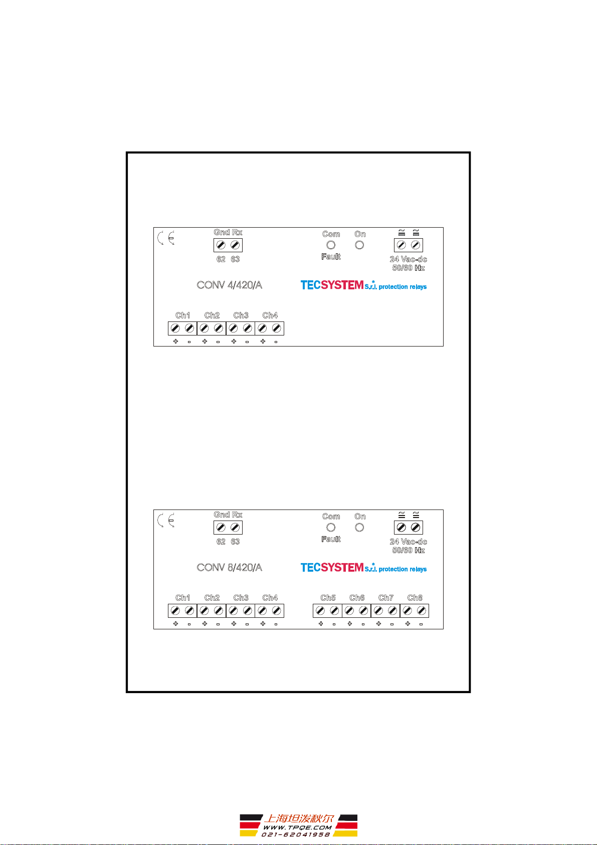
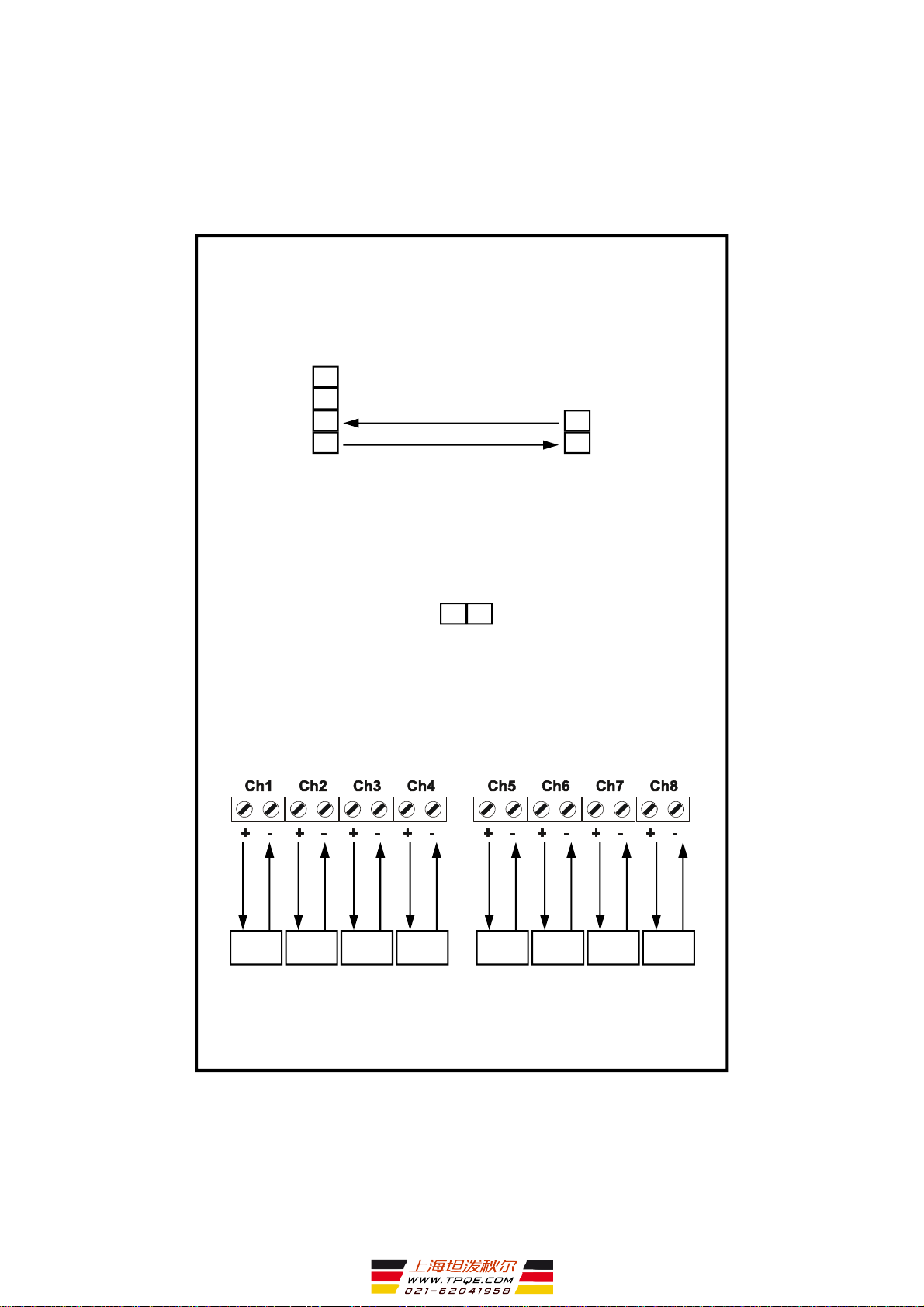
MODULE CONV 4/420/A
MODULE CONV 8/420/A
7
CONV 4/420/A - CONV 8/420/A
TECSYSTEM S.r.l ®
SERIAL LINE
62
61
60
63
GND RX
RX
GND TX
TX
62
63
GND RX
RX
NT935 / NT538 CONV 4/420/A
CONV 8/420/A
24VAC/DC
SUPPLY
4.20 mA OUTPUTS
Only for CONV 8/420/A
CONV 4/420/A AND CONV 8/420/A ELECTRICAL CONNECTIONS
Load 1 Load 2 Load 3 Load 4 Load 5 Load 6 Load 7 Load 8
8CONV 4/420/A - CONV 8/420/A
TECSYSTEM S.r.l ®
8) RULES FOR WARRANTY
The Product purchased is covered by manufacturer's warranty or the seller's terms and
conditions set forth in the "General Conditions of Sale Tecsystem srl", available at
www.tecsystem.it and / or purchase agreement.
The warranty is considered valid only when the product will be damaged by causes
attributable to TECSYSTEM srl, such as manufacturing or components defects.
The warranty is invalid if the Product proves tampered / modified, incorrectly connected,
because voltages outside the limits, non-compliance with the technical data for use and
assembly, as described in this instruction manual.
Any action about warranty is always at our factory in Corsico-MI, Italy as stated by the
" General Conditions of Sale Tecsystem srl ".
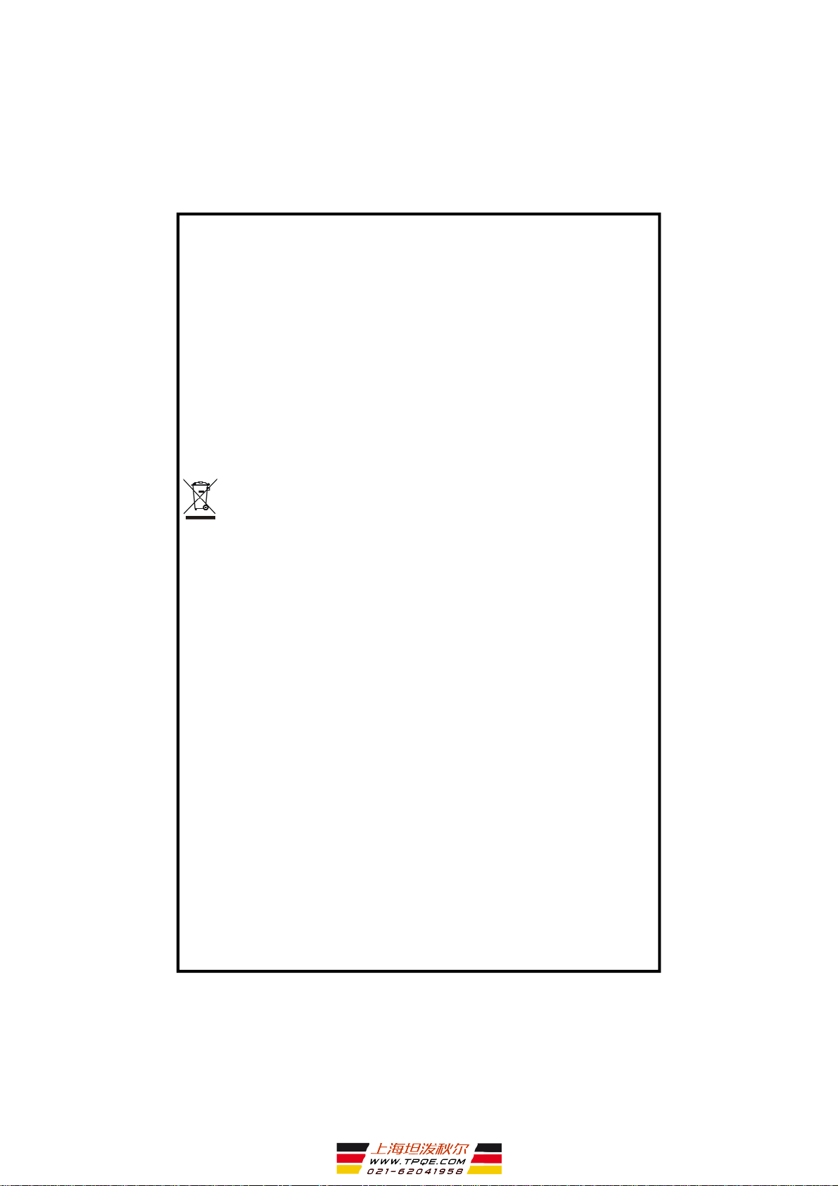
RAEE: This SYMBOL, shown on the unit, indicates that the waste must be subject to
"separate collection”. The end-user must send the unit to the “waste collection centers”, or
return the unit to the dealer against the purchase of a new equivalent device.
This manual suits for next models
1
Table of contents
Other TECSYSTEM Accessories manuals


Popular Accessories manuals by other brands


Coby
Coby 180BW instruction manual

Levana
Levana OmaSense quick start guide

SCENTED INTERIORS BY DESIGN
SCENTED INTERIORS BY DESIGN PRO-XL User manual & installation guide

Byron
Byron DB300 Installation and operation instruction

clare
clare ClareOne CLR-C1-PNL1 Installation sheet

SICK
SICK LMS4400 operating instructions


