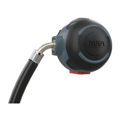
MSA ICU User manual

MSAsafety.com
Operating Manual
ICU/ICU-S
Integrated control unit
Order No. D4090048/0

© MSA 201All rights reserved.
English ....................................................... 3
Deutsch .................................................... 16
Français ................................................... 30
Italiano...................................................... 41
Nederlands............................................... 53
Español .................................................... 66
Norsk ........................................................ 77
MSA Europe GmbH
Schlüsselstrasse 12
CH-8645 Rapperswil-Jona
Switzerland
For local MSA contacts please go to our web
site www.MSAsafety.com.

3
For the Declaration of Conformity, please visit the product page on
MSAsafety.com'R&.

4
Notice!
Like any piece of complex equipment, this product will do the job
designed to do only if it is used and serviced in accordance with the
manufacturer’s instructions. This manual must be carefully read by all
individuals who have or will have the responsibility for using or servicing
the product.
The warranties made by MSA with respect to the product are voided if
the product is not used and serviced in accordance with the instructions
in this manual. Please protect yourself and your employees by following
them.
Before choosing and using this product, it is required to assess whether
this product is suitable for the applications intended. Choice and use are
beyond the control of MSA. Therefore, the liability MSA covers only the
consistent quality of this product.
The above does not alter statements regarding the warranties and
conditions of sale and deliveries of MSA.
The device is approved according to Directive 2014/34/EU.
The device may be used in potentially explosive areas (see 14).
The device must not be opened in potentially explosive areas. It is
protected by a rubber housing which must not be removed during use.
1 Application
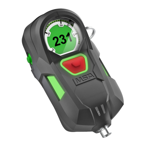
The integrated control unit ICU is an auxiliary device for users of
compressed air breathing apparatus. It informs the user about the
compressed air cylinder pressure, the remaining service time and the
temperature. Furthermore, the ICU has an integrated motion sensor
which gives an audible and visible alarm if the user is motionless. The
temperature indication is a measure for the average heat stress during
the intervention. It is not a thermometer.
2 Design
The ICU has a robust housing into which an electronic unit and a
mechanical pressure gauge are integrated. Both function independent of
each other. The mechanical pressure gauge has an analog indication,
i. e. with a needle on a luminescent scale. The electronic unit

5
is equipped with a display that can
also be illuminated and an audible
alarm. The device is operated with
three buttons (green mode button,
red alarm button and yellow reset
button). Power is supplied from a 9 V
battery. The ICU is designed to
continually monitor the reading of the
pressure transducer, even if the ICU
is switched off. This feature ensures
that the unit is activated immediately
upon pressurization by the cylinder.
However, this safety feature causes a
low but continuous consumption of
the battery. Therefore, the battery
needs to be replaced approximately
every 6 months.
Note:
The pressure indicated by the display may slightly differ from the
mechanical pressure gauge. For safety reasons the lower pressure
should be observed.
3 Technical Data
Dimensions: 145 mm height, 70 mm width, 50 mm depth
Weight: approx. 300 g
4 Battery Condition and Battery Change
4.1 Battery Condition
xThe 9 V battery has an operating time of approx. 50 hours. This time
depends strongly on the type and number of alarms given.
xThe battery status is indicated in three steps on the display.
xIf the battery level is low, alarm is given (see 7.2).
Note:
A new start is not possible with a discharged battery.

6
4.2 Battery Change
The device is only allowed to be used with the following battery type
(see chapter 13 for further details):
Alkaline Duracell MN1604 6LR61, except for Ultra series
3DQDVRQLF3RZHUOLQH
Application range: –30°C … +60°C:
It is recommended to replace the battery prior to the first use of the ICU.
A spare battery comes with the unit.
Attention: Do not change battery in explosive atmospheres!
xTo change the batteries, loosen the screws at the rear of the battery
compartment with the provided wrench for socket head cap screws.
xReplace the used battery with a new one (see type label in battery
compartment). Observe proper polarity and assure that the
compartment cover is closed watertight.
5 Assembly of the ICU
Note: This step is not required if the compressed air breathing apparatus
is supplied with the ICU assembled.
5.1 Assebly of the ICU to the BD 96
xPrior to use, the ICU must be assembled to the compressed air
breathing apparatus. First, the pressure gauge must be unscrewed
from the pressure gauge line.
xUnscrew the gauge with two spanner wrenches SW 14.
xApply a drop of medium-solid screw locking adhesive
(e. g. Loctite 243, Part No. D0011250) onto the thread of the ICU.
Screw the ICU into the pressure gauge line and counter the cap
screw with two spanner wrenches SW 14 with a torque of 15 Nm.

7
5.2 Assembly of the ICU to the BD 88
xPrior to use, the ICU must be assembled to the compressed air
breathing apparatus. To do this, the pressure reducer must be
disassembled from the carrying plate.
xUnscrew the pressure gauge line from the pressure reducer with a
spanner wrench SW 14.
xRemove the gasket with a suitable tool (e. g. wire hook) from the
pressure gauge connection, without damaging the sealing surface.
xInsert the new gasket that is provided in the ICU 88 set into the
pressure reducer.
xScrew the pressure gauge line with the ICU into the pressure reducer
with a torque of 20 Nm.
xReassemble pressure reducer onto carrying plate.
6 Operation and Switching Off
6.1 Putting the ICU into Operation
xThe ICU is put into operation automatically when the filled
compressed air cylinder(s) is opened.
xThen the device makes a self-test to check its proper condition. Here
the LEDs blink, the display briefly shows all available symbols and
the audible signal (Beeeep, pause, beep bop bop) sounds.
xThe device indicates the measured pressure on the LCD display and
the mechanical pressure gauge. It is ready for use.
xThe measured pressure is indicated on the display only for the first
3 ½ minutes. Thereafter, when in use, the display automatically
switches to remaining service time as standard display.
6.2 Switching Off
xTo switch off the ICU, the apparatus needs to be pressure-free. To do
this, close the cylinder valve(s) and release the pressure with the
lung governed demand valve (see Instructions for Use of compressed
air breathing apparatus).
xAfterwards the yellow button must be pushed twice within 2 seconds.
Once the device is turned off, a signal sounds (beep, pause, beep,
bop) and the LCD indicator and the LEDs turn off.
Note: The apparatus is considered pressure-free when the measured
pressure is less than 10 bar.

8
7 Use of the ICU
7.1 Monitor Function
The ICU measures the temperature, the motion status, the battery
status, the time, the cylinder pressure. Taking into consideration the
actual breathing, it calculates the remaining service time.
Note: The remaining service time is that time available to the user until
the retreat alarm sounds. This may be the pressure alarm
(usually 60 bar) or the retreat alarm entered manually at the work site
(see 7.5).
For determining the remaining service time the actual breathing rate of
the last 3 minutes is used.
The actual breathing rate is evaluated every 30 seconds and the
remaining service time is recalculated. If the breathing rate increases,
the remaining service time is reduced accordingly.
In order to have reliable data for the calculation of the remaining service
time, the apparatus must be in use for 3 ½ minutes, i. e. the device
cannot determine the remaining service time during the first 3 ½ minutes
of use. For this reason during the first 3 ½ minutes the display shows the
measured pressure. After 3 minutes there are reliable data for the
remaining service time.
This is shown when the LCD automatically displays the change from
pressure to remaining service time. In case of switched on apparatus
and no breathing rate (stand by) the LCD shows the cylinder pressure as
standard display. If then the green button is pushed for determination of
the remaining service time, the display will show three dashes (”---”).
The clock symbol during the remaining service time disappears briefly
every 10 seconds. This shows that the integrated real time clock is
functioning properly.
The optional PC software (see 7.7) permits changing the calculation
principle of the remaining service time from pressure alarm (e.g. 60 bar)
to alarm ”cylinder empty”. In this setting the remaining time is indicated
that is available to the user until the cylinder air is exhausted entirely.

9
Alarm LCD optical LED optical audible
150 bar 150 bar is lit green blinking beep-beep
100 bar 100 bar is lit green blinking beep-beep, pause,
beep-beep
60 bar, resp.
return to safety
pressure indication lit for
15 seconds, then not lit
blinking: red-red,
pause, red-red
alternatively
continuing
beep-beep, till
pressure drops
below 10 bar
Battery alarm half battery status symbol green blinking a beep every
8 seconds
Motion
prealarm
remaining service time
(after the first 3 minutes and
during use; at othertimes,
cylinder pressure)
slow red blinking getting louder
and different
tone succession
Motion
main alarm
cylinder pressure quick red blinking continuing
beep, beep, beep
Temperature
(> 65 °C)
illuminated temperature
display
green blinking continuous
beep-bop,
interval of 3 sec.
7.2 Alarm Display
The device displays the alarms differently. The previous table shows the
different variations.

10
7.3 Alarm Acknowledgement
After an alarm is given, it can be acknowledged by the user. The
following table shows the variations.
Alarm Acknowledgement
150 bar not necessary, since brief audible signal
100 bar not necessary, since brief audible signal
60 bar cannot be acknowledged
Returning
home alarm
can be acknowledged by pressing the yellow button
twice – other pressure alarms (60 bar or 100 bar)
sound again after acknowledgement
Battery alarm Replace battery after intervention.
Note: Battery capacity is good for a full intervention even with low-
battery alarm.
Motion prealarm move the ICU
Motion main alarm press yellow button twice
Temperature only through drop in temperature, i.e. removal of heat source
7.4 Manual Change of Display
xThe green button serves to display the various measured data.
xThis is accomplished by pressing the green button the appropriate
number of times within 15 seconds.
xThe following tables show the appropriate number of times for the
various data.
No. of times
green button
is pressed
LCD shows after 3 ½ minutes and use
0 (initial state) remaining service time display including clock symbol not lit
1 x press remaining service time display including clock symbol lit
2 x press pressure display lit
3 x press temperature lit
4 x press remaining service time display including clock symbol lit

11
No. of times
green button
is pressed
LCD shows before 3 ½ minutes or no consumption
0 (initial state) pressure display not lit
1 x press pressure display lit
2 x press temperature display lit
3 x press lit "---" with clock symbol
4 x press pressure display lit
Note:
If the mode button is not repressed within 15 seconds, the device
switches back to initial state (remaining service time display including
clock symbol, resp. pressure display not lit).
7.5 Retreat Alarm
xThe retreat alarm can be entered manually by the user.
xTo do this, the yellow button must be pressed without interruption for
2 seconds when the work site has been reached.
xStorage of this value in the memory is acknowledged by the device
with an audible signal.
Note:
The programmed value can be actualized by repressing the yellow button
later for 2 seconds (max. 3 times).
Explanation:
The ICU stores the pressure difference from opening the cylinder(s) until
the pressing of the yellow button (arrival at work site). This difference is
the air requirement for getting to the work site. According to fire fighting
regulations, double this air consumption must be planned for retreat.
Once the cylinder pressure has dropped to this value, the device gives
alarm to alert the user to start retreat.
Note:
The device will give a retreat alarm only if this is higher than 60 (e. g. at
80 bar). Otherwise only the 60 bar alarm will sound. The retreat alarm
can be acknowledged by pressing the yellow button twice. Independent
there of the latching 60 bar alarm, resp. the 100 bar alarm will sound.

12
7.6 Manual Alarm
xIn emergency situations the apparatus user can initiate the motion
main alarm himself.
xThis is done by pressing the red button.
Note:
The alarm can be initiated when the ICU is switched off (pressureless).
This is done by pressing the red button longer than ¼ seconds.
7.7 Data Transfer Mode
xThe device can transmit and receive data from a PC via an infrared
link.
xIn order to prepare the device for communication, it must be switched
off (see 6.2).
xBy pressing the yellow and green buttons without interrupting for
3-5 seconds, the ICU is ready to communicate.
xAn audible sound indicates readiness to communicate.
xThe successful transfer of data is documented by a blinking "Data" on
the LCD.
xIf the data transfer is interrupted or the data exchange is finished,
there is an audible sound after 30 seconds (beep-bop).
Note:
To transfer data between a PC and the ICU, a specially developed
software from MSA is required (see ordering information).
7.8 Calibration Mode
Important!
The ICU is already factory calibrated.
It is not allowed to get into the calibration mode.
8 Cleaning
xIf the device is badly soiled, it must be cleaned with lukewarm water
and detergent.
The high pressure connector must be sealed.
Note:
Do not use organic solvents like nitro dilution, alcohol, spirit, gasoline,
Tri, etc. for cleaning.

13
9 Malfunctions
xMalfunctions are indicated on the display with ”888”. Furthermore, a
permanent audible signal sounds.
The device must then be checked by MSA.
10 Maintenance and Test Intervals
Note:
To deactivate the motion alarm during maintenance the ICU key
(available as accessory, see Ordering Information) can be used. The
ICU must be switched off. Then the key is fitted above the display with
the fastening ring to the front. A recurring alarm sound indicates that the
key is fitted to the ICU and that the motion alarm is deactivated.
Type of work to be
performed
Prior to Release
for Use
Prior to Use After Use Every 6 Years
Battery Change
(see 4) X
Condensed Check
by user (see 6.1) X
Cleaning (see 8) X
Basic
Overhaul by manufacturer X
The device may not be repaired by the user. In case of a defect, it must
be replaced.
Repairs may only be performed by the manufacturer or authorized
service centers.
11 Key Version ICU-S
The key version ICU-S is identical to the ICU in functioning, as described
above. Only switching the unit on and off differs.
11.1 Putting the ICU-S into Operation
xOpening the filled compressed air cylinder(s) will put the ICU-S into
stand-by mode (mechanical pressure display is active).

14
Note:
In stand-by mode a warning sounds every 10 seconds to alert the user
to remove the key.
xAfter removal of the key, the device performs a self-chek to check
proper functioning. Here the LED blinks, the display briefly shows all
available symbols and an audible signal sounds (beeeep, pause,
beep bop).
xThe device now also shows the measured pressure on the display. It
is ready for use.
xThe cylinder pressure, however, is shown on the display only for the
first 3 ½ minutes. Thereafter, if the apparatus is in use, the LCD
automatically switches to remaining service time as standard display.
11.2 Switching Off the ICU-S
xIn order to switch off the ICU, the compressed air breathing
apparatus must be depressurized. To do this, close the compressed
air cylinder(s) and release the pressure with the lung governed
demand valve (see Instructions for Use of compressed air breathing
apparatus).
xThen place the key onto the ICU-S.
xAfterwards press the yellow button twice within 2 seconds. When the
ICU-S is turned off, a signal sounds (beeeep, pause, beep bop bop)
and the LCD and LED go off.
Note:
The apparatus is considered pressure-free when the measured pressure
is less than 10 bar.
12 RFID Tag version
For models with the optional RFID tag:
The RF power used to activate the RFID tag must be less than 2 W.
If the device is equipped with a RFID tag, it is located on the left side of
the device beneath the IR data port.

15
13 Ordering Information
Description Part No.
ICU D4090700
ICU for BD 96 and AirMaXX D4090700
ICU-S Keyversion 10016231
ICU-S - 40s 10122734-SP
ICU spare key D4090803
ICU software incl. infrared interface 10016232
The ICU is as well available for individual ATO (Assembled To Order)
configurations.
14 Marking, Certificates and Approvals
according to the Directive 2014/34/EU
Manufacturer: MSA Europe GmbH
Schlüsselstrasse 12
CH-8645 Rapperswil-Jona
ICU
EN 60079-0:2012, EN 60079-11:2012
II 1G Ex ia IIC T4 Ga
-30°C dTa d+60°C
Product:
Type of protection:
Marking:
Battery:
(C-Type Examination
Certificate:
T4: DURACELL MN1604 6LR61
(excluding Ultra series)
73DQDVRQLF3RZHUOLQH
BAS 99 ATEX 1141 X
Quality Assurance Notification: 0158 (DEKRA EXAM)
see Label
Year of Manufacture:
Serial Nr.: see Label
Special conditions for safe use:
For models with the optional RFID tag:
The RF power used to activate the RFID tag must be less than 2 W.

16
Informationen zur Konformitätserklärung finden Sie auf der Produktseite
unter MSAsafety.com'R&.

17
ACHTUNG!
Diese Gebrauchsanleitung weist auf die bestimmungsgemäße
Verwendung des Produktes hin und dient der Verhütung von Gefahren.
Sie muß gelesen und beachtet werden.
Die von MSA für dieses Produkt übernommene Garantie verfällt, wenn
es nicht entsprechend den MSA-Angaben eingesetzt bzw. verwendet,
gepflegt und kontrolliert wird.
Auswahl und Einsatz der Geräte unterliegen nicht dem Einfluss von
MSA, sondern obliegen dem Verwender. Unsere Haftung bezieht sich
daher nur auf gleichbleibende Qualität des Produktes.
Das Vorstehende ändert nicht die Angaben über Gewährleistung und
Haftung in den Verkaufs- und Lieferbedingungen von MSA.
Das Gerät ist nach Richtlinie 2014/34/EU zugelassen.
Das Gerät darf in explosionsgefährdeten Bereichen verwendet werden
(siehe 14).
Das Gerät darf in explosionsgefährdeten Bereichen nicht geöffnet
werden. Es ist durch ein Gummigehäuse geschützt, welches im Betrieb
nicht entfernt werden darf.
1 Einsatz
Die integrierte Kontrolleinheit ICU ist ein in Verbindung mit einem
Preßluftatmer verwendetes Hilfsmittel für den Gerätträger im Einsatz.
Sie informiert den Gerätträger über den Flaschendruck des
Pressluftatmers, die Resteinsatzzeit und die Temperatur. Darüber
hinaus ist ein Bewegungsmelder in das Gerät integriert, der im Falle von
Bewegungslosigkeit einen optischen und akustischen Alarm auslöst. Die
Temperaturanzeige ist ein Maß für die gemittelte Wärmebelastung
während des Einsatzes. Die ICU ist kein Thermometer.
2 Aufbau
Die ICU besteht aus einem robusten Gehäuse, in das eine elektronische
Einheit und ein mechanisches Manometer integriert sind. Beide Teile
arbeiten völlig unabhängig voneinander. Das mechanische Manometer
zeigt den gemessen Druck analog an, d.h. mittels Zeiger auf einem
nachleuchtenden Ziffernblatt. Die elektronische Einheit ist mit einem

18
beleuchtbaren Display und einer
akustischen Warneinrichtung aus-
gestattet. Die Bedienung des Gerätes
erfolgt mit drei Knöpfen (grüner Mode-,
roter Alarm und gelber Resetknopf).
Als Stromversorgung dient eine 9 V
Batterie. Die ICU ist so konzipiert, dass
ständig eine periodische Abfrage des
Drucksensors durch die Elektronik
erfolgt, auch wenn das Gerät
abgeschaltet ist. Damit wird bei
vorhandenem Flaschendruck die ICU
sofort aktiviert. Diese Sicherheits-
abfrage bedingt eine ständige, geringe
Stromentnahme der Batterie. Je nach
Umgebungstemperatur und
Einsatzbedingungen ist deshalb ein
Wechsel der Batterie nach
ca. 6 Monaten notwendig.
Hinweis:
Die Druckanzeigen von LCD-Display und mechanischem Manometer
können geringfügig differieren. Aus Sicherheitsgründen sollte als
Maßstab immer der geringere angezeigte Wert herangezogen werden.
3 Technische Daten
Maße ca. 145 mm Höhe x 70 mm Breite x 50 mm Tiefe
Gewicht ca. 300 g
4 Batteriezustand und Batteriewechsel
4.1 Batteriezustand
xDie eingesetzte 9 V Batterie erlaubt eine Einsatzzeit von ca.
50 Stunden. Dieser Wert hängt stark von der Art und Anzahl der
auftretenden Alarme ab.
xDer Batteriezustand wird im LCD-Display dauerhaft in 2 Stufen
angezeigt.
xBei kritischem Batteriezustand erfolgt Batteriealarm (vgl. 7.2).
Hinweis: Ein Neustart mit leerer Batterie ist nicht möglich.

19
4.2 Batteriewechsel
Das Gerät darf nur mit folgenden Batterietypen verwendet werden
(siehe Kap. 13 für weitere Details):
Alkaline Duracel MN1604 6LR61, ausgenommen Ultra Serie
3DQDVRQLF3RZHUOLQH
Einsatzbereich: –30°C … +60°C:
Vor der Inbetriebnahme der ICU wird empfohlen, die im Gerät
befindliche Batterie gegen die beiliegende Batterie auszutauschen.
Achtung:
Batteriewechsel nur in nicht ex-gefährdeten Bereichen zulässig!
xFür den Batteriewechsel müssen die auf der Rückseite befindlichen
Schrauben des Batteriefaches mit dem beiliegenden Inbusschlüssel
gelöst werden.
xDie verbrauchte Batterie ist durch eine neue Batterie gleichen Typs
(siehe Typenschild im Batteriefach) zu ersetzen. Hierbei ist darauf zu
achten, dass die Batterie entsprechend der angegebenen Polung
eingesetzt werden muß und der Batteriefachdeckel wasserdicht
montiert wird.
Hinweis zur Batterie-Entsorgung (gilt nur für Deutschland)
Gemäß § 11 Batteriegesetz – BattG – vom 25. Juni 2009 sind Sie als
Endverbraucher verpflichtet, Geräte-Batterien, die als Abfall anfallen, der
ordnungsgemäßen und umweltgerechten Entsorgung und Verwertung
zuzuführen. Eine Entsorgung über den gewöhnlichen Siedlungsabfall
(Hausmüll) ist nicht zulässig!
Die MSA Deutschland GmbH ist Mitglied des bundesweiten
GEMEINSAMEN RÜCKNAHMESYSTEM BATTERIEN (GRS Batterien).
Wir bitten Sie, die von uns in Verkehr gebrachten Geräte-Batterien über
die Sammelstellen des "GRS Batterien" zu entsorgen. Die Entsorgung
ist in diesem Fall für Sie kostenlos.

20
5 Montage der ICU
Hinweis:
Dieser Schritt entfällt, wenn die ICU vormontiert am Pressluftatmer
geliefert wurde.
5.1 Montage der ICU an BD 96
xVor dem Einsatz muß die ICU am Pressluftatmer befestigt werden.
Hierzu muss zunächst das Manometer aus der Manometerleitung
des Pressluftatmers geschraubt werden.
xMit zwei Gabelschlüsseln SW 14 muß die Verschraubung des
Manometers mit der Manometerleitung gelöst werden.
xEinen Tropfen mittelfesten Schraubensicherungskleber
(z. B. Loctite 243-Bestell-Nr.: D0011250) auf das Gewinde der ICU
geben. Gewinde der ICU in die Manometerleitung einschrauben und
die Überwurfmutter mit Hilfe von zwei Gabelschlüsseln SW 14 mit
einem Anziehmoment von 15 Nm kontern.
5.2 Montage der ICU an BD 88
xVor dem Einsatz muß die ICU am Pressluftatmer befestigt werden.
Hierzu muss der Druckminderer von der Tragevorrichtung demontiert
werden.
xMit einem Gabelschlüssel SW 14 muß die Verschraubung der
Manometerleitung und dem Druckminderer gelöst werden.
xDer Dichtring muss mit einem geeigneten Werkzeug
(z. B. Drahthaken) aus dem Manometeranschluss des
Druckminderers entfernt werden, ohne dabei die Dichtfläche zu
beschädigen.
xDer im Set mitgelieferte neue Dichtring wird in den Druckminderer
eingesetzt.
xDie Manometerleitung mit ICU wird mit einem Anziehmoment von
20 Nm im Druckminderer festgeschraubt.
xDer Druckminderer wird wieder auf der Tragevorrichtung montiert.
This manual suits for next models
1
Table of contents
Languages:
Other MSA Control Unit manuals
Popular Control Unit manuals by other brands

Task Force Tips
Task Force Tips OASIS HYDRANT ASSIST VALVE INSTRUCTIONS FOR SAFE OPERATION AND MAINTENANCE

EasyIO
EasyIO SystemView9 quick start guide

Asco
Asco 8314 Series Installation & maintenance instructions

Sentiotec
Sentiotec Pro B manual

ICP DAS USA
ICP DAS USA SG-785 user guide

Captron
Captron CHT4 Series Original operating instructions