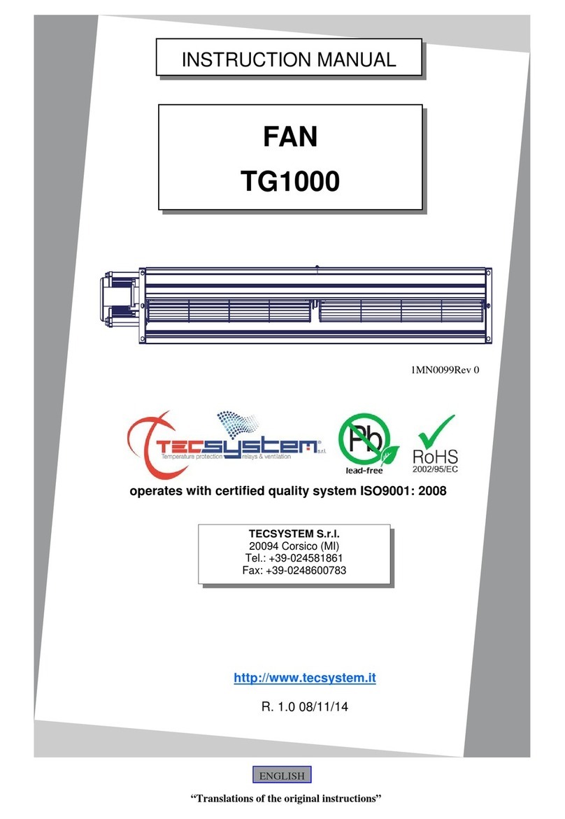
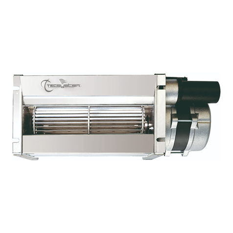
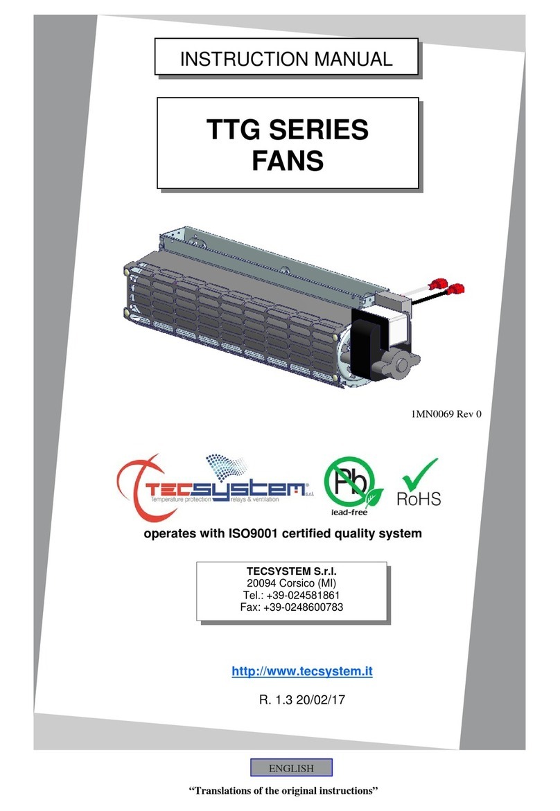
TECSYSTEM Bar 1200 User manual
Other TECSYSTEM Fan manuals
Popular Fan manuals by other brands
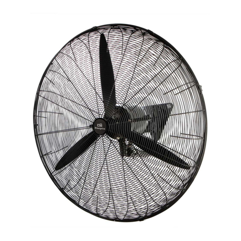
Orbegozo
Orbegozo WF 0165 instruction manual

Home Decorators Collection
Home Decorators Collection MAKENNA Use and care guide
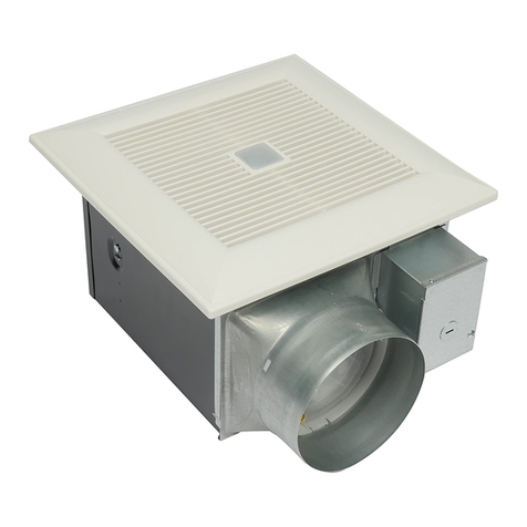
Panasonic
Panasonic FV-05-11VKS1 installation instructions
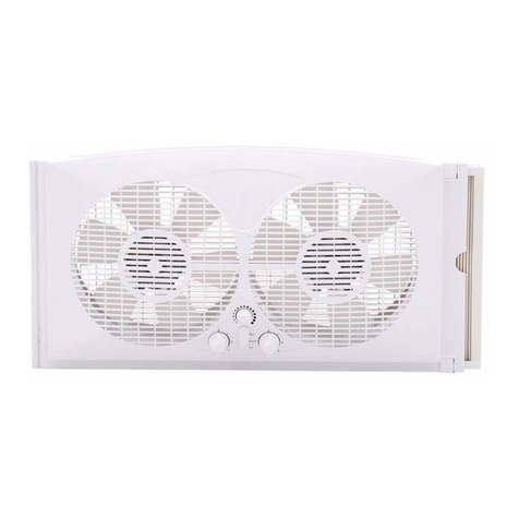
Pelonis
Pelonis FW23-A1 owner's manual
AirTech
AirTech Air+ WALL Installation & commissioning instructions

Gree
Gree FHBQGL-D1.5DA-T owner's manual

Kendal Lighting
Kendal Lighting AC-21454 Installation and operation manual
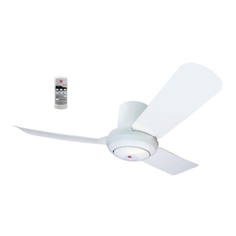
KDK
KDK S44XU Operating and installation instructions
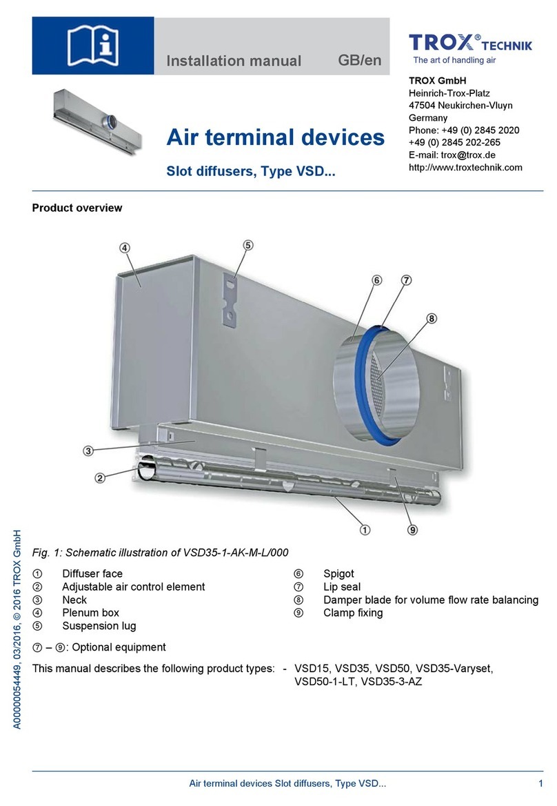
Trox
Trox VSD15 installation manual
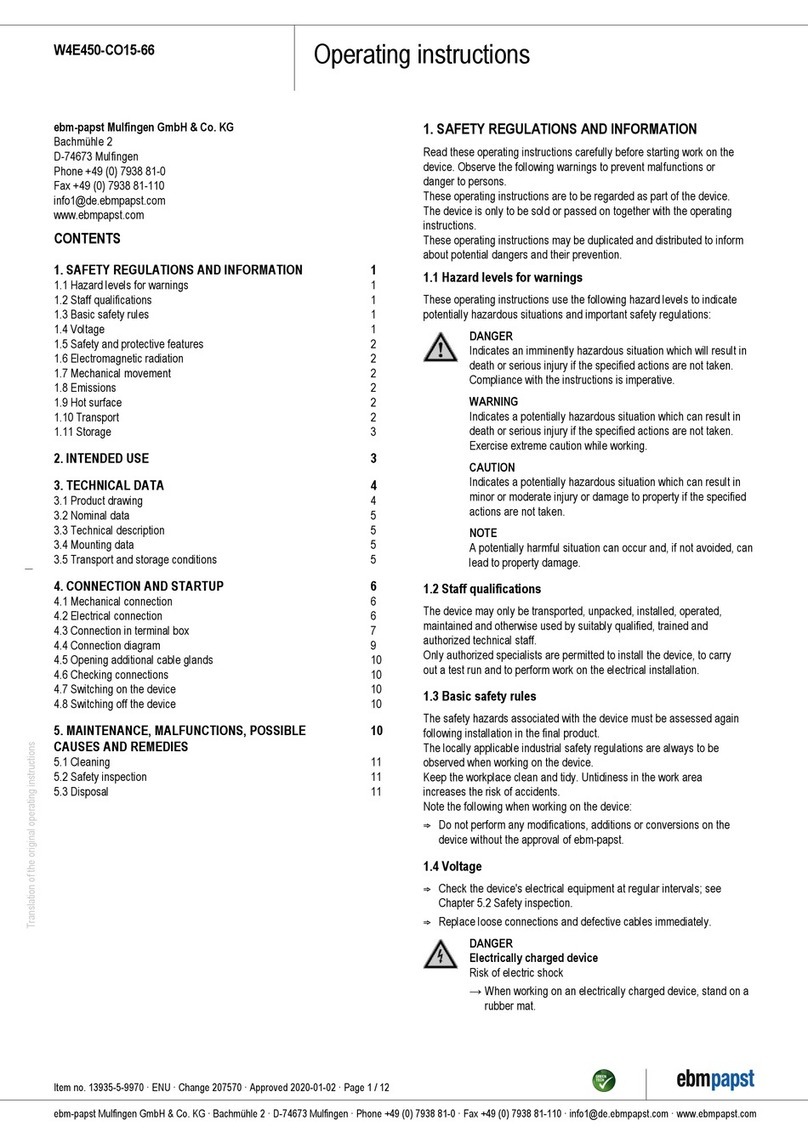
Ebmpapst
Ebmpapst W4E450-CO15-66 operating instructions
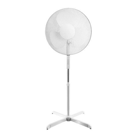
Hema
Hema 80.01.0055 Instructions for use

Swegon
Swegon GOLD SD Series Operation & maintenance instructions


