A LOOK AT SERVICE SAFETY
Genera Service Safety Precautions
7
•If a ground fault does not exist, go to Step 2.
•If a ground fault does exist, keep the power off.
WARNING! To avoid electric shock, electro-
cution and terminal venting with ignition, do
not energize a compressor that has a ground
fault. Mark and red tag the compressor to indi-
cate that there is a ground fault. Do not recon-
nect the power leads. Tape and insulate each
power lead separately. Proceed to Step 2. Do
not replace the compressor or energize the sys-
tem before performing Step 2.
Step 2:
Check for Water in the System
Once the compressor is cool to the touch, open the
system process valve slightly to see if any water
comes out of the system. WARNING! Opening the
system process valve while the compressor is hot
can cause severe burns from steam coming out of
the valve.
If ANY water comes out of the process valve, the
entire system must be replaced. See “D. Replacing a
Single-Wall Water-Utilizing System”.
If water does not come out of the process valve,
there is still a possibility that some water has leaked
into the refrigerant side of the system. To address
this possibility, determine if the system has a history
of losing refrigerant charge without a leak being
found or repaired.
If you find ANY indication of a history of losing
refrigerant charge without detection of a leak, this is
a sign that refrigerant has leaked in the water inside
the heat exchanger. The entire system must be
replaced. See “D. Replacing a Single-Wall Water-
Utilizing System”.
If you do not find any indication of a history of loss
of charge without detection of a leak, you still need
to install:
•a high-pressure cut-out which interrupts power
to ALL leads to the compressor, or
•an external pressure relief valve.
Also, if you found a ground fault in the compressor
in Step 1, replace the compressor before applying
power to the system.
D.
Rep acing a Sing e-Wa Water-Uti izing
System
When replacing a single-wall water-utilizing system,
replace the system with one that has:
•a double-wall heat exchanger(s), or
•a high-pressure cut-out which interrupts power
to ALL leads to the compressor, or
•an external pressure relief valve.
IX.
Start Capacitor Overheating
An overheated start capacitor can burst and spray or
splatter hot material which can cause burns. Apply-
ing voltage to a start capacitor for more than a few
seconds can cause the capacitor to overheat.
Check capacitors with a capacitance meter, and
never check a capacitor with the power on.
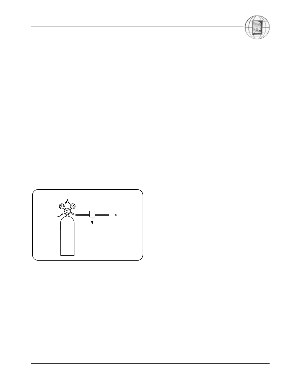
X.
System Evacuation
Never use a compressor to evacuate a system.
Instead, use a high vacuum pump specifically
designed for that purpose.
Never start the compressor while it is under deep
vacuum. Always break a vacuum with refrigerant
charge before energizing the compressor.
Failure to follow these instructions can damage the
hermetic terminal. As always, to avoid serious injury
or death from terminal venting with ignition, never
energize the compressor unless the protective termi-
nal cover is securely fastened.
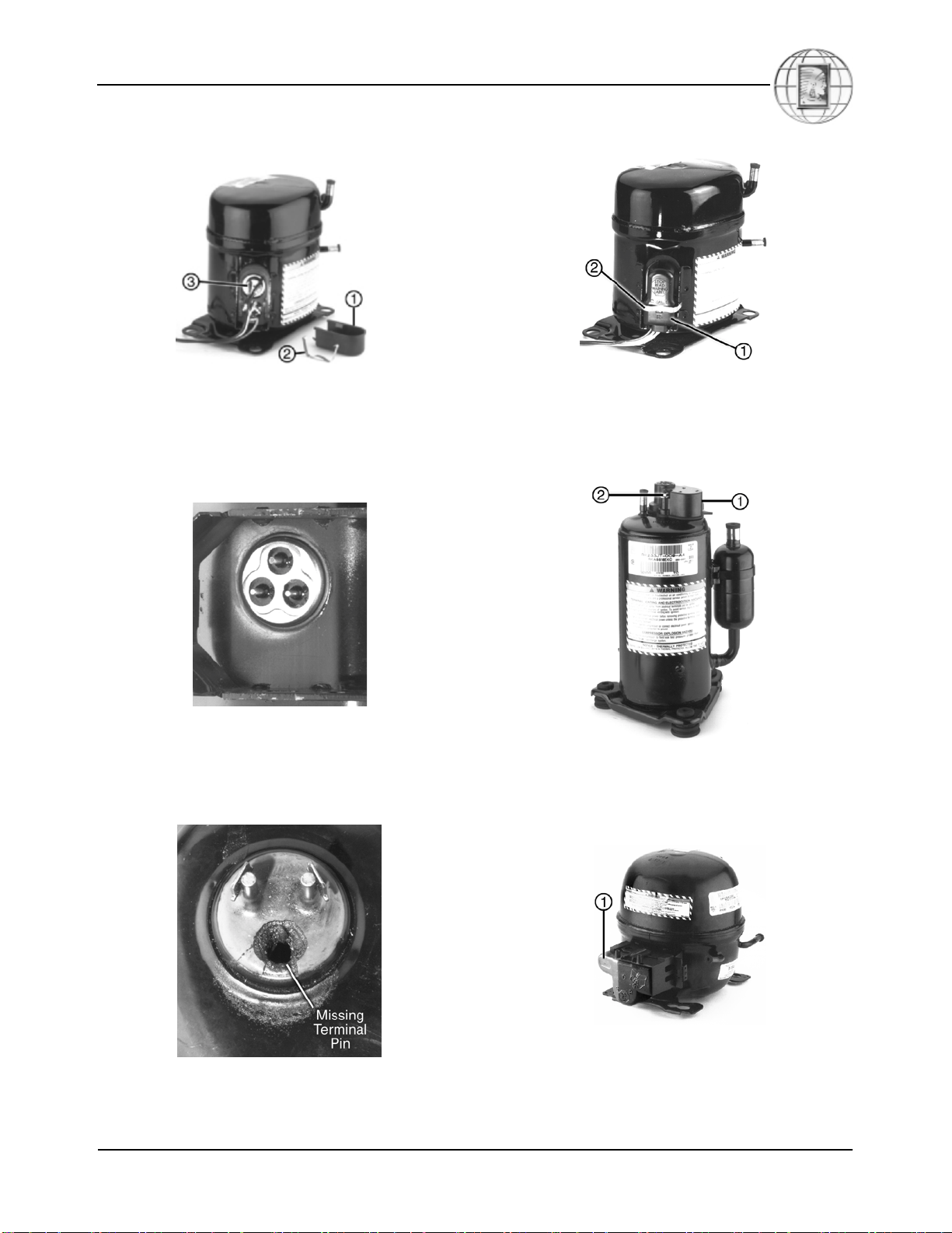
XI.
Fo ow the Labe s
Tecumseh Products Company compressors have
labels and markings with important information.
For your safety and the safety of others, read the
labels and markings on the product.