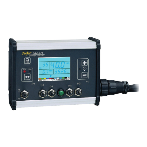
TeeJet UniPilot Pro User manual

UNIPILOT®PRO
ELECTRIC STEERING DEVICE
Installation Manual

Copyrights
© 2016 TeeJet Technologies. All rights reserved. No part of this document or the computer programs described in it may be reproduced, copied,
photocopied, translated, or reduced in any form or by any means, electronic or machine readable, recording or otherwise, without prior written
consent from TeeJet Technologies.
Trademarks
Unless otherwise noted, all other brand or product names are trademarks or registered trademarks of their respective companies or
organizations.
Limitation of Liability
TEEJET TECHNOLOGIES PROVIDES THIS MATERIAL “AS IS” WITHOUT WARRANTY OF ANY KIND, EITHER EXPRESSED OR IMPLIED.
NO COPYRIGHT LIABILITY OR PATENT IS ASSUMED. IN NO EVENT SHALL TEEJET TECHNOLOGIES BE LIABLE FOR ANY LOSS OF
BUSINESS, LOSS OF PROFIT, LOSS OF USE OR DATA, INTERRUPTION OF BUSINESS, OR FOR INDIRECT, SPECIAL, INCIDENTAL,
OR CONSEQUENTIAL DAMAGES OF ANY KIND, EVEN IF TEEJET TECHNOLOGIES HAS BEEN ADVISED OF SUCH DAMAGES ARISING
FROM TEEJET TECHNOLOGIES SOFTWARE.

i
98-05342 R1 EN
UniPilot®Pro
Table of Contents
IMPORTANT INFORMATION II
Introduction......................................................................................................................................................................................................ii
Legal Disclaimer..............................................................................................................................................................................................ii
Safety Information .........................................................................................................................................................................................ii
Safety Instructions ................................................................................................................................................................... ii
Warning Alerts......................................................................................................................................................................... iii
Caution Alerts ......................................................................................................................................................................... iv
INSTALLATION REQUIREMENTS IV
Standard Tool Requirements.....................................................................................................................................................................iv
Vehicle Requirements ..................................................................................................................................................................................iv
Vehicle Inspection.........................................................................................................................................................................................iv
CHAPTER 1 COMPONENTS 1
Supported Models .........................................................................................................................................................................................1
UniPilotPro Main Hardware Kit ................................................................................................................................................................1
UniPilotPro Switch Kit ..................................................................................................................................................................................2
CHAPTER 2 UNIPILOTPRO INSTALLATION 3
INSTALL THE MAIN GEAR ON THE STEERING WHEEL 3
Install the Main Gear around the Steering Column ...........................................................................................................................3
Examine Steering Column and Steering Wheel...................................................................................................................................4
ATTACH THE ANTIROTATION PIN 5
INSTALL THE ESD 6
CHAPTER 3 UNIPILOTPRO ANTIROTATION BRACKET INSTALLATION 7
UniPilotPro Anti-Rotation Bracket Installation Kit Overview.........................................................................................................7
UniPilotPro Anti-Rotation Bracket Installation Procedure..............................................................................................................8
CHAPTER 4 UNIPILOTPRO HARNESS INSTALLATION 9
Safety Notes......................................................................................................................................................................................................9
UniPilotPro Harness Connections Overview........................................................................................................................................9
UniPilotPro Harness Installation Procedure ...................................................................................................................................... 10
CHAPTER 5 ON/OFF SWITCH 11
On/O Switch ............................................................................................................................................................................................... 11
Led Lights ....................................................................................................................................................................................................... 11
CHAPTER 6 CARE AND MAINTENANCE 12

ii www.teejet.com
UniPilot®Pro
IMPORTANT INFORMATION
Introduction
The ESD (Electric Steering Device) is a high performance steering
actuator designed to provide high precision steering when coupled
to a GNSS automated steering system. The ESD was designed for
ease of installation, portability between vehicles and a long service
life. The ESD uses a reliable high torque DC motor and a robust
and simple gear drive for fast and responsive steering under all eld
steering conditions. The unique split gear design and quick-release
latch makes for an easy installation that does not require the removal
of the steering wheel so you gain time and are also able to easily
transfer your ESD between vehicles.
This manual provides the basic information and overview of the
installation procedure for installing the ESD steering actuator on a
vehicle. The ESD can be installed on many makes, models, and
types of vehicles. Read this manual prior to beginning the installation
as this manual provides the cautions and warnings that need to
be recognized and understood prior to installing or operating a
UniPilot Pro system.
This manual provides the instructions for the installation of the
components that come with this UniPilot Pro installation kit. The
installation is broken down into specic sections that may refer
to sub-kit assemblies that are part of this kit. These sub-kits will
come with their own instructions so refer to those when directed for
information on installing the sub-kit parts.
Prior to operating the UniPilot Pro system, be sure to also read and
understand the FieldPilot Pro & UniPilot Pro User Manual that comes
with the UniPilot Pro system. That manual provides the instructions
on how to operate the UniPilot Pro system with your guidance
system as well additional safety information.
Legal Disclaimer
NOTE: Read and follow ALL instructions in this manual carefully before installing or operating the UniPilot Pro system.
NOTE: Take careful note of the safety information in the Safety Information section of this manual and the additional safety messages
provided throughout this manual and any other supplemental material provided.
The manufacturer disclaims any liability for damage or injury that results from the failure to follow the instructions, cautions, and warnings set
forth herein. Please take special note of the following warnings:
1. There is NO obstacle avoidance system included with the
manufacturer’s product. The owner must always have a
human present in the operator’s seat of the vehicle when the
UniPilot Pro system is in use to look for obstacles including
people, animals, trees, ditches, buildings, etc. and take control of
the vehicle to manually avoid them if necessary.
2. The UniPilot Pro system does NOT control the speed of the
vehicle. The operator must always adjust the speed of the
vehicle manually so that it is operated at a safe speed that will
not cause the vehicle to roll over or go out of control.
3. The UniPilot Pro system will take over control of the vehicle’s
steering system when the UniPilot Pro system is activated
during: Testing, calibration, tuning, and automatic steering
operations. The vehicle’s steering axles, tracks, articulation
point, or wheels may move unpredictably when activated. Prior
to starting the vehicle and/or activating the UniPilot Pro system,
verify that all people and obstacles are clear of the vehicle to
prevent death, injury, or damage to property.
4. Use of the UniPilot Pro system is NOT permitted while the
vehicle is on public roads or in public areas. Verify that the
system is powered OFF before driving on roads or in public
areas.I
Safety Information
Safety Instructions
Read these safety instructions and the user’s instructions thoroughly, and follow the instructions.
• Only an operator who is fully authorized to drive the tractor can
make use of the UniPilot Pro system.
• The operator must not exceed the safe speed limit for the
terrain it is operating on.
• An operator must always be conscious of his actions when
operating the UniPilot Pro system.
• When installing the UniPilot Pro system do not force the
components as this can result in the components being
damaged.
• Always follow the instructions in the installation; operation; and
maintenance manual.
• Only an authorized party should install the UniPilot Pro system.
• Always carry out an inventory of the components delivered
to ensure all the correct components are present. Never use
replacement components. Only use original components.
• If there are any questions regarding the safe operation of the
UniPilot Pro system or the instructions in the manuals do not
hesitate to always contact the responsible expert.
• Always use the correct tools to install the UniPilot Pro system.
• Caution must be taken when installing the UniPilot Pro system
to prevent injury.
• Do not use or operate the UniPilot Pro system in unsafe
weather conditions. Do not use or operate the UniPilot Pro
system if the terrain is unsafe.

iii
98-05342 R1 EN
UniPilot®Pro
• It is not allowed for an unauthorized person to use or operate
the UniPilot Pro system.
• Before starting work activities, the operator must have sufcient
knowledge of procedures how operate the UniPilot Pro system
in a safe manner.
• When installing the UniPilot Pro system, all safety precautions
must be taken into account and it should not be used if there
are any parts loose, missing or damaged.
• Only an operator who has been trained or is experienced may
operate the UniPilot Pro system.
• Before using the UniPilot Pro system all functions must be
checked and controlled for their correct working order. When
there is any doubt, do not take any risks always consult an
expert.
• Before operating the UniPilot Pro system, control all functions
of the Presence Switch and conrm the settings to ensure it
functions correctly.
• Turning the UniPilot Pro system on and off must always happen
consciously following the correct prescribed procedures.
• If an abnormal phenomenon presents itself, for example
excessive vibrations or noise, then immediately turn off the
UniPilot Pro system and consult a responsible expert.
• When the UniPilot Pro system is being cleaned or when
maintenance takes place, it must be totally turned off and free of
any electrical currents.
• The operator of the UniPilot Pro system must have complete
knowledge about how to react in case of emergency.
• A trained expert must always carry out maintenance or repairs
on the UniPilot Pro system.
• During repair or replacement of components on the UniPilot Pro
system only original components must be used.
• Always wear correct prescribed personal protection equipment
during the use or cleaning or maintenance of the UniPilot Pro
system.
• Always use the recommended cleaning materials and
accessories when the UniPilot Pro system is cleaned.
• Every unsafe condition or situation on the UniPilot Pro system
must be reported to the responsible persons.
• Do not leave or place objects on or in the area of the
UniPilot Pro system.
Warning Alerts
The UniPilot Pro system installer and manufacturer disclaim any responsibility for damage or physical harm caused by the failure to adhere to
the following safety requirements:
• As the operator of the vehicle, you are responsible for its safe operation.
• The steering system is not designed to replace the vehicle’s operator.
NOTE: After the installation of the UniPilot Pro system, verify that all the screws, bolts, nuts, and cable connections are tight. Verify that all
the cables have been secured to prevent them from being damaged.
WARNING: To understand the potential hazards associated with
the operation of a ESD equipped vehicle, read the provided
documentation prior to installing or operating the UniPilot Pro
system.
WARNING: To prevent accidental death or injury from being run over
by the vehicle or automated motion of the steering system,
never leave the vehicle’s operator seat with the UniPilot Pro
system engaged.
WARNING: Movement of the Steering Control Module (SCM Pro)
relative to the vehicle may cause erratic steering and sudden
loss of vehicle control while in AutoSteer mode. Always keep

the Steering Control Module (SCM Pro) firmly secured to the
vehicle. Do not operate your UniPilot Pro system with a loose
SCM Pro.
WARNING: To prevent accidental death or injury from being run over
by the vehicle verify that area around the vehicle is clear of
people and obstacles before startup, calibration, tuning, or
use of the UniPilot Pro system.
WARNING: To prevent the accidental engagement of the UniPilot Pro
system and loss of vehicle control while driving on roads,
turn the ESD power switch to the OFF position or remove the
ESD from the steering column. Never drive on roads or in
public areas with the UniPilot Pro system powered up.
WARNING: The UniPilot Pro system is solely intended for agricultural
use. The systems should only be used with agricultural
vehicles and should not be used with any other type of
vehicle or for any other purposes. Unapproved applications
may result in loss of vehicle control resulting in injury or
death.

iv www.teejet.com
UniPilot®Pro
Caution Alerts
The UniPilot Pro system installer and manufacturer disclaim any responsibility for damage or physical harm caused by the failure to adhere to
the following safety requirements:
CAUTION: The UniPilot Pro system does not detect obstacles in the
vehicle’s path. The vehicle operator must observe the path
being driven and take over steering manually if an obstacle
must be avoided.
CAUTION: The UniPilot Pro system does not control the speed of the
vehicle. The operator must manually adjust the speed of the
vehicle to keep the vehicle safely under control.
CAUTION: To avoid possible damage to electronic circuits caused
by electrostatic discharge, never touch the contacts on the
SCM Pro electrical connectors at any time.
CAUTION: Make sure the assembly does not interfere with any of
the vehicle control levers on the steering column.
CAUTION: Make sure that the main gear race has properly engaged
on the three rollers before closing latch. If the race is not
engaged properly, you risk damaging the ESD and steering
wheel while the UniPilot Pro system is operating.
INSTALLATION REQUIREMENTS
Standard Tool Requirements
The installer is assumed to have a complete set of common installation tools including:
• 7/64" Allen Wrench
• 5/32" Allen Wrench
• 1/4" Open Wrench
• 1/4" Nut Driver
• Torque wrench 0 to 20 lb-in (0 to 2 Nm), for 5/32" hex bit
Vehicle Requirements
Prior to installing the UniPilot Pro system, verify the following items on the vehicle:
• The vehicles steering system is in good working order. Drive
the vehicle to verify this prior to beginning the installation. There
should be no play in the steering and the vehicle should turn
proportionally the same to the left and right.
• The vehicle’s electrical system and battery must be in good
working order.
• The vehicle should be fully cleaned before installing the
UniPilot Pro system. A clean vehicle will improve the overall
installation and cable routing.
If any issues are discovered with the vehicle, they must be repaired prior to beginning the UniPilot Pro installation by a qualied service
person for the vehicle.
NOTE: This installation manual, vehicle specific installation manuals, and sub-kit manuals contains valuable information for servicing the
UniPilot Pro system. After the installation is complete, store all of these manuals in a safe place for future reference.
Vehicle Inspection
Prior to installing the UniPilot Pro system, conrm that the vehicle and the vehicle’s steering system are in good working order by driving it
around. In addition, verify the following items:
• Verify that you can turn the steered wheels from lock to lock.
• Verify the vehicle steers straight and does not pull to one side
when driving in a straight line.
• Verify that there are no oil leaks.
• Check for loose or worn steering components.
If any part of the vehicle is not in working order, have the system serviced by a qualied technician prior to beginning the UniPilot Pro
installation procedure.

1
98-05342 R1 EN
UniPilot®Pro
CHAPTER 1 COMPONENTS
Supported Models
These instructions provide the suggested procedure for installing the UniPilot Pro system on qualied vehicles for the easiest installation and
best performance. This product is compatible with most vehicles with a three spoke steering wheel with hydrostatic power steering.
NOTE: The installer can install the UniPilot Pro system differently than how the manufacturer suggests; however the components that are
called out in this manual may not fit properly or the lengths of cables may not be long enough with alternative mounting solutions. If
the installer modifies the installation procedure, it is the responsibility of the installer to ensure all the components will work and that
any component with specific orientation and mounting requirements are met.
UniPilotPro Main Hardware Kit
NOTE: The kits listed below are used for illustrations purposes. Hardware Kit part numbers will vary.
This section describes the UniPilot Pro components required for a typical installation. The installation kit is organized into a main kit that
contains a “switch kit” subassembly. The Switch Kit contains the hardware that enables you to switch the UniPilot Pro system between
vehicles.
The UniPilot Pro installation may require the components listed below.
Figure 1: ESD Kit
1 2 3
Table 1: ESD Kit
Item Part # Description Qty
1 91-05023 Electric Steering Device, UniPilot Pro 1
2 91-05024 Switch Kit, UniPilot Pro 1
365-05246 UniPilot Pro Anti-rotation Bracket Kit 1
65-05250 Assy. Anti-Rotation Pin UniPilot Pro
98-05342 UniPilot Pro Installation Guide 1
The sub-kits that are required for the installation of the UniPilot Pro system are provided in this section. Use this section to verify that all the
sub-kits and parts required for the installation are available.
NOTE: All part numbers provided in this manual are subject to change without notice. They are provided as a reference at the time of this
writing. Always verify that the part numbers are still valid from your UniPilot Pro dealer if spare parts need to be ordered.

2www.teejet.com
UniPilot®Pro
UniPilotPro Switch Kit
The Switch Kit components enable the operator to move the ESD between vehicles.
NOTE: An anti-rotation bracket that fits your vehicle steering column is required to complete the UniPilot Pro installation. This bracket
varies by vehicle model and must be purchased separately. Contact your UniPilot Pro dealer for a list of supported vehicles and
available bracket kits.
Figure 2: UniPilot Pro Switch Kit Components
67
1
2
3
4
5
UniPilot Pro Switch Kit
Item Part # Description Qty
1 402-0019-02 Upper Ring 1
2 402-0024-03 5.75 x 0.50 Spacer 1
3 402-0024-04 5.75 ID x 0.25 Spacer 1
4 Consult Dealer Ring Cap Assembly 1
5 200-0621-01 Main Gear Assembly 1
6 200-0635-01 Hardware Kit 1
7808-0015-01
808-0039-01 Hex Keys (5/32" & 7/64") 1
NOTE: All part numbers provided in this manual are subject to change without notice. They are provided as a reference at the time of this
writing. Always verify that the part numbers are still valid from your UniPilot Pro dealer if spare parts need to be ordered.

3
98-05342 R1 EN
UniPilot®Pro
CHAPTER 2 UNIPILOTPRO INSTALLATION
The UniPilot Pro installation process is described below. A detailed process for each step is described in the following sections.
1. Install the Main Gear on the steering wheel
2. Attach the Anti-rotation Pin
3. Install the ESD
Refer to Installation Kit Components in the Components section to identify the parts used in this section.
INSTALL THE MAIN GEAR ON THE STEERING WHEEL
The goal of this section is the installation of the main gear on the steering wheel. Through the use of switch kits, main gears can be installed
and left on multiple vehicles allowing the user to move the ESD.
Install the Main Gear around the Steering Column
1. Remove the 2 hex screws from the Smaller section of the Main
Gear.
Figure 3: Main Gear Hex Screws
2. Remove the Smaller section by pulling downwards.
NOTE: Tolerances are tight, pull directly downwards on the
smaller section.
Figure 4: Main Gear Smaller Section
3. Install the larger section under the steering wheel around the
steering column. Install with the gear side on the top side, closest
to the steering wheel.
NOTE: Weave the gear around the steering wheel spokes
if necessary, certain columns may be too thick for the gear
opening.
Figure 5: Main Gear Installed
4. Reinstall the smaller section using care to push directly upwards
on the sector, this is a very tight t.
NOTE: To facilitate the fit between the two gear sections, you
may need to apply a drop of oil to assist in aligning the two
gear sections.
5. Reinstall and secure the 2 hex screws. At this point the main
gear is assembled around the steering column below the
steering wheel. The gear is free to move around and must now
be clamped to the steering wheel.

4www.teejet.com
UniPilot®Pro
Examine Steering Column and Steering Wheel
Examine the steering wheel underside to determine if a spacer is
necessary. A steering wheel with a soft covering material usually
requires installation of a spacer to avoid interference with the ESD
housing. Flat steering wheels also require the addition of a spacer to
prevent interference between the steering wheel and ESD when the
wheel is turned.
Install Spacer (If Needed)
Install the spacer around the steering column between the steering
wheel and the main gear. Flex the plastic spacer as needed to
clear the steering wheel spokes. The large chamfer on the outside
diameter of the spacer ring should be facing the main gear.
NOTE: Two spacers with different thicknesses are included in the
kit. Select the thinnest spacer that provides the sufficient
clearance between the steering wheel and the ESD.
Figure 6: Installing Spacers - Line up angles
Figure 7: Spacer Installation
Install the Clamp Ring
1. The gear is free to move around and must be now clamped to
the steering wheel. This procedure will install and center the ring
gear for typical 3 spoke shaped steering wheels.
2. Place the clamp ring on top of the steering wheel and install a
minimum of 6 hex screws. Install a screw on each side of every
spoke keeping the screws as close to the spokes as possible. At
this stage keep the screws fairly loose to allow for centering.
NOTE: Two lengths of screws are provided in the kit to
support different thicknesses of the steering wheel spokes.
Select the shorter of the two screws that still provides full
thread engagement.
3. With the main gear clamped loosely, rotate and move the gear
until 3 screws touch the three spokes evenly. Figure 9 shows the
main gear rotated counter-clockwise until three of the mounting
screws touch the steering wheel spokes evenly. This procedure
will help to automatically center the gear under the steering
wheel.
Figure 8: Installing Top Ring

5
98-05342 R1 EN
UniPilot®Pro
Figure 9: Centering Ring Gear
The red circles indicate which screws are touching the spokes
4. Check the installation by rotating the steering wheel and
watching for off-center movement of the main gear. Repeat the
centering process as necessary.
5. Tighten the screws with an Allen key. Torque to 6 in-lb (0.7 Nm).
Tighten the screws in a cross-pattern (as opposed to tightening
each screw in a clockwise or counter-clockwise order).
NOTE: Do not over-tighten the clamp ring screws. This may
cause the ring gear to warp or damage the steering wheel
spokes.
6. Check the installation again after tightening by rotating the
steering wheel and watching for off-center movement of the main
gear. Repeat the centering process as necessary.
7. Snap the plastic cover over the top ring.
Figure 10: Installing Plastic Cover
ATTACH THE ANTIROTATION PIN
1. Choose the desired ESD orientation. The ESD can be mounted
in any orientation the user chooses. Consider the following when
choosing an orientation:
• Ease of installing anti-rotation bracket.
• Access to the Power Switch.
• Avoid locations where a knee could accidently press the power
switch.
• Avoid blocking the vehicle’s steering column controls and
indicators.
• Cable routing with minimal obstruction in the cab.
2. Based on your preferred orientation, choose one of three
locations for the Anti-rotation Pin.
Figure 11: Anti-rotation Pin Kit

6www.teejet.com
UniPilot®Pro
Figure 12: Anti-rotation Pin Locations
Bottom Position
Three O’clock Position
Nine O’clock Position
3. Assemble the anti-rotation pin by inserting the long screw
through the metal sleeve provided.
4. Install the anti-rotation pin under the ESD in one of the three
positions and tighten to 100 in.lbs (11.3 Nm) using the 3/16" hex
key (Allen key) provided.
NOTE: The anti-rotation pin must always be kept tight to
avoid breakage or separation. Periodically check the anti-
rotation pin and confirm that it is tight. Always tighten to the
specified torque.
INSTALL THE ESD
This procedure describes the installation of the ESD to the Main Gear
1. Open the ESD release latch.
Figure 13: Release latch
Release Latch
2. Fit the ESD around the Main Gear so that the three ESD rollers
align on the Main Gear race.
NOTE: The plastic cover on the ESD can be used as a guide
to fit the bottom portion of the ESD to the V-rollers.
Figure 14: Roller Engagement
Rollers
Gear Face
3. Ensure that the main gear race has properly engaged the three
rollers before closing latch.
4. Rotate the ESD manually to ensure smooth rolling operation.

7
98-05342 R1 EN
UniPilot®Pro
CHAPTER 3 UNIPILOTPRO ANTIROTATION BRACKET INSTALLATION
The UniPilot Pro anti-rotation bracket is available through your dealer. It should be used for vehicles that are not supported with a custom
vehicle-specic bracket. Consult your UniPilot Pro dealer for a list of all available anti-rotation brackets. An Anti-rotation bracket is required to
complete the UniPilot Pro installation.
NOTE: A different bracket may be required depending on your specific vehicle. Contact your UniPilot Pro dealer for details.
NOTE: If you are installing a custom specific vehicle anti-rotation bracket, skip this section and refer to the instruction manual provided with
your vehicle specific anti-rotation bracket kit.
UniPilotPro Anti-Rotation Bracket Installation Kit Overview
To complete your UniPilot Pro installation and prevent the rotation of the ESD (Electric Steering Device), an anti-rotation bracket must be
mounted to the vehicle steering column just below the steering wheel. This chapter provides instructions for installing a universal bracket kit
that is available as an accessory through your FieldPilot Pro & UniPilot Pro dealer. Many other brackets are available to t specic vehicles
models and can be ordered through your FieldPilot Pro & UniPilot Pro dealer. Contact your dealer for details and availability for your vehicle
model.
The Typical universal bracket kit includes the components.
Figure 15: Typical Universal Bracket Kit
Table 2: Universal bracket kit components
Item Part # Description Qty
1 522-0001-01 Flange Bearing 1
2 203-0218-01 Fifth Wheel Slider 1
3 202-0216-01 Front Bracket 1
4 202-0232-01 Back Bracket (‘V’ shape) 1
5 514-0088-01 Clamping screws. Machine Screw Phillips 1/4 - 20 x 4" (Washers, Lock Washers and Nuts) 4
6 512-0029-01 Bolts 5/16 -18 x 3/4" (Slider Attaching Bolts) 2

8www.teejet.com
UniPilot®Pro
UniPilotPro Anti-Rotation Bracket Installation Procedure
NOTE: The ESD is attached to the steering wheel prior to installation of the bracket kit.
1. Make sure that you have all of the required parts. Figure 15
2. Attach front bracket to the fth wheel slider bracket using the two
bolts (slider attaching bolts). Tighten nger tight.
NOTE: The slider bracket will require adjustment once
installed on the steering column.
Figure 16: Slider Attachment Bolts
Front Bracket
Fifth Wheel Bracket
3. Place the ange bearing assembly over anti-rotation pin.
NOTE: It is important that the anti-rotation pin is placed
through the flange bearing before attaching the Fifth Wheel
Bracket
Figure 17: Anti-rotation Pin Engagement
Anti-rotation Pin
4. Attach the back bracket to the front bracket using the four
machine screws clamping the steering column between the front
and back brackets.
Figure 18: Back Bracket Installation
5. Tighten the clamping assembly.
6. Adjust the position of the fth wheel slider so the ange bearing
is approximately in the middle of the anti-rotation pin and tighten
the bolts (Slider attaching bolts).
Figure 19: Slider Bracket Engagement
7. The bracket installation is complete.

9
98-05342 R1 EN
UniPilot®Pro
CHAPTER 4 UNIPILOTPRO HARNESS INSTALLATION
Safety Notes
NOTE: The vehicle must be powered off during the installation of UniPilot Pro harness
NOTE: To prevent the system from any unexpected shut down while operating, check the cable insulation and cable connections to the other
instruments. Route the cables away from all sharp edges to prevent control wires from being pulled hard or damaged.
UniPilotPro Harness Connections Overview
The typical UniPilot Pro Harness installation includes the components shown below.
Figure 20: UniPilot Pro Harness Components
Aeros 9040
Aeros
Main Harness
45-05884
Matrix
Main Harness
45-05626
Matrix ProGS 840
Matrix ProGS 570
or
Terminator
45-08101
Terminator
45-08102
SCM Pro
Harness
45-10172
SCM Pro
78-08097 UniPilot Pro
Foot Switch
32-04020
UniPilot Pro
Harness
45-10166
Electric Steering
Device, UniPilot Pro
91-05023
UniPilot Pro
Anti-Rotation Bracket
Kit Generic
65-05246
to Ethernet Interface RJ45 connector
Seat Switch
Input
Bracket SCM Pro
Flat
65-05251
Assy. Anti Rotation
Pin UniPilot Pro
65-05250
45-05381
DC: xx/xx
Connectoto
(+12v)
Power Cable
45-05381

10 www.teejet.com
UniPilot®Pro
UniPilotPro Harness Installation Procedure
The UniPilot Pro system cable harness installation steps are described below. Follow them in order, referring to Figure 20 as necessary. This
procedure assumes that you have connected your Steering Control Module (SCM Pro) to your Aeros or Matrix Pro GS console. Refer to
FieldPilot Pro & UniPilot Pro documentation for further information.
1. Connect the ESD to UniPilot Pro Harness 30 pin connector to the SCM Pro and tighten the connector screw using a 1/4" nut driver.
Tighten to 15 to 20 in-lbs (1.7 to 2.2 Nm). Use only the recommended nut driver and do not over tighten.
Figure 21: Connect UniPilot Pro Harness to SCM Pro
2. Connect the UniPilot Pro Harness to the ESD. Carefully align the circular connector against the mating connector under the ESD and
rotate until it ts. Then rotate the external sleeve clockwise to lock the connector. To disassemble, rotate the outer connector sleeve
counterclockwise. Never force the connector.
Figure 22: UniPilot Pro Harness to ESD Connection
3. Route the cables in such a way to prevent damage.
4. Installation of the ESD is complete refer to the FieldPilot Pro & UniPilot Pro User Manual for vehicle setup and calibration and operation
instructions.

11
98-05342 R1 EN
UniPilot®Pro
CHAPTER 5 ON/OFF SWITCH
ESD is equipped with an On/Off switch and LED diagnostic lights. The following sections covers the function of the switch and the lights.
On/O Switch
The ESD is equipped with an On/Off switch. This allows the operator to disable the ESD unit without powering down the complete
UniPilot Pro system. Position the switch to the ○ [circle] to disable the ESD.
Figure 23: On/Off Switch
Led Lights
The ESD has 2 LED lights
• When a steering command is given to the ESD, light 1 will ash Yellow and when the wheel is turning.
• When the ESD is powered, light 2 will be a constant Green.
Figure 24: Led Lights
1
2

12 www.teejet.com
UniPilot®Pro
CHAPTER 6 CARE AND MAINTENANCE
This chapter describes the required care and maintenance for your UniPilot Pro system. Should you require repair services, spare parts or
warranty, contact your UniPilot Pro dealer. Only the factory or an authorized service center has the correct parts and training necessary to
service your UniPilot Pro system.
• Keep the anti-rotation pin tight at all times. Check the anti-rotation pin every 250 hours of operation or every six months, whichever
occurs rst, and tighten as necessary to the specied torque. Do not operate the ESD unit if the anti-rotation pin is loose.
• Keep the anti-rotation bracket well secured to the steering column at all times. Check the anti-rotation bracket every 250 hours of
operation or every six months, whichever occurs rst, and conrm that it is secure and all fasteners are tight. Tighten as necessary.
• Keep the Steering Control Module (SCM Pro) and associated brackets well secured to the vehicle at all times. Verify that the SCM Pro
is secure every 250 hours of operation or every six months, whichever occurs rst, and tighten as necessary. Do not operate the
UniPilot Pro system if the SCM Pro is not well secured. A detached SCM Pro may cause sudden loss of vehicle control while in
AutoSteer mode.
• Do not expose your Electric Steering Device (ESD) to water or rain. Store the ESD in a protected location. On open platform tractors,
remove it from the vehicle when not in use.
• Check all cables and electrical connectors every six months. Secure any loose cables using cable ties.
• Clean the outside surfaces of your ESD and the three guide rollers using a damp cloth. Do not apply spray cleaners, spray waxes, liquids
or lubricants such as WD-40. The use of any liquid cleaning agent or lubricant may damage the internal components of your ESD and
will void the factory warranty.
• Always clean the main gear and main gear race with a damp cloth to remove dust before installing the ESD to the steering wheel. This is
especially important when moving the ESD between vehicles.
• The ESD is manufactured with sealed bearings and self lubricating components and does not require lubrication. Do not apply oil, grease
or spray lubricants.


UNIPILOT®PRO
ELECTRIC STEERING DEVICE
www.teejet.com
Installation Manual
98-05342-EN-A4 R1 English
© TeeJet Technologies 2016
Table of contents
Other TeeJet Controllers manuals
Popular Controllers manuals by other brands

Datapath
Datapath Aetria WallControl VSN Series quick start guide

ABB
ABB ACS 502 Series Installation & start-up manual

DMX4ALL
DMX4ALL ArtNet-LED-Dimmer 4 MK2 user manual

Steren
Steren 920-050 instruction manual

CHAFFOTEAUX
CHAFFOTEAUX 3318597 Assembly and operation instructions

STI
STI RTQ Series instruction manual