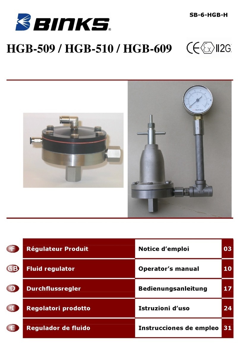
Binks HGB-509 Series User manual

SB-6-HGB-H
HGB-509 / HGB-510 / HGB-609
Régulateur Produit Notice d’emploi 03
Fluid regulator Operator’s manual 10
Durchflussregler Bedienungsanleitung 17
Regolatori prodotto Istruzioni d’uso 24
Regulador de fluido Instrucciones de empleo 31

SB-6-HGB-H 2/40
1
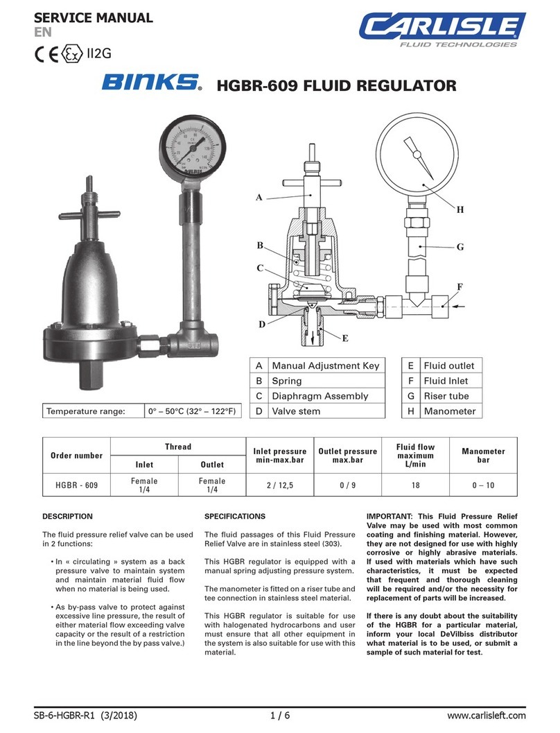
AClé de réglage
manuel Manual
Adjustment Key Stellschlüssel
Chiave per
regolazione manuale Clave de regulación
manual
BRessort Spring Feder Molla della
membrana Muelle de
membrana
CEnsemble
membrane Diaphragm Assy. Membransatz Membrana prodotto Membrana fluido
DClapet à bille Ball valve Kugelventil Sfera Rosca
EEntrée produit Fluid Inlet Produkteintritt Entrata prodotto Entrada del fluido
FSortie produit Fluid outlet Produktaustritt Salida prodotto Salida del fluido
GAir pilotage
pneumatique Pneumatic Air
command Pneumatiksteu-
erung Aria di comando Aire demando
HAir pilotage
rinçage Flushing air
command Spülsteuerung aria della
risciacquatura Aire del enjuague
JPiston et
rondelles de
réglage
Piston &
adjusting washer. Kolben &
Stellscheiben Piano e anello per
regolatore Plato y arandela
para regulador

Notice d’emploi
SB-6-HGB-H 3/40
CONSIGNES DE SECURITE
Important Lire soigneusement, suivre les instructions et les mesures de précautions avant de mettre en
marche l’équipement. L’employeur est chargé de mettre ces informations à la disposition de l’opérateur.
FEU ET EXPLOSION
Les solvants et les produits de protection peuvent être très inflammable, particulièrement lorsqu’ils sont
pulvérisés.
*Les stations de travail doivent être équipées de ventilation adéquate pour prévenir la formation de vapeurs
inflammables.
*Il n’est pas permis de fumer ou d’allumer une flamme dans les cabines de pulvérisation ou les zones de
préparation.
*Des extincteurs doivent être disponibles dans ces zones.
Les utilisateurs doivent se mettre en conformité avec les législations nationales et compagnies d’assurance
en ce qui concerne la ventilation, les précautions contre le feu, l’utilisation, la maintenance et l’entretien des
stations de travail.
HYDROCARBURES HALOGENES : L’utilisation de certains solvants (par exemple 111
Trichloroéthane et chlorure de Méthylène) peut entraîner des risques d’explosion par réaction chimique
avec des équipements contenant des pièces en aluminium, en zinc ou galvanisées. Lire la notice
d’utilisation du produit à pulvériser.
NE PAS UTILISER DES PRODUITS CONTENANT CES SOLVANTS SAUF AVEC DES
EQUIPEMENTS PREVUS A CET EFFET ET RECOMMANDES PAR LE FABRICANT .
ELECTRECITE STATIQUE . Elle est générée par la circulation des fluides dans les tuyauteries. Une
étincelle électrostatique, capable d’allumer certains solvants ou autres produits, peut être produite par des
débits produits importants. Nos régulateurs produit sont montés avec un corps et des raccords en acier
inoxydable afin d’assurer la continuité à la terre au travers du régulateur. Contrôler cette continuité à la
terre. La liaison électrique entre le régulateur et la terre doit être vérifiée avec un ohmmètre. Une résistance
inférieure à 106Ohms est recommandée.
EQUIPEMENTS DE PROTECTION
Vapeurs toxiques : Lors de leur pulvérisation, certains produits peuvent être nocifs, causer des irritations,
ou être la cause de trouble de santé. Il est nécessaire de lire attentivement toutes les étiquettes et données de
sécurité ou d’utilisation concernant le produit à pulvériser. Bien suivre les recommandations, et dans le
doute consulter le fournisseur de produit.
L’utilisation d’équipements de protection des voies respiratoires est recommandée chaque fois que l’on
pulvérise. Le type d’équipement de protection doit être compatible avec le produit pulvérisé et le niveau de
concentration.
Des équipements protégeant les yeux doivent être lors de pulvérisation ou du nettoyage du matériel ;
Le port de gants est recommandé lors de la pulvérisation ou du nettoyage du matériel avec certains solvants
ou produits.
FORMATION
Les opérateurs doivent être formés de façon adéquate pour une utilisation correcte et une maintenance de
cet équipement. Des cours de formation couvrant tous les aspects sont disponibles. Pour plus de détails,
consulter votre distributeur local.
Les instructions et les recommandations de sécurité contenues dans ce document et les étiquettes
concernant le produit à pulvériser, doivent être lues et comprises avant d’utiliser cet équipement.
UTILISATION INCORRECTE
La connexion ou l’utilisation d’accessoires ou de pièces détachées non recommandés ou non d’origine,
peuvent créer des situations dangereuses.
Avant de démonter l’équipement lors du nettoyage ou de la maintenance, fermer les alimentations d’air et
produit et purger les pressions résiduelles.
L’élimination des solvants ou produits usés doit être faite de façon légal. L’incinération peut provoquer des
fumées toxiques. L’évacuation des solvants ou produits usés doit être conduite en accord avec les
législations en vigueur.
Les matériaux utilisés pour produire cet équipement sont résistants aux solvants sous réserves des
recommandations liées aux hydrocarbures.
Ne pas mettre les régulateurs ou manomètres dans une machine de nettoyage de pistolet ou de l’immerger
dans du solvant, les manomètres ou les joints peuvent être endommagés.
Les solvants utilisés dans les machines à laver les pistolets doivent être régulièrement contrôlés afin
d’assurer que l’équipement n’est pas nettoyé avec du produit contaminé. Suivre précisément les
recommandations du fabricant de machines.

SB-6-HGB-H 4/40
UTILISATION
Avec réglage manuel ou avec pilotage pneumatique, ces régulateurs permettent d'alimenter en
produit sous pression constante un ou deux pistolets, bille inoxydable avec ressort de rappel en
acier inoxydable et siège « Perlast » pour application peinture faible viscosité et régulation à faible
hystérésis (consigne pression régulée précise).
CARACTERISTIQUES
Filetage
Type
Rég Références Entrée Sortie
Pression
d’entrée
min-max.bar
Pression
de sortie
max.bar
Débit
maximum
L/min
Plage du
manomètre
bar
HGB-509-5-R38 2 - 12,5 5 13 Sans
HGB-609-1.2-R38 1 - 8 1.2 8,3 0 - 2,5
HGB-609-5-R38 2 - 12,5 5 13 0 - 6
Manuel
ressort
HGB-609-9-R38
Femelle
3/8 BSP
Male
3/8NPS/
BSP 3 - 15 9 13 0 - 10
HGB-510-R1 2 - 15 15 1,6 (buse 1.1mm) Sans
HGB-510-R2 1 - 15 7 1,3 (buse 1.1mm) Sans
HGB-510-R4
Femelle
1/4 BSP Femelle
1/4 BSP 1 - 15 4 0,8 (buse 1.1mm) Sans
HGB-510-R1-CO 2 - 15 15 1,6 (buse 1.1mm) Sans
HGB-510-R2-CO 1 - 15 7 1,3 (buse 1.1mm) Sans
Ajustement
pneumatique
HGB-510-R4-CO
Male
3/8NPS/
BSP
Femelle
3/8 NPS 1 - 15 4 0,8 (buse 1.1mm) Sans
Tous les passages produit sont en acier inoxydable 303, membrane à base Téflon, coiffes en
aluminium nickelée (manuel) ou anodisées (piloté).
Les régulateurs HGB-609 sont équipés en sortie d’un té, d’une rehausse en acier inoxydable et
d’un manomètre, l’étanchéité des raccordements entre les éléments doit être conservée afin de
protéger le manomètre. Voir détail en accessoires.
IMPORTANT : Ces régulateurs peuvent être utilisés avec la plupart des produits de revêtement et
de finition. Cependant, ils ne sont pas conçus pour être utilisés avec des produits hautement
corrosifs ou abrasifs. Dans ce cas, il est recommandé‚de nettoyer fréquemment et entièrement le
régulateur et/ou de remplacer les pièces plus souvent.
DECLARATION DE CONFORMITE CE
Nous : ITW Surfaces & Finition, 163-171 Av des Auréats, 26014 Valence France, en tant que
fabricant du régulateur produit modèle HGB-510/509/609, déclarons, sous notre entière
responsabilité, que le matériel auquel ce document se rapporte est conforme aux normes et
documents réglementaires suivants :
EN 292-1 Parties 1 & 2: 1991, EN 1953 : 1999 ; et est donc conforme aux exigences de
protection de la Directive Européenne 98/37/EC relative à la directive sur la sécurité des
machines.
Ces accessoires sont classifiés en tant que composants, par la Directive ATEX-94/9/EC :
Appareils et systèmes de protection destinés à être utilisés en atmosphères explosives, et sont
en conformité avec les articles de cette directive, niveau II 2 G.
Directeur : Claude FERRET
ITW Surfaces & Finition se réserve le droit de modifier
les spécifications des équipements sans préavis.

SB-6-HGB-H 5/40
INSTALLATION
Les régulateurs HGB doivent être positionnés de préférence horizontalement pour éviter que le
produit chargé dépose en fond. Le tube de rehausse et le manomètre doivent être positionnés
verticalement. Le manomètre sera ainsi protégé par l'air restant dans le tube de rehausse. Toute
fuite aux raccordements du tube ou du manomètre sont à supprimer sous peine d’endommager
le manomètre.
Brancher la tuyauterie d’alimentation produit, venant d’une pompe ou d’un réservoir sous
pression, au bas du régulateur sur le raccord d’entrée filetage 1/4" BSP ou 3/8’’BSP/NPS
universel. Voir en fonction des versions page 4.
Brancher la tuyauterie d’alimentation en pression produit régulée vers un ou plusieurs pistolets à
partir du raccord de sortie en position latérale filetage 1/4" ou 3/8’’en fonction des versions voir
page 4. Le raccord de sortie est un écrou tournant pour la version « CO ».
Le régulateur doit être mis à la terre afin de dissiper les charges électrostatiques pouvant être
créé par les débits produits ou air. Ceci peut être réalisé en intégrant une cosse relié à un fil de
terre au dessous d’une vis Rep.3A ou 3B. Vérifier la continuité à la terre du régulateur avec un
ohmmètre, une résistance inférieure à 106ohms est recommandée.
Lors de la mise en marche assurez-vous de n’avoir aucune poche d’air sous la membrane du
régulateur ce qui pourrait avoir une influence sur la précision de la régulation pour une
utilisation à faible débit.
ATTENTION
Il est recommandé pour une première mise en route d’une installation que la ligne
d'alimentation produit ne passe pas à travers le régulateur, afin d’éviter d’encrasser celui ci et
de mettre des impuretés ou des copeaux sur le siège de valve du régulateur. L’UTILISATION
D’UN FILTRE en ligne est conseillé.
OPERATIONS
Régulateur manuel
Le réglage de pression produit ; se fait à l'aide de la clé
spécifique. (Fig A). Insérer le carré d’entraînement de la
clé dans le trou situé au dessus du régulateur. Visser pour
augmenter la pression, dévisser pour la diminuer.
Position rinçage en ouverture maximum, introduire la
partie cylindrique de la clé et visser la clé au maximum
pour descendre la tige en appui sur le porte membrane et
ainsi ouvrir le régulateur au maximum pour un rinçage
optimum
Régulateur pneumatique
Dans les modèles HGB-510-R1, R2 ou R4.
La pression produit régulée est ajustée grâce à une pression
d’air de pilotage venant d’un régulateur annexe, pour cela
installer le tube d’air sur le raccord en haut sur le couvercle
du régulateur.
Il est conseillé de monter le régulateur d’air au plus prés du
régulateur produit afin d’obtenir une régulation optimum, si
l’installation ne le permet pas, la création d’une fuite d’air
minimale sur le tube Rilsan à l’entrée du raccord de
pilotage assurera une réactivité maximale du régulateur
d’air. Position de rinçage en ouverture maximale, alimenter
le raccord en air de commande de rinçage pour ouverture
totale.
Attention : LA PRESSION DE COMMANDE DE RINCAGE DOIT ETRE SUPERIEURE
DE 1 BAR MAX. PAR RAPPORT A LA PRESSION D’ALIMENTATION DU SOLVANT.
Fig A Fig B

SB-6-HGB-H 6/40
Note : La purge de l’air du circuit de rinçage est obligatoire une fois l’opération effectuée afin de
revenir au réglage du pilotage initial.
Pour vous permettre d’identifier les modèles de régulateur entre « R1, R2 et R4 » une flèche
marquée sur le couvercle se trouvera soit en face le raccord d’entrée d’air de commande de
rinçage pour un modèle R1, soit en face de l’inscription 1/ 4 ou 1/ 2 se trouvant sur le corps
intermédiaire pour les modèles R4 ou R2. Lors du remontage de votre régulateur, il est nécessaire
de s’assurer de la position de la flèche par rapport au corps intermédiaire.
LISTE DES PIECES DETACHEES
Se référer à la vue éclatée pour la disposition des pièces.
Rep. Référence Désignation des articles Qté
1HGB-404-1 Clé de réglage manuel 1
2HGB-28 Coiffe du régulateur 1
3A
3B S-1309-H
S-1330-H Pour HGB-509-5-R38 et 609-x-R38, Vis M5 * 16
Pour HGB-510-R1, R2 et R4, ou (CO), vis M5 * 25 6
4HGB-408-H Ensemble vis de réglage 1
5HGB-7 Ecrou de réglage 1
6HGB-403-H Ensemble tige 1
7HGB-13-H
HGB-42
HGB-43
Ressort de membrane pour HGB-509-5-R38 et HGB-609-5-R38.
Ressort de membrane pour HGB-609-1.2-R38.
Ressort de membrane pour HGB-609-9-R38. 1
8A
8B S-24383
SSP-6462 Raccord droit M5 pour tube rilsan dia 2.7 *4 mm
Raccord coudé M5 pour tube rilsan dia 2.7*4 mm 1
1
9HGB-54 Couvercle pour HGB-510 1
10 HGB-55-K Membrane air pour HGB-510 1
11R1
11R2
11R4
HGB-67
HGB-56
HGB-63
Plateau suiveur pour HGB-510-R1 ou R1CO
Plateau suiveur pour HGB-510-R2 ou R2CO
Plateau suiveur pour HGB-510-R4 ou R4CO 1
12
12b HGB-68
HGB-64 Rondelle intermédiaire pour régulateur rapport R2, R4
Rondelle intermédiaire pour régulateur rapport R4 1
13 HGB-57-1 Corps intermédiaire 1
14m
14RHGB-422
HGB-424 Ensemble Membrane produit pour HGB-509, 609.
Ensemble membrane pour HGB-510-R1/2/4 ou 1CO/2CO/4CO. 1
15 Corps de régulateur 1
16 HGB-426-CO
HGB-426
HGB-426-R38
Kit valve bille ressort avec raccord d’entrée 3/8’’BSP/NPS Male.
Kit valve bille ressort avec raccord d’entrée 1/4’’BSP femelle.
Kit valve bille ressort avec raccord d’entrée 3/8’’BSP/NPS Femelle. 1
17 S-28216 Joint 1
18 HGB-62 Joints Téflon 1 / 2
19 HGB-61
HGB-81
HGB-82
Raccord sortie produit pour HGB-510-Rx, 1/4’’Femelle
Raccord sortie produit pour HGB-509-5-R38, 3/8’’male universel
Raccord sortie produit pour HGB-609-xx-R38, 1/4’’male BSP 1
20 HGB-49 Buse de raccord de sortie produit pour HGB-510-Rx-CO. 1
21 HC-1000 Ecrou tournant 3/8’’pour HGB-510-Rx-CO 1
22 HGB-60
HGB-59
HGB-80
Raccord entrée produit Femelle 1/4’’BSP pour HGB-510-Rx
Raccord entrée produit Male 3/8’’universel pour HGB-510-Rx-CO
Raccord entrée produit Femelle 3/8’’BSP pour HGB-509/609-R38 1

SB-6-HGB-H 7/40

SB-6-HGB-H 8/40
ENTRETIEN PREVENTIF
Un nettoyage périodique du régulateur à l'aide d'un solvant adapté est recommandé.
Pour le nettoyage de la ligne et du régulateur, respecter les points suivants :
1. Couper la pression.
2. Mettre le régulateur en position rinçage ouverture maximum. (Voir chapitre Opération
rinçage.)
3. Chasser le produit en sens inverse à travers la ligne régulée en introduisant une pression d'air.
Cela peut être réalisé par le pistolet manuel relier au réseau d’air en desserrant la bague de
chapeau d'air, en tenant un chiffon sur le chapeau et en actionnant la gâchette. L’air entrera en
chemin inverse au travers de la buse du pistolet et repoussera le produit sur la ligne produit.
4. Démonter le raccord d’entrée produit, nettoyer soigneusement le ressort, la bille, le joint.
Vérifier l’état des pièces, si celles ci sont endommagées, suivre les instructions de démontage
et de remontage de l’ensemble valve ci dessous. Si les pièces sont bonnes, nettoyer le filetage
du raccord entrée produit, et mettre un frein filet faible (Loctite 222). Replacer les pièces,
visser et serrer à un couple de serrage de 6.4Nm
Nettoyer périodiquement l'extérieur du régulateur avec un chiffon trempé dans du solvant.
REMPLACEMENT DES PIECES DETACHEES
Note : Couper la pression produit et la pression d’air de pilotage (HGB-510) avant l'entretien.
Pour le modèle HGB-509 et 609, relâcher la pression du ressort en dévissant la vis de réglage
(FIG A). Oter les six vis (2) de la coiffe à l'aide d'une clé.
REMPLACEMENT DU DIAPHRAGME
La membrane du régulateur est vendue assemblée avec la rondelle d’appui du ressort et son
déflecteur, ne pas démonter cet ensemble, si la pièce est endommagée la remplacer.
Installer le nouveau kit membrane dans le corps de régulateur.
Remonter la coiffe du régulateur. Serrer les six vis avec un couple de serrage de 7,5/8 Nm.
Pour les modèles de régulateur avec pilotage pneumatique, vérifier l’ordre et la position des
rondelles intermédiaires et des pistons lors du remontage.
Afin que la membrane se mette en place, il est conseiller de faire battre une dizaine de fois la
membrane en mettant une pression de 4 bar par le raccord de rinçage Rep 8a
DEMONTAGE ET REMONTAGE DE L'ENSEMBLE VALVE
Modèle Bille siège Perlast en forme « D ».
1. Dévisser le raccord d’entrée produit.
2. Nettoyer soigneusement le ressort, la bille, le joint, vérifier ci ce dernier n’est pas
endommagé. S’il est endommagé démonter le raccord support de joint, changer le joint,
extraire la rondelle, bien nettoyer le logement le filetage.
3. Remonter la rondelle, épaulement contre le joint, mettre un frein filet fort (Loctite 270) sur les
3 premiers filets côté joint, serrer le support à un couple de 12Nm maxi, au delà de ce
couple, vous risquez d’endommager le corps irrémédiablement.
4. Remonter la bille, le ressort.
5. Après avoir nettoyé le taraudage raccord entrée produit, mettre un frein filet faible (Loctite
222) puis le visser et serrer à un couple de 6.4Nm.

SB-6-HGB-H 9/40
FONCTIONNEMENT DEFECTUEUX
DEFAUT CAUSES REMEDES
Mauvaise étanchéité au niveau
du siège de valve. S'assurer que le siège ou la bille
ne soient pas abîmés, usés ou
encrassés.
La pression régulée varie.
Fuite au diaphragme. Remplacer.
Obstruction partielle sur la ligne
d'alimentation générale ou sur
la valve d'entrée.
Oter l'obstructionLa pression régulée chute.
Diaphragme endommagé. Remplacer.
Vis de couvercle desserrées. Serrer les six vis du couvercle
avec un couple de 8mN.
Fuite de produit au niveau du
couvercle.
Diaphragme endommagé. Remplacer.
ACCESSOIRES
1/ MA-25, GA-333, GA-288 : Manomètre 2.5bar, 6bar ou 10bar.
2/ S-3008 : Manchon acier inoxydable 1/4‘’BSP femelle/femelle
3/ S-3007 : Tube rehausse acier inoxydable 1/4‘’BSP –mâle/mâle
4/ S-3006 : Té acier inoxydable 1/4‘’BSP –3 Femelles
5/ H-1580-H: Raccord sortie acier inoxydable 1/4‘’x 3/8‘’BSP mâle/mâle.
6/ HGB-65 : Support de régulateur en acier, fixation possible par le bas du régulateur avec 2 vis
standard (non fournies) en acier inox M5*10 ajouté de rondelles intermédiaires

Operator’s manual
SB-6-HGB-H 10/40
SAFETY WARNINGS
Important Read and follow all instructions recommendations and safety precautions before using this
equipment.
FIRE AND EXPLOSION
Solvents and coating materials can be highly flammable or combustible, especially when sprayed .
*Work stations must be provided with adequate ventilation / exhaust to prevent the build-up of flammable.
*Smoking and naked flames must not be allowed in the spraying mixing areas.
*Fire extinguishing equipment must be provided in the spraying and mixing areas.
Users must be comply with all local and national codes of practice and insurance company requirements
governing ventilation, fire precautions, operation, maintenance and housekeeping of work station..
HALOGENATED HYDROCARBON SOLVENTS :for example 1.1.1 Trichloroethane Chloride can
chemically react with aluminum and galvanized or zinc coated parts and cause an explosion hazard. Read
the label and data sheet for the material you intend to spray.
DO NOT USE SPRAY MATERIAL CONTAINING THESE SOLVENTS EXCEPT WITH EQUIPMENT
SPECIALLY DESIGNATED BY THE MANUFACTURER AS BEING SUITABLE FOR SUCH USE.
STATIC ELECTRICITY . Is generated by fluid moving through pipes and hoses. A static spark, capable
of igniting certain solvents and coating materials could be produced by high fluid flow rates. To prevent the
risk of fire or explosion, earth continuity to all equipment should be maintained. The fluid regulator HGB-
510 or 509 have stainless steel body and fluid connectors. Check earth continuity with ohmmeter
equipment, a resistance below 106ohm is recommended.
PERSONAL PROTECTIVE EQUIPMENT
Toxic vapors when sprayed certain materials may poisonous, create irritation or otherwise be harmful to
health. Always read carefully all labels and safety performance data for the material being sprayed and
follow any recommendations. IF IN DOUBT CONSULT THE MATERIAL SUPPLIER.
The use of respiratory protective equipment is recommended at all times when sprayed.
The type of respiratory protective equipment used must be compatible with the material being sprayed and
level of concentration.
Always wear eye protection when spraying or cleaning the equipment.
Gloves must be worn for spraying or cleaning the equipment when certain coating materials and solvents
are used.
TRAINING
Personnel should be given adequate training in the safe use and maintenance of this equipment. Training
courses on all aspects of the equipment are available. For details contacts your local representative. The
instructions and safety precautions contained in this literature supplied with the coating material should be
read and understood before the equipment is used.
MISURE
Never exceed the recommended safe working pressures for any equipment used.
The fitting of non recommended or non original accessories or spare parts may create hazardous
condition
Before dismantling the equipment for cleaning or maintenance all pressures air and material, may be
isolated and released.
The disposal of non metallic materials must be carried out in an approved manner . Burning may generate
toxic fumes. The removal of waste solvents and coating materials should be carried out by an authorized
local waste disposal service.
The fluid section materials used in the construction of this equipment are solvent resistant.
However, the regulator and or the manometer must not be left inside gun washing machine on plunged
inside solvent in order to do not damaged the gasket or membrane.
The solvents used in the gun washing machine should be regularly checked to ensure that the equipment is
not flushed through with contaminated material. Follow the recommendations of the machine
manufacturer.

SB-6-HGB-H 11/40
DESCRIPTION
Manually adjusted or remote air pressure controlled, these fluid regulators can provide material at
constant pressure for one or two spray guns, using stainless steel ball valve and spring, “Perlast”
valve seat. Especially design for application with low paint viscosity and needing accurate fluid
flow regulation (Low hysteresis level).
SPECIFICATIONS
Thread
Type
Reg Order number Inlet Outlet
Inlet
pressure
min-max.bar
Outlet
pressure
max.bar
Fluid flow
maximum
L/min
Mano-
meter
bar
HGB-509-5-R38 2 - 12,5 5 13 No
HGB-609-1.2-R38 1 - 8 1.2 8,3 0 - 2,5
HGB-609-5-R38 2 - 12,5 5 13 0 - 6
Manual
spring
HGB-609-9-R38
Female
3/8 BSP
Male
3/8 NPS
/ BSP 3 - 15 9 13 0 - 10
HGB-510-R1 2 - 15 15 1,6 (Tip 1.1mm) No
HGB-510-R2 1 - 15 7 1,3 (Tip 1.1mm) No
HGB-510-R4
Female
1/4 BSP Female
1/4 BSP 1 - 15 4 0,8 (Tip 1.1mm) No
HGB-510-R1-CO 2 - 15 15 1,6 (Tip 1.1mm) No
HGB-510-R2-CO 1 - 15 7 1,3 (Tip 1.1mm) No
Pneumatic
Adjustment
HGB-510-R4-CO
Male
3/8NPS/
BSP
Female
3/8 NPS 1 - 15 4 0,8 (Tip 1.1mm) No
All the fluid passages are in stainless steel (303), membrane in Teflon, cover in aluminum nickel
treatment for manual model or anodized for remote air control.
The regulators HGB-609 are equipped with stainless steel tee and riser tube and a manometer. The
tightness of these connections ought to be perfect so to protect the manometer.
See drawings on « Accessories ».
IMPORTANT : These regulators may be used with most common coating and finishing materials.
However, there are not designed for use with highly corrosive materials which have such
characteristics, it must be expected that frequent and thorough cleaning will be required and/or the
necessity for replacement of parts will be increased.
DÉCLARATION DE CONFORMITÉ CE
We, ITW Surfaces et Finitions, 163,171 avenue des Auréats BP 1453,
20014 Valence Cedex France, as the manufacturer of Fluid regulator
model HGB-510/509/609, declare under our sole responsibility, that the
equipment to which this document relates is in conformity with the
following standards or other normative documents :
EN 292-1 PARTS 1 & 2: 1991, EN 1953: 1999; and thereby conform
to the requirements of; Council Directive 98/37/EC relating to
Machinery Safety Directive.
These regulators are classed as components, by the ATEX directive
94/9/EC “Equipment and Protective Systems intended for use in
Potentially Explosive Atmospheres”and are in conformity with the
provisions of the directive, protection level II 2 G
Director : Claude FERRET
ITW Surfaces & Finition reserve the right to modify
equipment specification without prior notice.

SB-6-HGB-H 12/40
INSTALLATION
The regulators must be fitted in horizontal position to remove heavy fluid particle deposit. The
riser tube for manometer must be in vertical position. The manometer will be protected by air
staying into the top of the riser tube. A good sealing ought to be done on the connectors so to
remove any air leakage to protect the manometer.
Connect the fluid supply line, coming from pump or pressure feed tank, under the regulator at
the ¼’’BSP or 3/8’’NPS/BSP universal (See on page 11 depend of version used).
Connect the regulated fluid line, to supply one or two spray gun, side port of the regulator at the
¼’’BSP or 3/8’’NPS/BSP universal (See on page 11 depend of version used).
Swivel connector female is used for “CO”version on remote control.
The regulator must be earthed to dissipate any electrostatic charge which may be created by
fluid or air flows. This can be achieved in using one of the screw ref 3A or 3B.
Electrical bond from the regulator to earth should be checked with an ohmmeter.
A resistance of less than 106Ohms is recommended.
Assume that during the installation, the regulator will filled completely the cavity under the
diaphragm, this is to obtain the full accurate regulation specially in use at lower fluid flow
delivery.
CAUTION
It is recommended that at the initial installation the material supply line should not be flushed
through the regulator because pipe compound chips, scale, etc. may lodge on the valve seat
USE AN IN LINE FILTER.
OPERATION
Manuel regulator
Fluid pressure adjustment is done with the specific
manual key. Insert the square side key into the central top
hole of the regulator manual. See Fig A
Screw to increase fluid pressure, unscrew to decrease.
To flush the regulator for cleaning operation introduce the
cylindrical side of the key into the regulator and screw at
maximum to push the pin on the membrane support and
open the regulator in order to have optimum flushing fluid
flow
Pneumatic adjustment regulator
For models HGB-510-R1, R2 or R4.
The fluid pressure regulation is adjusted by remote air
pressure regulator, for that connect Rilsan tube on the top
connector on cover. To flush the regulator, connect air tube
on the side connector (R1/R2/R4) and set the air pressure to
full open the valve regulator. It’s useful to fit the air
regulator close to the fluid regulator to obtain the accurate
regulation at a low fluid flow. If it’s not the case, you can
obtain this accurate regulation in piercing the Rilsan tube
with sewing needle near of the connector to create a small
air leakage.
To flush the fluid line with solvent, connect the flushing air
command to the right connector on the side of the regulator.
DO NOT EXCEED THE FLUSHING AIR COMMAND MORE THAN 1 BAR OVER THE
SOLVENT PRESSURE.
Fig A
Fig B

SB-6-HGB-H 13/40
Note : To come back at the initial set up after cleaning operation, purge the air line so to have no
air pressure on intermediary chamber. This intermediary chamber can be used as a safe area if the
membrane brakes and fluid leakage goes through the air line.
To know and differentiate what is your regulator model, an arrow is marked above the cover
which is either in direction of the flushing air inlet connector for the R1 model or in direction of
the 1/ 4 or 1/ 2 printed on the intermediary plate. Take care during the re assembling operation
after maintenance to fit the cover in the right place corresponding to the model of regulator used.
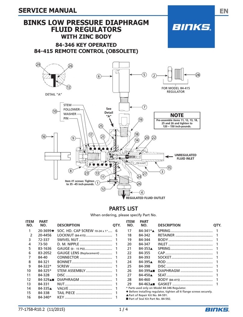
PART LIST
For the arrangement of the parts, refer the exploded view at the end of the manual.
Rep. Order number Description Qty
1 HGB-404-1 Adjusting key 1
2 HGB-28 Cover 1
3A
3B S-1309-H
S-1330-H For HGB-509-5-R38 or 609-x-R38, Screw M5 * 16
For HGB-510-R1, R2 & R4, or (CO), Screw M5 * 25 6
4 HGB-408-H Adjusting screw assembly 1
5 HGB-7 Adjusting nut 1
6 HGB-403-H Stem kit 1
7HGB-13-H
HGB-42
HGB-43
Spring for diaphragm for HGB-509-5-R38 or HGB-609-5-R38.
Spring for diaphragm for HGB-609-1.2-R38.
Spring for diaphragm for HGB-609-9-R38. 1
8A
8B S-24383
SSP-6462 Connector M5 for Rilsan tube. 2.7 *4 mm
Elbow connector M5 for rilsan tube 2.7*4 mm 1
1
9 HGB-54 Cover for HGB-510 1
10 HGB-55-K Air diaphragm HGB-510 1
11R1
11R2
11R4
HGB-67
HGB-56
HGB-63
Disc for HGB-510-R1 or R1CO
Disc for HGB-510-R2 or R2CO
Disc for HGB-510-R4 or R4CO 1
12
12b HGB-68
HGB-64 Intermediary washer for R2 & R4
Intermediary washer for R4 1
13 HGB-57-1 Intermediary body 1
14m
14R HGB-422
HGB-424 Fluid diaphragm assy. for HGB-509, 609.
Fluid diaphragm assy. for HGB-510-R1/R2/R4 or 1CO, 2CO, 4CO 1
15 Regulator body 1
16 HGB-426-CO
HGB-426
HGB-426-R38
Kit of Fluid inlet & ball valve with spring (3/8’’BSP/NPS Male).
Kit of Fluid inlet & ball valve with spring (1/4’’BSP Female).
Kit of Fluid inlet & ball valve with spring (3/8’’BSP/NPS Female). 1
17 S-28216 Gasket “D”shape 1
18 HGB-62 Teflon gasket 1 / 2
19 HGB-61
HGB-81
HGB-82
Fluid outlet connector for HGB-510-Rx, 1/4’’Female
Fluid outlet connector for HGB-509-5-R38, 3/8’’universal Male
Fluid outlet connector for HGB-609-xx-R38, 1/4’’BSP Male 1
20 HGB-49 Fluid outlet insert connector for HGB-510-Rx-CO 1
21 HC-1000 Fluid outlet swivel connector for HGB-510-Rx-CO 1
22 HGB-60
HGB-59
HGB-80
Fluid inlet connector Female 1/4’’BSP for HGB-510-Rx
Fluid inlet connector Male 3/8’’universal for HGB-510-Rx-CO
Fluid inlet connector Female 3/8’’BSP for HGB-509/609-R38 1

SB-6-HGB-H 14/40

SB-6-HGB-H 15/40
PREVENTIVE MAINTENANCE
Periodic cleaning of regulator with a solvent compatible with the material being used is
recommended. To clean material from the regulated material line and the regulator, these steps
should be followed :
1. Relieve supply line pressure.
2. Put the regulator in flushing position (See “Operation”). This holds the valve off its seat.
3. Blow material back through the regulated line by introducing air pressure into the line down
stream from the regulator. With spray gun attached this can be done by loosening air cap
ring on gun, holding a rag over air cap and pulling gun trigger. This forces air in a reverse
path through spray gun and air forces material back through regulated material line.
4. Unscrew the fluid inlet connector remove the spring and the ball valve. Clean all the parts
and the gasket inside the valve body. If the gasket is damaged replace it. Please follow the
instruction described on page 6. If the gasket is ok put thread locking compound (loctite
222) on the connector thread and tighten to a maximum torque of 6.4Nm.
Periodically clean exterior of regulator with solvent soaked rag.
REPLACEMENT OF PARTS
Note : Relieve the line pressure before servicing for pneumatic model (HGB-510). For manual
model HGB-509 & 609, Relieve spring forces by unscrewing the adjusting screw rep 4 at the
maximum (FIG A).
TO REPLACE DIAPHRAGM
1. Remove the 6 hex. head cap screws.
2. The diaphragm is sold complete with its washer and its fluid flow plastic deflector. These
parts could be not separated, if diaphragm or the deflector is damaged replace it.
3. Install the new diaphragm kit into the regulator body.
4. Put the cover on the regulator and screw the 6 screws at 7.5 to 8 mN.
5. For the pneumatic model HGB510, reassemble all the parts in the right order and position. It’s
recommended before to set the regulator that the two diaphragms work about 10 time so to be
in full condition, this operation could be done in using the connector Rep 8 and pressurize the
flushing cavity at 4 bar.
TO SERVICE VALVE ASSEMBLY
“Perlast D shape”seat and Ball valve.
1. Unscrew the fluid inlet valve and connector rep 16 from the regulator body.
2. Clean and check the valve, if the parts are damaged, replace the parts in using the valve kit.
3. Fit the washer in the right position small dimension in front of the “D”gasket, Screw the
valve body on the regulator body with a sealing compound “loctite 270”on the third thread
and tight at maximum torque 12Nm, Do not exceed this torque, over torque will damaged
the regulator body.
4. Wait a few minutes for the loctite to dry and fit the ball valve and the spring
5. Clean the thread on the fluid inlet connector, use a thread locking compound like Loctite 222.
6. Apply a maximum torque 6.4Nm.

SB-6-HGB-H 16/40
SERVICE CHECKS
CONDITION CAUSES REMEDES
Improper seating of valve stem
on seat. Be sure that seat and ball valve
are not damaged, worm or
dirty.
Regulated pressure creep.
Diaphragm leaking. Replace.
Restriction in main material line
or at valve seat inlet. Clear l'obstructionRegulated pressure drop.
Diaphragm damaged. Replace.
Loose cap screws. Screw the 6 screws at a torque
8 mN.
Fluid leakage from under
bonnet.
Diaphragm damaged. Replace.
ACCESSORIES
1/ MA-25, GA-333, GA-288 : Manometer 2.5b, 6b or 10bar.
2/ S-3008 : Stainless steel adapter 1/4’’BSP female / female
3/ S-3007 : Stainless steel riser tube 1/4’’BSP –male/male
4/ S-3006 : Tee in stainless steel 1/4’’BSP –Female
5/ HGB-66 : Stainless steel reducer 1/4’’x 3/8 ‘’BSP male/male (no retention)
S-3009 : Stainless steel coupling 1/4’’BSP Male/Male
6/ HGB-65 : Regulator support in steel, Regulator can be fitted above the support by using 2
screw standard (Not supplied) in Stainless steel M5*10 added 2 washers

Bedienungsanleitung
SB-6-HGB-H 17/40
SICHERHEITSHINWEISE
Wichtig: Bitte lesen Sie vor der Inbetriebnahme der Anlage sorgfältig die nachstehenden Hinweise und
befolgen Sie die Anweisungen und Vorsichtsmaßnahmen. Der Arbeitgeber ist verpflichtet, seinem
Bedienungspersonal diese Hinweise zur Verfügung zu stellen.
BRAND- UND EXPLOSIONSSCHUTZ
Lösungs- und Schutzmittel können hoch entzündlich sein, insbesondere wenn sie versprüht werden.
* Die Arbeitsplätze müssen mit einer angemessenen Lüftungsvorrichtung ausgestattet sein, um die Bildung
von brennbaren Dämpfen zu verhindern.
* Rauchen oder offenes Feuer ist in den Sprühkabinen und den Vorbereitungsbereichen untersagt.
* In diesen Bereichen müssen Feuerlöscher bereitstehen.
Die Benutzer der Anlage sind zur Einhaltung der Konformitäten der nationalen Rechtsgebung und der
Versicherungsgesellschaften in Bezug auf die Lüftungseinrichtung, die Brandschutzmaßnahmen, die
Nutzung, Wartung und Instandhaltung der Arbeitsplätze verp.
FLUORCHLORKOHLENWASSERSTOFFE : Die Verwendung bestimmter Lösungsmittel (z.B. 111
Trichlorethan und Methylchlorid) kann durch chemische Reaktion eine Explosionsgefahr an verzinkten
Ausrüstungsteilen oder Ausrüstungsteilen aus Aluminium oder Zink auslösen. Bitte lesen Sie die
Anwendungshinweise für das auszubringende Produkt.
LÖSEMITTELHALTIGE PRODUKTE AUSSCHLIEßLICH MIT DEN FÜR DIESEN ZWECK
VORGESEHENEN UND VOM HERSTELLER EMPFOHLENEN AUSRÜSTUNGEN VERWENDEN.
STATISCHE ELEKTRIZITÄT. Sie entsteht durch die Zirkulation der flüssigen Medien in den
Leitungen. Ein elektrostatischer Funken, welcher in der Lage ist, bestimmte Lösungsmittel oder andere
Produkte zu entzünden, kann aufgrund einer hohen Durchflussmenge entstehen. Die Gehäuse und
Anschlüsse unserer Durchflussregler sind aus Edelstahl, was die Kontinuität der Erdung gewährleistet.
Kontrollieren Sie diese Erdungskontinuität. Die elektrische Verbindung zwischen dem Regler und der
Erdung muss mit einem Ohmmeter geprüft werden. Es wird ein Widerstand unter 106Ohm empfohlen.
SCHUTZAUSRÜSTUNGEN
Giftige Dämpfe: bestimmte Produkte können beim Ausbringen schädliche Auswirkungen haben, Reizungen
verursachen, oder der Grund für gesundheitliche Störungen sein. Die Etiketten und Sicherheits- oder
Gebrauchsinformationen des auszubringenden Produktes müssen aufmerksam durchgelesen werden. Bitte
beachten Sie die Empfehlungen und befragen Sie im Zweifelsfall den Produktlieferanten.
Der Einsatz von Schutzausrüstungen für die Atemwege wird für jeden Sprühvorgang empfohlen. Die Art
der Schutzausrüstung muss dem auszubringenden Produkt und seiner Konzentration entsprechen.
Während des Sprühvorgangs oder der Reinigung der Geräte muss ein Augenschutz getragen werden.
das Tragen von Handschuhen wird für das Ausbringen von bestimmten Lösungsmitteln oder Produkten
und die Reinigung der Geräte empfohlen.
SCHULUNG
Das Personal muss für die korrekte Bedienung und Wartung dieser Anlage angemessen geschult werden. Es
können Schulungslehrgänge zur Abdeckung sämtlicher Betriebsfunktionen erteilt werden. Für weitere
Informationen wenden Sie sich bitte an Ihren lokalen Fachhändler.
Die in diesem Dokument aufgeführten Anleitungen und Sicherheitsempfehlungen sowie die Etiketten des
auszubringenden Produktes müssen vor der Bedienung dieser Anlage aufmerksam durchgelesen und
verstanden werden.
UNSACHGEMÄßER GEBRAUCH
Der Anschluss oder der Gebrauch von Zubehör oder Ersatzteilen, für die keine Empfehlung gegeben wurde
oder die keine Originalteile sind, können gefährliche Situationen auslösen.
Vor der Zerlegung der Anlage zur Reinigung oder Wartung müssen die Druckluft- und Produktversorgung
geschlossen und von Restdruck befreit werden.
Die Entsorgung von gebrauchten Lösungsmitteln oder Produkten muss gemäß gesetzlicher Regelung
erfolgen. Das Verbrennen kann giftige Dämpfe erzeugen.
Die für den Einsatz dieser Anlage verwendeten Stoffe sind lösemittelbeständig, vorbehaltlich der
Empfehlungen in Bezug auf Kohlenwasserstoffe.
Die Regler oder Manometer dürfen nicht in einer Reinigungsmaschine für Sprühpistolen gereinigt werden
oder in Lösungsmittel getaucht werden, was die Manometer oder die Dichtungen beschädigen könnte.
Die in den Reinigungsmaschinen verwendeten Lösungsmittel müssen in regelmäßigen Abständen
kontrolliert werden, um zu gewährleisten, dass die Anlage nicht mit einem verseuchten Produkt gereinigt
wird. Bitte befolgen Sie die Empfehlungen des Maschinenherstellers.

SB-6-HGB-H 18/40
EINSATZBEREICH
Die Regler ermöglichen bei konstantem Druck die Produktversorgung von einer oder zwei
Pistolen per manueller Einstellung oder per Luftdrucksteuerung. Edelstahlkugel mit
Edelstahlrückholfeder und Perlast Sitz zum Ausbringen von Farben mit niedriger Viskosität und
Steuerung bei schwacher Hysterisis (Sollwert des Regeldrucks).
TECHNISCHE DATEN
Anschluss
Reg
Typ Artikelnr Entrée Sortie
Eintritts-
druck
min-max.bar
Austritts-
druck
max.bar
Max.
Ausbringmenge
L/min
Manometer-
skala
bar
HGB-509-5-R38 2 - 12,5 5 13 Keine
HGB-609-1.2-R38 1 - 8 1.2 8,3 0 - 2,5
HGB-609-5-R38 2 - 12,5 5 13 0 - 6
Manueller
Feder
HGB-609-9-R38
Innenge
winde
3/8 BSP
Außenge
winde
3/8 NPS
/BSP 3 - 15 9 13 0 - 10
HGB-510-R1 2 - 15 15 1,6 (Düse 1.1mm) Keine
HGB-510-R2 1 - 15 7 1,3 (Düse 1.1mm) Keine
HGB-510-R4
Innenge
winde
1/4 BSP
Innenge
winde
1/4 BSP 1 - 15 4 0,8 (Düse 1.1mm) Keine
HGB-510-R1-CO 2 - 15 15 1,6 (Düse 1.1mm) Keine
HGB-510-R2-CO 1 - 15 7 1,3 (Düse 1.1mm) Keine
Pneumatik
Regelung
HGB-510-R4-CO
Außenge
winde
3/8 NPS
/BSP
Innenge
winde
3/8 NPS 1 - 15 4 0,8 (Düse 1.1mm) Keine
Sämtliche Produktleitungen sind aus 303 Edelstahl, Membranen auf Teflonbasis, Hauben aus
vernickeltem Aluminium (manuell) oder eloxiert (gesteuert).
Die HGB-609 Regler sind am Austritt mit einem T-Stück, einem Aufsatz aus Edelstahl und einem
Manometer versehen. Die Dichtigkeit der Anschlüsse zwischen den Elementen muss gewährleistet
sein, um das Manometer zu schützen. Siehe Zubehör.
WICHTIG: Die Regler können für die meisten Anstriche und Deckanstriche verwendet werden.
Sie sind jedoch nicht für den Einsatz mit hochkorrosiven oder Schleifmitteln konzipiert. In diesem
Fall wird empfohlen, den Regler häufig und gründlich zu reinigen und/oder die Teile öfter
auszutauschen.
CE KONFORMITÄTSERKLÄRUNG
Wir, ITW Surfaces et Finitions, 163,171 Av. des Auréats BP 1453, 26014
Valence France, erklären als Hersteller des Reglers vom Produktmodell
HGB-510/509, dass das in diesem Dokument beschriebene Gerät den
folgenden Normen und Vorschriften entspricht:
EN 292-1 Teil 1 & 2: 1991, EN 1953: 1999; gemäß den
Schutzanforderungen der EG-Richtlinie 98/37/EC in Bezug auf die
Sicherheit von Maschinen.
Die Zubehörteile sind aufgrund der ATEX-Richtlinie 94/9/EC als
Komponenten eingestuft: Schutzgeräte und –systeme zur Verwendung in
explosionsfähigen Atmosphären, sie entsprechen den Artikeln dieser
Richtlinie, Anhang II 2 G
Direktor: Claude FERRET
ITW Surfaces & Finition behält sich das Recht auf unangekündigte
Änderungen der technischen Merkmale der Anlage vor.

SB-6-HGB-H 19/40
INSTALLATION
Die HGB Regler müssen möglichst horizontal installiert werden, um zu verhindern, dass sich
das darin enthaltene Medium ablagert. Das Aufsatzrohr und das Manometer müssen vertikal
installiert werden. Auf diese Weise wird das Manometer durch die im Aufsatzrohr verbliebene
Luft geschützt. Eventuelle Lecks an den Rohrverbindungen oder am Manometer müssen
beseitigt werden, da der Druckanzeiger sonst beschädigt wird.
Die Versorgungsleitungen werden von einer Pumpe oder einem unter Druck stehenden Tank
ausgehend an das am unteren Ende des Reglers befindlichen Eintrittsstutzen mit 1/4’’BSP oder
mit 3/8’’BSP/NPS Universal Anschluss. Siehe Seite 18, Anschlußgröße ist modelabhängig.
Die Versorgungsleitungen zu einer oder zwei Pistolen werden seitlich an den 1/4’’BSP
Austrittsanschluss oder den 3/8’’BSP Anschluss. Siehe Seite 18, Anschlußgröße ist
modelabhängig.
Der Regler muss geerdet sein, um elektrostatische Ladungen zu beseitigen, die aufgrund des
Medien- oder Luftdurchflusses entstehen können. Die Erdung erfolgt über eine der Schrauben
Pos. 3A oder 3B. Die Erdungskontinuität wird mit einem Ohmmeter geprüft, es wird ein
Widerstandswert unter 106Ohm empfohlen
Versichern Sie sich bei der Inbetriebnahme, dass sich keine Luftblase unter der Membrane des
Reglers befindet, was die Regulierungspräzision bei geringem Durchfluss beeinflussen könnte.
ACHTUNG
Bei der ersten Inbetriebnahme einer Anlage wird empfohlen, die Speiseleitung nicht durch den Regler
laufen zu lassen, um diesen nicht zu verunreinigen und damit sich keine Verschmutzungen oder Späne
auf dem Ventilsitz des Reglers ablagern. Es wird die VERWENDUNG EINES FILTERS empfohlen.
BEDIENUNG
Manueller Regler
Das Einstellen des Produktdrucks erfolgt mit Hilfe des
Spezialschlüssels (Abb. A). Werkzeugvierkant des
Schlüssels in die Öffnung über dem Regler einführen.
Nach rechts drehen, um den Druck zu erhöhen, nach links
drehen um den Druck zu verringern.
Position Spülen bei maximaler Öffnung; den
zylindrischen Teil des Schlüssels einführen und bis zum
Anschlag festziehen um die auf dem Membranträger
gelagerte Stange nach unten zu schieben und den Regler
auf diese Weise vollständig für eine optimale Spülung zu
öffnen.
Pneumatischer Regler
Modelle HGB-510-R1, R2 oder R4.
Der Produkt-Regeldruck wird mit Hilfe des von einem
Nebenregler kommenden Steuerdrucks angepasst. Zu
diesem Zweck wird ein Luftrohr an den Anschluss auf
der Abdeckung des Reglers montiert. Um eine optimale
Regulierung zu erzielen wird empfohlen, den
Druckluftregler so nahe wie möglich am Produktregler
zu montieren. Erlaubt die Anlage dies nicht,
gewährleistet die Erzeugung eines minimalen
Luftaustritts des am Eintritt des Steuerungsanschlusses
befindlichen Rilsan-Rohrs eine maximale Reaktivität
des Druckluftreglers. Position Spülen bei maximaler Öffnung, Anschlussversorgung mit
Druckluft zur Spülsteuerung bei vollständiger Öffnung.
Achtung: DER SPÜLSTEUERDRUCK MUSS UM MAX. 1 BAR HÖHER IM
VERHÄLTNIS ZUM VERSORGUNGSDRUCK DES LÖSUNGSMITTELS SEIN.
Fig A
Fig B

SB-6-HGB-H 20/40
Nota : Nach durchgeführter Spülung muss der Kreislauf entleert werden, um zur
Anfangseinstellung zurückzukehren. Die Zwischenkammer kann auf sichere Weise für den Fall
eines Lecks der Membrane genutzt werden, um das Aufsteigen des Produkts in den
Druckluftsteuerungskreislauf zu verhindern.
Zur Unterscheidung der Reglermodelle zwischen R1, R2 und R4 befindet sich ein Pfeil auf der
Abdeckung entweder gegenüber des Eintrittsanschlusses der Spülsteuerung bei Modell R1, oder
gegenüber der Angabe 1/ 4 oder 1/ 2 auf dem Gehäuse des Zwischenreglers bei den beiden
anderen Modellen. Bei der Wartung des Reglers ist es notwendig beim Wiederzusammenbau auf
die Position des Pfeils im Verhältnis zum Zwischengehäuse zu achten.
ERSATZTEILLISTE
Anordnung der Teile siehe Berstschema.
Reg. Artikelnr Artikelbezeichnung Menge
1 HGB-404-1 Stellschlüssel 1
2 HGB-28 Reglerhaube 1
3A
3B S-1309-H
S-1330-H Für HGB-509-5-R38 und HGB-609-x-R38, Schraube M5 * 16
Für HGB-510-R1, R2 und R4, oder (CO), Schraube M5 * 25 6
4 HGB-408-H Stellschraube 1
5 HGB-7 Stellmutter 1
6 HGB-403-H Stab 1
7HGB-13-H
HGB-42
HGB-43
Membranenfeder für HGB-509-5-R38 und HGB-609-5-R38.
Membranenfeder für HGB-609-1.2-R38.
Membranenfeder für HGB-609-9-R38. 1
8A
8B S-24383
SSP-6462 Gerades Anschlussstück M5 für Rilsan-Rohr Durchm. 2.7 *4 mm
Winkel-Anschlussstück M5 für Rilsan-Rohr Durchm. 2.7*4 mm 1
1
9 HGB-54 Abdeckung für HGB-510 1
10 HGB-55-K Luftmembrane für HGB-510 1
11R1
11R2
11R4
HGB-67
HGB-56
HGB-63
Mitlaufscheibe für HGB-510-R1/1CO
Mitlaufscheibe für HGB-510-R2/2CO
Mitlaufscheibe für HGB-510-R4/4CO 1
12
12b HGB-68
HGB-64 Zwischenscheibe für Regler R2, R4
Zwischenscheibe für Regler R4 1
13 HGB-57-1 Zwischengehäuse 1
14m
14R HGB-422
HGB-424 Produktmembrane für HGB-509, 609.
Produktmembrane für HGB-510-R1/2/4 oder 1CO/2CO/4CO. 1
15 Reglergehäuse 1
16 HGB-426-CO
HGB-426
HGB-426-R38
Satz Federkugelventil mit 3/8’’BSP/NPS Eintrittsanschluss.
Satz Federkugelventil mit 1/4’’BSP Eintrittsanschluss mit Innengewinde.
Satz Federkugelventil mit 3/8’’BSP/NPS Eintrittsanschluss. 1
17 S-28216 Dichtung 1
18 HGB-62 Teflon-Dichtungen 1 / 2
19 HGB-61
HGB-81
HGB-82
Materialausgang für HGB-510-Rx, 1/4’’BSP Eintrittsanschluss
Materialausgang für HGB-509-5-R38, 3/8’’universal Außengewinde
Materialausgang für HGB-609-xx-R38, 1/4’’BSP Außengewinde 1
20 HGB-49 Einsatz für Materialausgang für HGB-510-Rx-CO 1
21 HC-1000 Materialausgang mit Drehgelenk für HGB-510-Rx-CO 1
22 HGB-60
HGB-59
HGB-80
Materialeingang Innengewinde 1/4’’BSP für HGB-510-Rx
Materialeingang Außengewinde 3/8’’universal für HGB-510-Rx-CO
Materialeingang Innengewinde 3/8’’BSP für HGB-509/609-R38 1
This manual suits for next models
12
Table of contents
Languages:
Other Binks Controllers manuals
Popular Controllers manuals by other brands

Hewalex
Hewalex OPTI-TEMP Installation and maintenance guide

Emerson
Emerson Dixell XR20CH Installing and operating instructions

Emerson
Emerson dixell WING XW260K Installing and operating instructions

Aqua Environment Inc
Aqua Environment Inc 211 Owner's operation and maintenance manual

Sony
Sony HomeShare RMN-U1 Quick setup guide

PRECISION DIGITAL
PRECISION DIGITAL ProVu PD6310 instruction manual