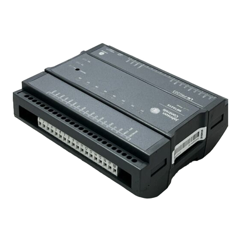
Johnson Controls DS-3153 User manual
Other Johnson Controls Controllers manuals
Johnson Controls
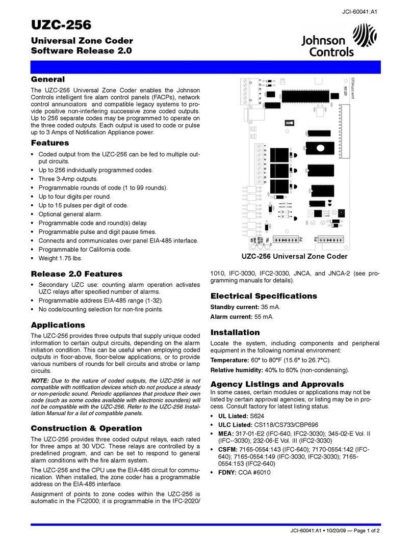
Johnson Controls UZC-256 User manual
Johnson Controls
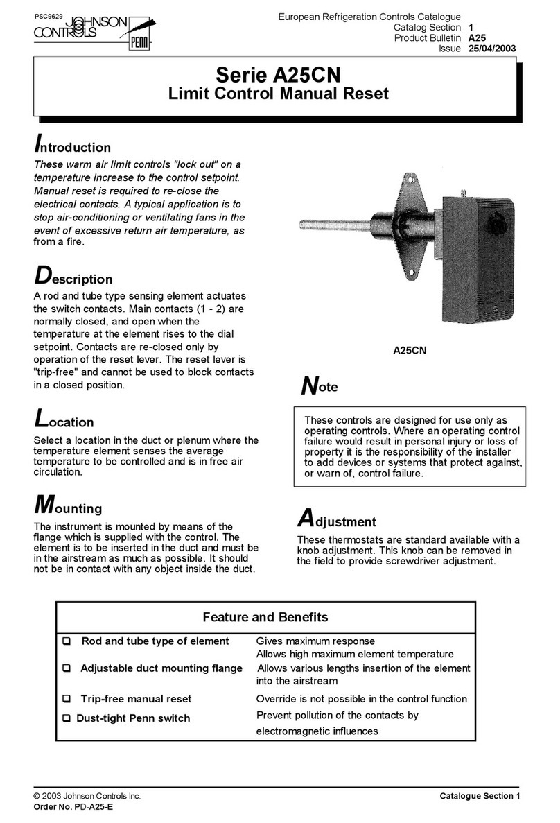
Johnson Controls A25CN Series Guide
Johnson Controls
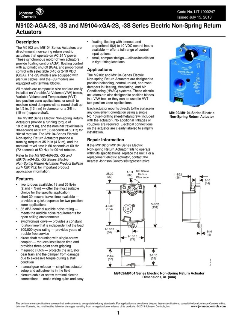
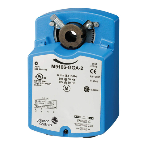
Johnson Controls M9106 Series User manual
Johnson Controls
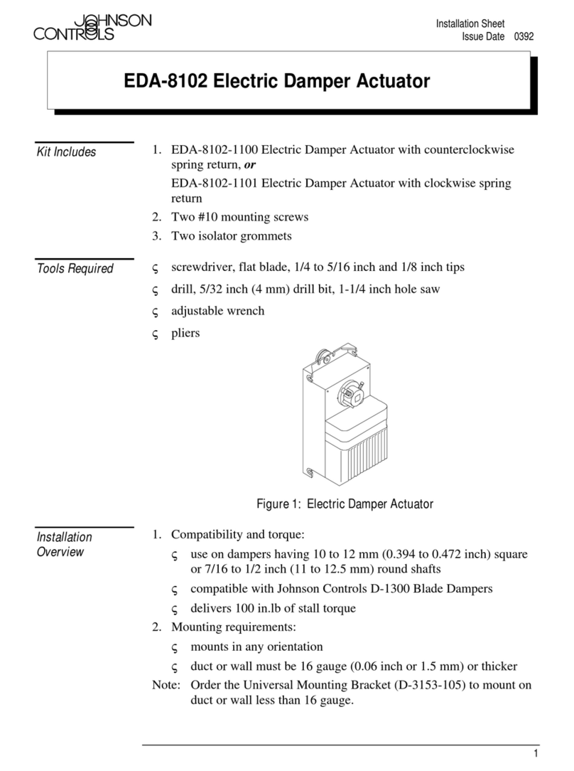
Johnson Controls EDA-8102 Assembly instructions
Johnson Controls
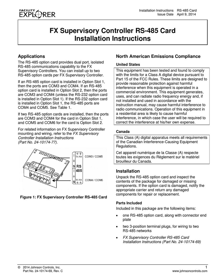
Johnson Controls FX Supervisory Controller RS-485 Card User manual
Johnson Controls
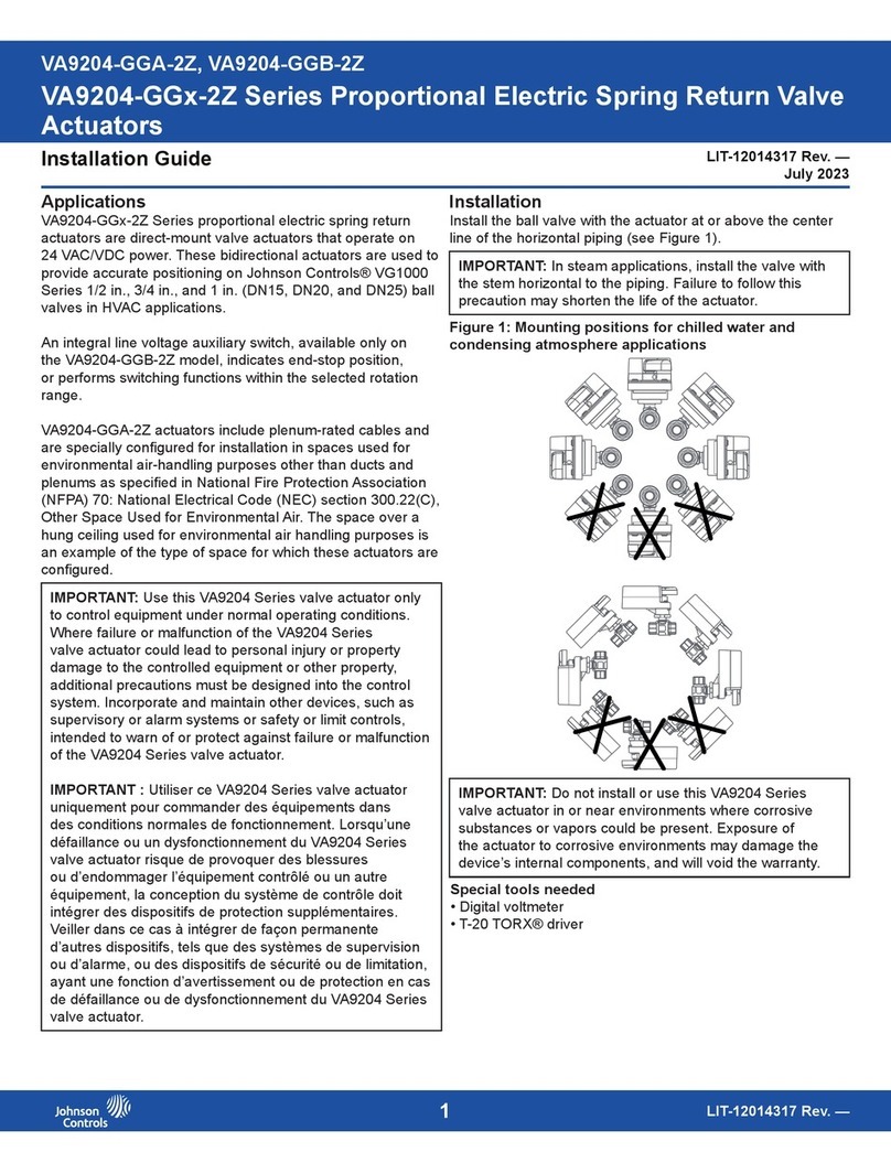
Johnson Controls VA9204-GG-2Z Series User manual
Johnson Controls
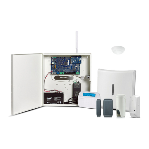
Johnson Controls HS3032 User manual
Johnson Controls
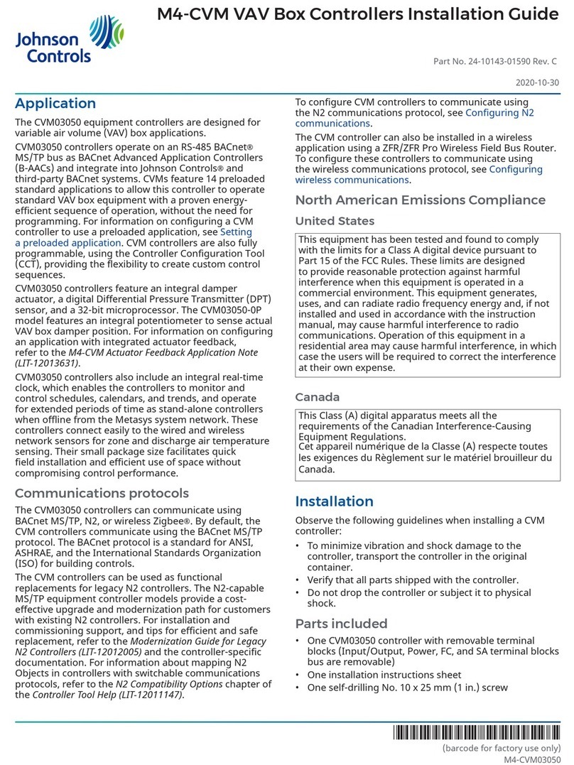
Johnson Controls CVM03050 User manual
Johnson Controls
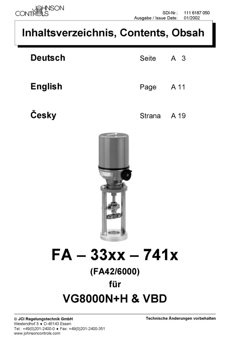
Johnson Controls FA-33-741 Series User manual
Johnson Controls
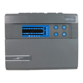
Johnson Controls Metasys DX-9100 Service manual
Johnson Controls
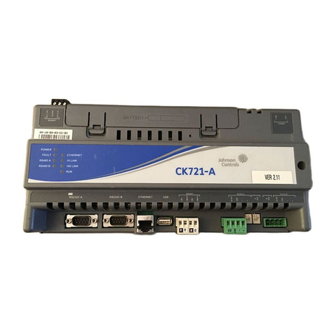
Johnson Controls CK721-A Assembly instructions
Johnson Controls
Johnson Controls FMS-2000C User manual

Johnson Controls
Johnson Controls F4-CV Series User manual
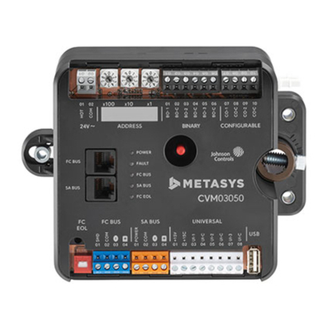
Johnson Controls
Johnson Controls M4-CV Series User manual
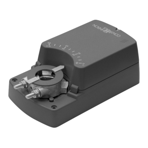
Johnson Controls
Johnson Controls M9116-GG-1N4 Series User manual
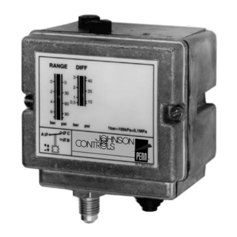
Johnson Controls
Johnson Controls P77 Series User manual
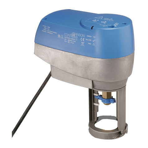
Johnson Controls
Johnson Controls VA7800 Series User manual
Johnson Controls
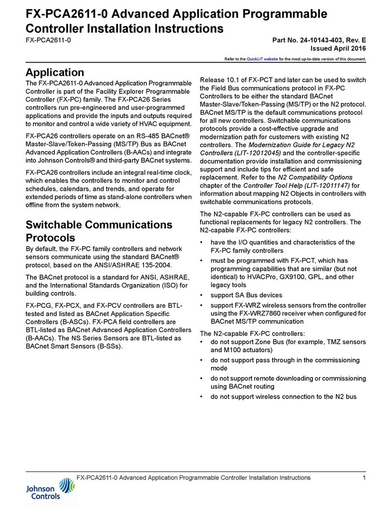
Johnson Controls FX-PCA2611-0 User manual
Johnson Controls
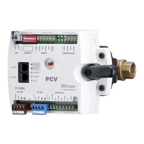
Johnson Controls FX-PCV1656 User manual
Johnson Controls
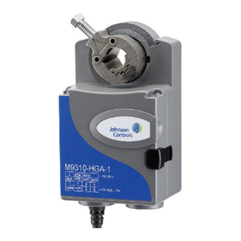
Johnson Controls M9308-A Z Series User manual
Popular Controllers manuals by other brands

Digiplex
Digiplex DGP-848 Programming guide

YASKAWA
YASKAWA SGM series user manual

Sinope
Sinope Calypso RM3500ZB installation guide

Isimet
Isimet DLA Series Style 2 Installation, Operations, Start-up and Maintenance Instructions

LSIS
LSIS sv-ip5a user manual

Airflow
Airflow Uno hab Installation and operating instructions
