TeeJet 845-AB User manual

REFERENCE GUIDE
1
98-01611-EN R0
POWER
Power On the Console
To power on the console:
1. Press and release the PROGRAMME button.
The console will initially display the software version at the top of
the screen and the serial number of the console at the bottom of the
screen. After approximately 3 seconds, the console will enter the
work screen.
Power O the Console
To power off the console:
1. While pressing and holding the MINUS button, press and
release the PROGRAMME button.
2. Release the MINUS button.
The console will save new information (area and volume counters)
to memory before it powers down. Pressing any key during the
power off count down will cancel the shut off function.
Automatic Shutdown
With the Master Switch in the “OFF” position, the console will
automatically shut down after 10 minutes of no inputs (or at the time
specied in the Automatic Shutdown Time setting in the OEM Setup
Mode).
APPLICATION MODE
The 845-AB gives the possibility of working in two different ways
to t the application. Therefore, the console should be set up and
consequent programming and working features will be dependant
of the chosen mode.
Airblast Mode
This mode is designed to work with Airblast sprayers, mostly
spraying on two sides (left and right) with the possibility to switch
on or off sections in the height. The working width is dened by
the distance between two rows of trees. This mode is called AB
(airblast).
Figure 1: Airblast (AB) principle
-2-L
-1-L
-2-R
-1-R
Working Width
High Clearance / Vineyard Mode
This mode is designed to work with vineyard sprayers that are
spraying horizontally. Several rows are covered and sections can
be switched on or off to adapt the working width. Each section
covers a number of faces. The working width is dened by the
number of faces and the row width.
One or more nozzles can be spraying each face. If all nozzles
spraying on a face are not equal, they should be considered
as a unique nozzle and the total ow has to be set up in the
conguration menu. But all faces have to be sprayed equally. This
mode is called HC (high clearance / vineyard).
Figure 2: High Clearance / Vineyard (HC) principle
Section 1 Section 2 Section 3
3 Faces 4 Faces 3 Faces
Face
Working Width
Row Width
845-AB SPRAYER
QUICK START GUIDE
298-01611-EN R0
REFERENCE GUIDE
Selecting a Mode
Application Mode is set by the Machine Type option on the OEM
Setup Menu. OEM setup mode contains the options that customize
the controller to the sprayer or sprayer components. These include
calibration steps and parameters that will never change once
programmed.
ADVISORY! OEM setup parameters (except Machine Type) should
not be changed unless advised by TeeJet Technologies or an
authorized dealer.
Enter OEM Setup Mode
To enter the OEM setup mode both the 845-AB console and Master
Switch must be off.
Press and hold the PLUS key and MINUS key
simultaneously while pressing the PROGRAMME key one time.
Wait for the display to show “Program menu OEM.”
While continuing to press and hold the PLUS key and
MINUS key simultaneously, press the PROGRAMME key
3 times within 3 seconds to conrm menu access.
Exit OEM Setup Mode
To exit the OEM setup mode the Master Switch must be off.
Press and hold the PROGRAMME key for 3 seconds.
The inputs are stored, and the console will enter the Operation
Screen.
For information on all OEM options, see 845-AB OEM Reference
Guide 98-01612.
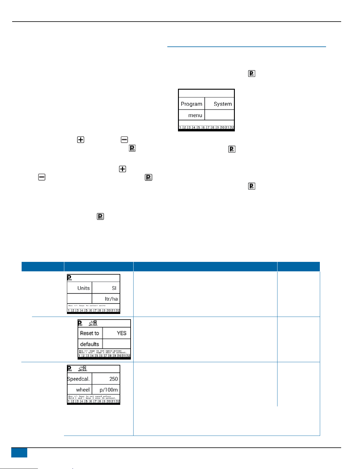
SYSTEM SETUP MODE
Enter the System Setup Mode
The Master Switch must be off.
Press and hold the PROGRAMME button until the Program
System Menu screen appears (approximately 3 seconds).
Advance to the Next Option
Press the PROGRAMME button to advance the system to the
next Program step. After the nal setup option is complete, the
console will return to the initial setup option.
Exit the System Setup Mode
Press and hold the PROGRAMME button for 3 seconds.
The inputs are stored, and the console will exit the setup mode.
Step Display Description Default
Units Select the units for operation.
Options include: US, SI.
US
Restore Defaults If the units of measurement are changed, default values for all
settings must be restored.
XYes – Units WILL be changed, and value WILL be reset.
XNo – units will NOT be changed, and value will NOT be
reset.
Yes
Speed Sensor
Calibration
Set number of Pulses per 300 feet/100 metres.
While it is difcult to give an accurate starting value for a wheel
speed sensor, radar (or simulated radar as with GPS speed)
sources usually having a starting value. Make sure the source is
set to “rad”.
100 metres
WTeeJet GPS Speed Sensor – default calibration number is 1300.
WMatrix Pro GS consoles – default calibration number is 914.
WMatrix 430 – default calibration number is 1000.

3
www.teejet.com
TEEJET TECHNOLOGIES
Step Display Description Default
Distance
Counter
The Distance Counter step is not a calibration step. It is a help
function that can be used to measure a distance in feet/metres
such as to conrm Automatic Speed Calibration. No value can
be entered here.
0 m
Pressure Sensor
Installed
Select if a pressure sensor is installed.
If a ow sensor is not installed, this step is automatically set to
“Yes” and cannot be changed.
Yes
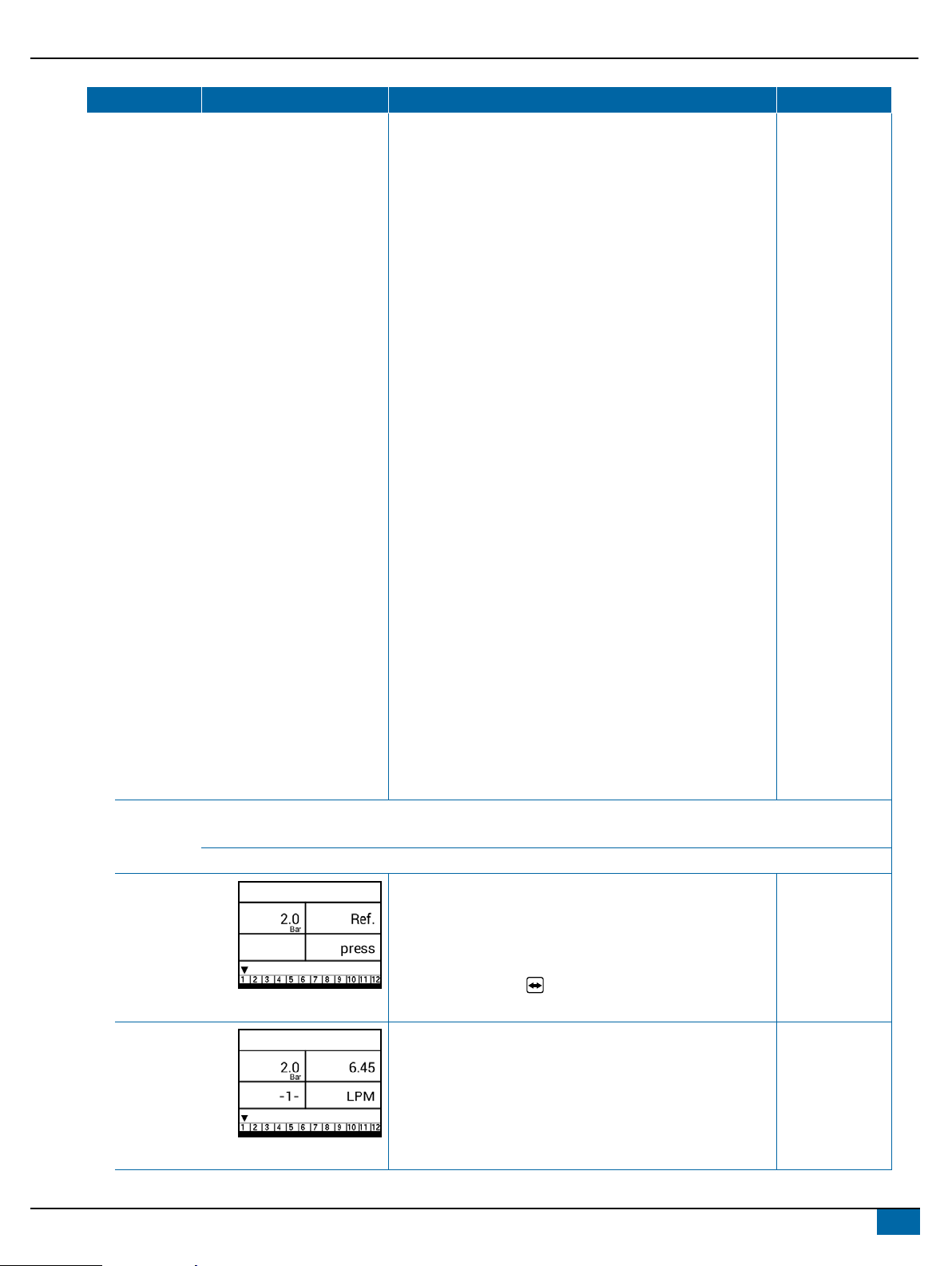
Pressure
Sensor->
Zero Pressure
Reference
This step is available if “Pressure Sensor Installed” is set to
“Yes”.
The Zero Pressure Reference is used to calibrate the zero
pressure setting of the pressure sensor installed on the system.
4.0 mA
Pressure
Sensor->
Maximum
Pressure Rating
This step is only available if “Pressure Sensor Installed” is set to
“Yes”.
The Maximum Pressure Rating is used to establish the
maximum rating of the pressure sensor in the system. This
number can be found stamped on the pressure sensor itself.
10.0 bar
Minimum
Pressure
Below the Minimum Pressure value, regulation is stopped,
except when using lane spraying (GLM or LKM).
0.6 bar
Flow Meter
Installed1
Select if a ow meter is installed. Yes
Flow Meter->
Flow Meter
Calibration
This step is only available if “Flow Meter Installed” is set to
“Yes”.
Sets the number of pulses per litre.
Pressing the AUTO/MAN button will switch between normal
value and decimal value (/10).
650 pulses per
litre
Most ow meters have a tag on the sensor cable which contains the proper ow
meter calibration number and units used, whether pulses per gallon, pulses per litre,
pulses per 10 gallons, etc.
XTeeJet 801 ow meter has a calibration number of 82.
XTeeJet 802 ow meter has a calibration number of 21.
1 If a pressure sensor is not installed this step is automatically set to “Yes” and cannot be changed. If no, skip the next 2 steps.

498-01611-EN R0
REFERENCE GUIDE
Step Display Description Default
Flow Meter->
Flow Sensor
Minimum Flow
Capacity
This step is only available if “Flow Meter Installed” is set to “Yes”
and the console is programmed for use with a pressure sensor.
Set the minimum ow capacity for the installed ow sensor.
Below the minimum ow capacity, regulation will switch to
pressure mode. When ow capacity once again reaches an
acceptable level for the ow meter to regulate, the console
automatically switches back to ow based regulation.
10.0 l/ min
Regulation Mode This step is only available when both a Flow Meter and a
Pressure Sensor are installed. This step is automatically set to
“Flow” and cannot be changed if lane spraying is selected (GLM
or LKM).
Selecting a regulation mode will determine which sensor is used
as the primary mode for regulation.
Flow
Number of
Sections
Select the number of sections. The number of sections must
match the physical number of sections on the sprayer.
NOTE: In HC mode, 1 to 13 sections can be selected. In AB
mode, 2 to 10 can be selected in steps of 2.
4 sections
Congure up to twelve ow presets. The ow presets are
represented by the numbers 1 through 12 at the bottom of
the display. The arrow symbol indicates which preset is being
congured.
Press the AUTO/MAN button to proceed to the next setting
for the selected ow preset.
1
5
www.teejet.com
TEEJET TECHNOLOGIES
Step Display Description Default
AB Mode – The ow rate for each section of the sprayer
must be input into the 845-AB console so that the necessary
adjustments can be made when boom sections are shut off. The
console is programmed to treat the left and right boom sections
as symmetrical; therefore the console treats the ow rate for
the lower left section (L1) identically to the ow rate of the lower
right section (R1). The ow rate entered for section 1 will serve
as reference ow for L1 and/or R1.
HC Mode – The ow rate for a single nozzle must be input
into the 845-AB console so that the necessary adjustments
can be made when boom sections are shut off. If several
different nozzles are mounted to spray on a face, they should
be considered as ONE nozzle and the total ow should be
programmed.
NOTE: In AB mode, the reference flow is the total flow at
reference pressure of all nozzles on the given section
number on one side of the sprayer. The console is
programmed to treat the left and right boom sections as
symmetrical. Therefore, the console treats the flow rate
for the lower left section (L1) identically to the flow rate
of the lower right section (R1). The flow rate entered
for section 1 will serve as reference flow for L1 and/
or R1. The flow rate entered for section 2 will serve as
reference flow for L2 and R2 and so on.
In HC mode there is only one setting per preset. The
reference flow in this case represents the flow for one
single nozzle at the reference pressure. If several
different nozzles are mounted to spray on each face,
they should be considered as ONE nozzle and the total
flow should be programmed. All faces on the sprayer
must have the same nozzle configuration.
Flow Presets
Conguration
Flow Presets
Conguration->
Reference
Pressure
Conguration
This step is only available if a “Flow Presets Conguration” is
active.
The display will show the reference pressure for the current ow
preset selected.
Press the AUTO/MAN button to proceed into the settings for
the selected ow preset.
2.0 bar
Flow Presets
Conguration->
Reference Flow
Conguration
This step is only available if a “Flow Presets Conguration” is
active.
Calculate (add) the ow rates at the referenced pressure from
all nozzles on the current preset section (left or right should be
the same).
Enter the total ow rate for the current ow preset selected.
6.45 l/min

698-01611-EN R0
REFERENCE GUIDE
Step Display Description Default
Density Establishes the weight per volume setting based on the type of
fertilizer being used.
Water = 1.00. The density value equals
Weight of the Solution ÷ Weight of Water.
1.00
Regulation Valve
Type
Instructs the console where the regulating valve is plumbed into
the system.
Options include: Throttle, Bypass and PWM
Bypass
Regulation
Speed Factor
Coarse
adjustment
Fine
adjustment
9.5
The rst digit sets the speed for the coarse adjustment in
relation to a large percentage outside of the target application
rate.
The second digit sets the speed for the ne tune adjustment
in relation to a small percentage close to the target application
rate.
Coarse: 9
Fine: 5
XIf plumbed in a bypass mode, the Regulation Speed Factor of 9.5 works very
well in most applications.
XIf plumbed in a throttling mode, start with a Regulation Speed Factor of 5.5
and adjust the number according to your application requirements. Low ow
situations will require a slower response time.
Section Valve
Type
The Section Valve Type distinguishes the type of On/Off boom
control valves installed on the machine.
2-way
Tank Size Sets the maximum tank size. 1000 litres
Minimum Tank
Level
Sets the tank level at which an alarm will trigger.
Setting this value to 0 will disable the tank alarm.
100 litres
Communication
Mode
The Communications step allows for the selection of the type of
communications (if any) used.
None
7
www.teejet.com
TEEJET TECHNOLOGIES
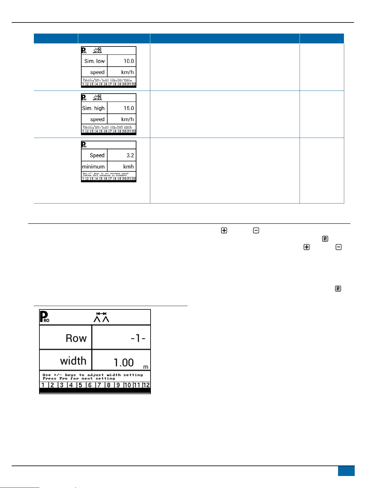
Step Display Description Default
Simulated
Ground Speed –
Low Speed
Set simulated low speed. 10.0 km/h
Simulated
Ground Speed –
High Speed
Set simulated high speed. 15.0 km/h
Minimum Speed Set the minimum speed at which the console automatically
shuts the boom sections off to eliminate an operator function
when slowing to stop or turn around. There will be no spraying
below this speed.
When the sprayer speed exceeds the established Auto Master
Off Speed, the boom sections turn back on.
Set this value to “0” to disable.
3.0 km/h
SWATH WIDTH
The 844-AB can be programmed with up to 6 swath widths. This
allows the operator to easily change from one swath to another
during application. (This is essential when spraying orchards that
have varying swath widths.)
To enter swath width presets mode, press and hold the GREEN
button for 3 seconds. The swath width setting screen for preset
number 1 will be displayed. The swath width is displayed on the
lower right of the console (measured in metres for SI [metric] units).
Figure 3: Entering swath width presets
Use the Plus and Minus keys to adjust the value for the rst
swath preset. Press the GREEN button or the Programme key
to advance to the next swath preset. Use the Plus and Minus
keys to adjust the swath value. Continue this process through the six
possible presets. If all six presets are not required, enter values only
for the necessary number of presets. All others should be set to “0”.
Values set to “0” will not be available for selection. Once the presets
have been entered, press the GREEN button or the Programme
key to return to the Operations mode.

898-01611-EN R0
REFERENCE GUIDE
Selecting a Swath Width Preset
Once the swath widths are programmed, select the swath width to
be used by pressing the GREEN button during Operations mode.
The console will display which swath preset is being used. If the
preset displayed is correct, press the Programme key to return to
Operations mode.
Figure 4: Swath width selection
Should a different swath preset be desired, press the GREEN button
again to advance to the next swath selection. Continue to press the
GREEN button until the appropriate swath preset is displayed. Press
the Programme key to select the preset and return to Operations
mode.
NOTE: Only presets that contain a width setting > 0 can be selected.
Pressing the green button will advance to the next preset
that has a width setting greater than 0.
APPLICATION SETUP MODE
The Application Setup Mode is used to set up application specic
parameters.
Enter the Application Setup Mode
The Master Switch must be off.
Press and release the PROGRAMME button once so the
Program User Menu screen appears. Press and release the
PROGRAMME button again within 3 seconds to enter the setting
options.
Advance to the Next Option
Press the PROGRAMME button to advance the system to the
next Program step. After the nal setup option is complete, the
console return to the initial setup option.
Exit the System Setup Mode
Press and hold the PROGRAMME button for 3 seconds.
The inputs are stored, and the console will exit the setup mode.
Activate Density Factor
At any time in Application Setup Mode, pressing the AUTO/MAN
button will toggle the density symbol (‘D’) on or off. When the density
symbol is on, the density value (set in System Setup mode) will be
used in the regulation algorithms. If the density symbol is off, the
density factor will not be used.

9
www.teejet.com
TEEJET TECHNOLOGIES
Step
AB Application Mode
Display
HC Application Mode
Display Description Defaults
Flow Preset
Selection
Sets which ow preset will be used. 1
Nozzles Per
Face
Sets the number of nozzles per face
(only available in HC Application
Mode).
3
Target
Application Rate
Sets the target application rate. AB 800 l/ha
HC 120 l/ha
Known Pressure
Value
The console will calculate the speed for
the selected pressure, Tip/Nozzle type
and target rate.
XIf the indicated speed is too high,
a set of smaller Tips/Nozzles is
required.
XIf the indicated speed is too low,
a set of larger Tips/Nozzles is
required.
2.0 bar
Known Speed
Calculation
The console will calculate what the
pressure must be to maintain the target
application rate at the entered speed.
No defaul
value
10 98-01611-EN R0
REFERENCE GUIDE
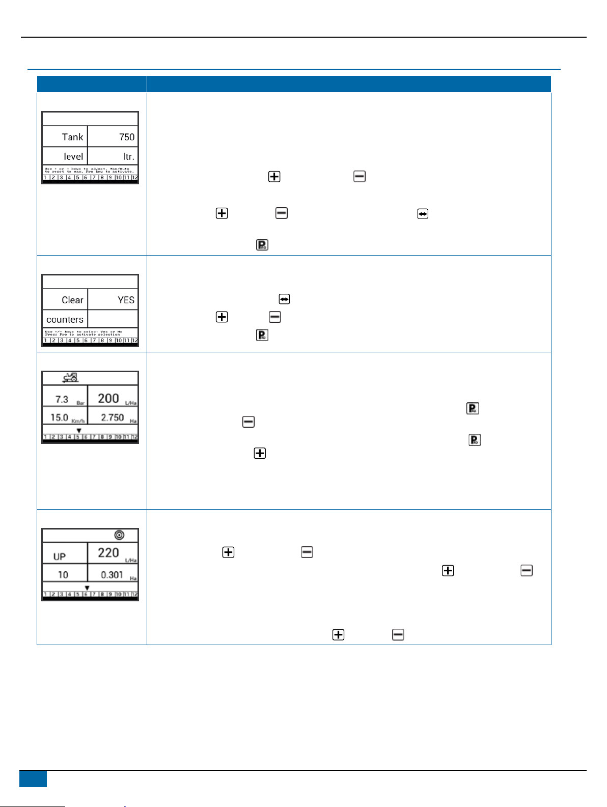
OPERATION FEATURES
Feature and Display Description
Tank Level Used to show and/or set the actual content level in the tank. This level will decrease by the amount being
sprayed. If the minimum tank level has been set to a value greater than zero and the actual level becomes
less than the minimum level, a tank alarm will be triggered. Setting minimum tank level to zero will disable
tank alarm function.
View Tank Level – Start from the work screen with the Master Switch “OFF”.
1. Press and release the PLUS button and MINUS button simultaneously.
Adjust Tank Level – Start from the work screen with the Master Switch “OFF”.
2. Use the PLUS and MINUS buttons. Or Press the MAN/AUTO button to reset tank level to
maximum.
3. Press the PROGRAMME button to conrm the selection and exit to normal work screen.
Clear Counters Used to reset the total area, total volume and total distance counters to zero.
Start from the work screen with the Master Switch “OFF”.
1. Press and hold the MAN/AUTO button for 3 seconds.
2. Use the PLUS or MINUS buttons to select “YES”.
3. Press the PROGRAMME button to conrm the selection and exit to normal work screen.
Simulated Speed Allows the verication of console functions and the sprayer without actually moving the sprayer.
Activate the Simulated Speed – While on the work screen without the machine in motion and the Master
Switch in the “On” position:
XActivate Low Simulated Speed – While pressing and holding the PROGRAMME button, press and
release the MINUS button.
XActivate High Simulated Speed – While pressing and holding the PROGRAMME button, press
and release the PLUS button.
Deactivate Simulated Speed – Once the sprayer begins moving and the console receives actual speed
pulses, simulated ground speed is deactivated. Simulated speed will also be deactivated if the console is
powered off.
Boost Function Used to increase or decrease the application rate by increments of 10%.
Increase/Decrease Target Application Rate
1. Press the PLUS button or MINUS button.
2. Within 3 seconds (while the boost activation period is active), use the PLUS button or MINUS
button, to increase or decrease the rate in steps of 10%.
After the activation period, the display will revert to normal, but if the rate has been changed, the target
symbol will stay visible and ashing.
Reset Target Application Rate – Press the PLUS and MINUS buttons simultaneously.

11
www.teejet.com
TEEJET TECHNOLOGIES
Feature and Display Description
Manual/Automatic
Regulation Mode
In manual mode, automatic rate regulation is stopped completely.
XPressing the PLUS button simply moves the regulating valve to increase the ow (or increase the
PWM duty cycle) as long as the button is pressed.
XPressing the MINUS button gives the opposite action.
The valve (or the PWM duty cycle) stays in the position it had when the PLUS or
MINUS button was released. The application rate value shown on the screen is the actual rate for the
given speed. Since automatic regulation is stopped, it will appear that the rate value changes when the
speed is changed.
ALARM SYSTEM
A number of sensor alarms have been included in the 845-AB software. The alarm system is only active with Master on. All audible alarm
signals can be cancelled by pressing any button. All alarms are reset when Master is switched off.
Alarm Name Display Description Audible Alarm Type
Rate Alarm Too high difference between target and
actual rate.
High Priority (3 short beeps, repeated
every second)
No Speed Alarm If speed is zero with master on, then no
speed alarm is triggered and spraying is
stopped.
Medium Priority (2 short beeps, repeated
every second)
No Flow Alarm If no ow pulses are received with master
on and ow meter installed, a no ow
alarm is triggered.
Medium Priority (2 short beeps, repeated
every second).
No Pressure
Alarm
If no pressure is measured with master
on and pressure sensor installed, a no
pressure alarm is triggered.
Medium Priority (2 short beeps, repeated
every second).
Low Pressure
Alarm
If pressure drops below minimum value
with master on, a low-pressure alarm is
triggered.
Medium Priority (2 short beeps, repeated
every second).

98-01611-EN A4LT R0 English-International
© TeeJet Technologies 2023
REFERENCE GUIDE
www.teejet.com
Alarm Name Display Description Audible Alarm Type
Low Speed
Alarm
If speed drops below minimum value with
master on, a low-speed alarm is triggered
and spraying is stopped.
Medium Priority (2 short beeps, repeated
every second).
Pressure
Difference
Warning
With ow based regulation, the controller
(if pressure sensor installed) will compare
the actual measured pressure with the
calculated pressure (based on ow and
nozzle type).
No audible alarm.
Flow Difference
Warning
With pressure based regulation, the
controller (if ow meter installed) will
compare the actual measured ow with
the calculated ow (based on pressure
and nozzle type).
No audible alarm.
Tank Level Alarm Current tank level drops below tank
minimum.
Low Priority (1 short beep, repeat every
second).
Table of contents


