Tegam 1316A User manual

1316A
Page 1 of 9
1316A-901, Rev. A
1316A RF HIGH-POWER CALORIMETER
INSTALLATION AND CALIBRATION
QUICK START GUIDE
1. EQUIPMENT LIST
The following equipment is required to complete the calibration:
•TEGAM 1316A, RF High-Power Calorimeter
•TEGAM 1300-912, Voltage/Current RF Adapter Assembly
•Preen AFV+ 31015, High Power Programmable AC Power Source
•Zimmer L64-BAS, Precision Power Analyzer
•Solid State Cooling Systems 1316-388, Thermorack Solid State Chiller (1 kW)
•Orion 1316-389, DC Inverter Chiller (12 kW)
•TEGAM HPC-CAL, Automated Calorimeter Calibration Software
WARNING: High voltage, current, and RF power are present in the
system at various times throughout this procedure. This procedure
should only be performed by qualified personnel sufficiently trained in
the safe operation of high voltage, current, and RF power systems.
Failure to follow these precautions may result in death or bodily injury,
or equipment damage.
2. SYSTEM INSTALLATION
Instrument Connections
WARNING: High voltage and current are present on the system. Install
proper safety equipment (e.g., fuses, breakers, etc.) as necessary
between the AC Power Source and Voltage/Current RF Adapter. Failure
to install adequate safety equipment may result in death or bodily
injury, or equipment damage.
1. Connect the Voltage/Current RF Adapter through an appropriately sized fuse or
breaker to the AC Power Source. See Figure 1 below.
Figure 1: Voltage/Current RF Adapter connections to the AC Power
Source.

1316A
Page 2 of 9
1316A-901, Rev. A
WARNING: Dangerous voltage, current, and RF power may be present
on the system. Users should install interlock devices as appropriate for
safe operation.
2. Connect interlocks (user-supplied) to the Calorimeter and system as
necessary.
3. Connect the Calorimeter and Power Analyzer ethernet ports to the network.
4. Connect the AC Power Source to the network using the ethernet port or the
RS-232 serial connection. Ethernet is preferred.
5. Connect the thermocouple from the Calorimeter to the 12 kW Chiller as shown
in Figure 2.
Figure 2: Thermocouple Wire Connection
WARNING: Comply with all local codes and regulations for installation
of all instrumentation. Follow guidelines in supplier manuals for
connections to AC Power Source and 12 kW Chiller. Failure to install
equipment properly may result in death or bodily injury, or equipment
damage.
6. Connect AC mains power to the Calorimeter, AC Power Source, 12 kW Chiller,
and Power Analyzer.The Power Analyzer and Calorimeter are powered from
separate 200-240 VAC outlets. The Calorimeter requires a 20A service.
Chiller Preparation
1. Fill the 1 kW Chiller coolant reservoir, located at the top of the system rack
cabinet (see Figure 3 below), 4 cm (15/8inches) above the return inlet with a
coolant mixture of 25% SR-1 antifreeze to 75% distilled water.

1316A
Page 3 of 9
1316A-901, Rev. A
Figure 3: 1 kW Chiller coolant reservoir
2. Power ON the Calorimeter and the 1 kW Chiller. Once the Calorimeter
completes the boot process:
a. On the Calorimeter front panel, press the SETUP softkey.
b. Navigate to Instrument using the arrow keys and press ENTER.
c. Navigate to PUMP and press ENTER.
d. Navigate to USE PUMP and press ENTER.
e. Press ENTER again to begin editing the parameter value.
f. Press the UP arrow key to change the parameter value to TRUE and
press ENTER.
3. Allow sufficient time for the coolant to circulate through the system before
proceeding to the next step.
NOTE: The coolant level may drop as coolant fills the
system hoses, Calorimeter, and 1 kW Chiller. If
necessary, add additional coolant mixture as necessary
to the 1 kW Chiller reservoir to bring the coolant level
back to 4 cm above the return inlet.
4. Power OFF the 1 kW Chiller.
5. Power OFF the Calorimeter and chiller
pump using the system rack power
switch.
6. Connect the supply and return hoses
between the 12 kW Chiller and the
system rack cabinet as shown in Figure 4.
7. Fill the 12 kW Chiller coolant reservoir
using about 50 liters (13.2 gallons) of a
25% SR-1 antifreeze and 75% distilled
water mixture.
8. Power ON the 12 kW Chiller.
9. On the 12 kW Chiller display, touch the PUMP ONLY icon and hold for 2-3
seconds to circulate coolant.
10. Allow sufficient time for the coolant to circulate through the system before
proceeding to the next step.
Figure 4:
Supply and
return hose
connections
1316A
Page 4 of 9
1316A-901, Rev. A
NOTE: If the coolant level drops and triggers a low coolant alarm, add additional coolant
mixture as necessary to the 12 kW Chiller reservoir until the alarm turns off. Clear the alarm
on the 12 kW Chiller display.
11. On the 12 kW Chiller display, touch the PUMP ONLY icon and hold for 2-3
seconds to stop flow circulation coolant.
12. Power OFF the 12 kW Chiller.
3. CALIBRATION
Preparation and Instrument Setup
1. Install the HPC-CAL calibration software on the system workstation.
2. Power ON the 12 kW Chiller.
3. On the 12 kW Chiller display, touch RUN and hold for 2-3 seconds.
4. Power ON the Calorimeter. Once the Calorimeter completes the boot process:
a. On the Calorimeter front panel, press the SETUP softkey.
b. Navigate to Instrument using the arrow keys and press ENTER.
c. Navigate to PUMP and press ENTER.
d. Press ENTER again to begin editing the parameter value.
e. Navigate to USE PUMP and press ENTER.
f. Press the UP arrow key to change the parameter value to TRUE and
press ENTER.
5. Verify that the green FLOW OK indicator is lit.
6. Power ON the 1 kW Chiller.
7. Connect cables CA-70-5 and CA-71-5 to the Power Analyzer as shown in Figure
5below.
Figure 5: CA-70-5 and CA-71-5 connections to Power Analyzer
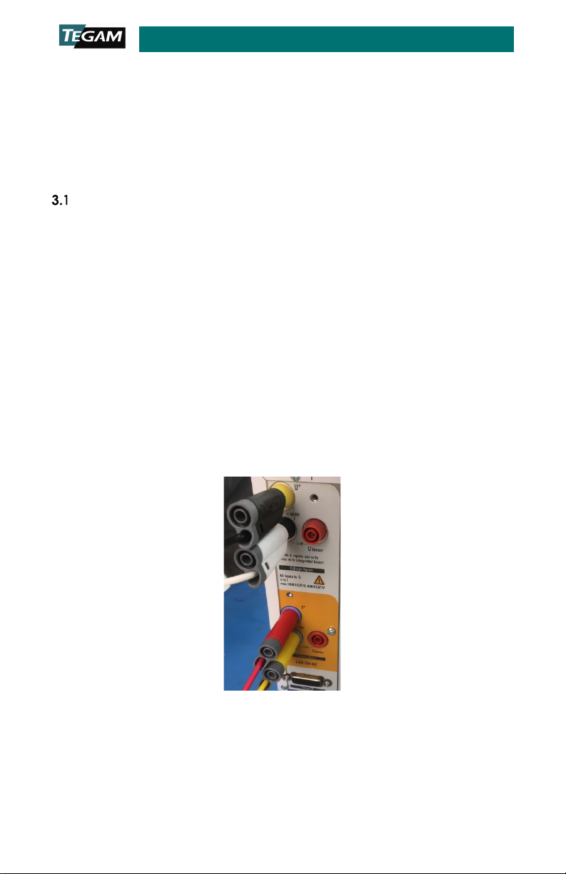
8. Connect cables CA-70-5 and CA-71-5 to the Voltage/Current RF Adapter as
shown in Figure 6 below.

1316A
Page 5 of 9
1316A-901, Rev. A
Figure 6: CA-70-5 and CA-71-5 connections to Voltage/Current RF
Adapter
9. Connect the Voltage/Current RF Adapter output HN RF connector to the
Calorimeter input HN RF connector.
10. Allow the system to stabilize for no less than two (2) hours before performing
the remaining steps of this procedure.
Calibration
1. Launch the HPC-CAL calibration software on the system workstation.
2. Click the Test Definition tab (see Figure 7 below).
3. Click the Read Test Definition button (see Figure 7).
Figure 7: HPC-CAL calibration software main window
4. In the Open File dialog box, select the Test Definition file titled HPC-
Cal_TestDefinitions_SNxxxx.XML.
5. Click Open to load the selected calibration test parameters into the HPC-CAL
calibration software as shown in Figure 8 below.

1316A
Page 6 of 9
1316A-901, Rev. A
Figure 8: HPC-CAL calibration software with Test Definitions file loaded
6. Click the Device Definitions tab (see Figure 9, Step 1 below).
7. Click the Configure Definition drop-down box (Figure 9, Step 2).
8. Click Calorimeter1316 in the drop-down box (Figure 9, Step 3).
9. Click the Network tab (Figure 9, Step 4).
10. Verify that the IP address displayed in the IP Addr textbox matches the
Calorimeter IP address (Figure 9, Step 5).
11. Click the Check button. If communication is properly configured, the
Calorimeter will respond with the instrument model number (Figure 9, Step 6).
12. Repeat Steps 7through 11 above for the AC Power Source and Power
Analyzer. In Step 9, click the tab that corresponds to the appropriate
communication protocol for the instrument being configured.
Figure 9: HPC-CAL calibration software Device Definitions tab
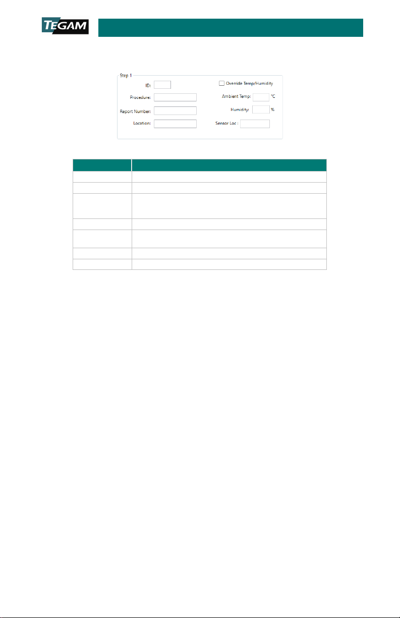
13. Complete the fields contained in the Step 1 group as shown in Figure 10.
TEGAM has defined the fields as described in Table 1 below, but the user may
1316A
Page 7 of 9
1316A-901, Rev. A
choose to input additional or different information in any field. Note that the
information will appear in various HPC-CAL calibration software output files.
Figure 10: Step 1 group fields
Field
Description
ID
Technician ID or initials.
Procedure
The calibration authority/procedure for the test.
Report
Number
The report number must be 10 characters and should be
unique. The date, including minutes (yymmddhhmm), is
recommended to ensure each report number is unique.
Location
Company or department name, or test station number.
Ambient
Temp Ambient temperature of the calibration environment.
Humidity
Ambient humidity in the calibration environment.
Sensor Loc
Physical location of the temperature/humidity sensor
Table 1: Step 1 group field definitions
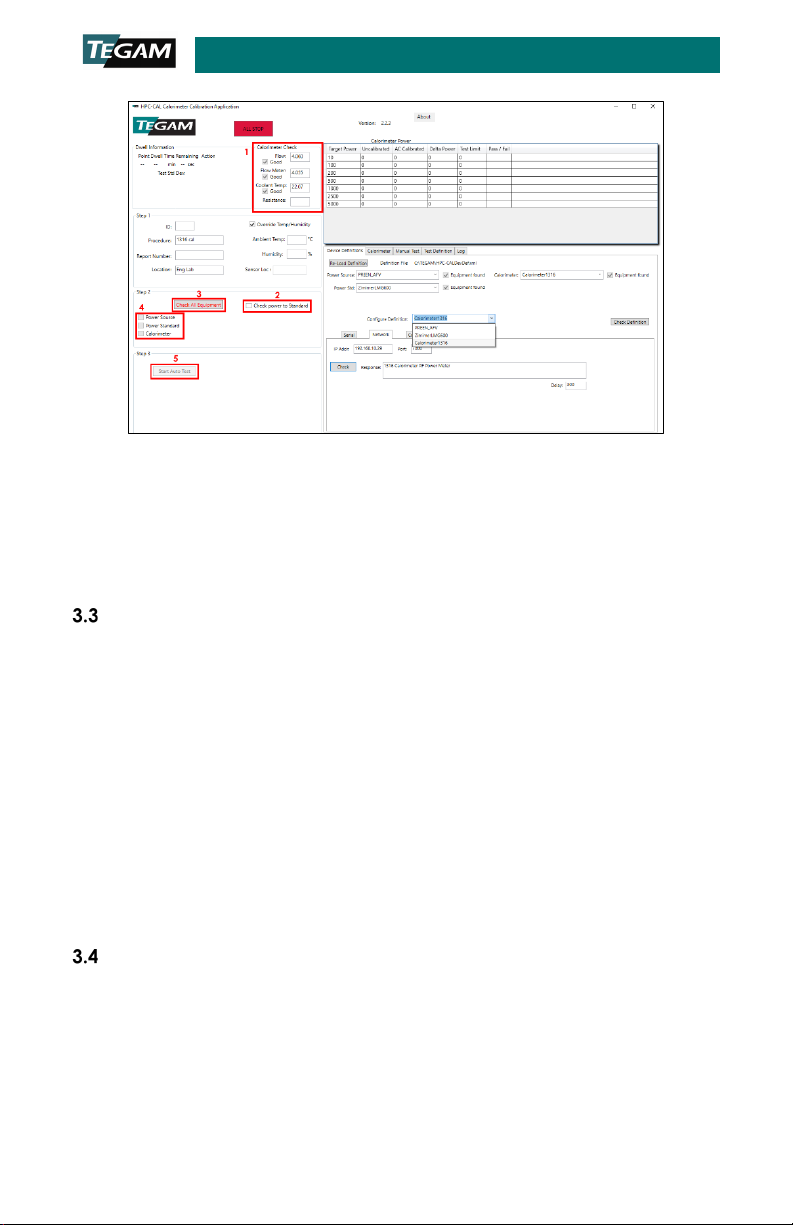
14. In the Calorimeter Check group, verify the Calorimeter Flow: and Flow
Meter:fields indicate 4.05 GPM ±0.03, and that Coolant Temp: indicates
22.1 °C ±0.4 (see Figure 11, Step 1 below).
15. (Optional) In the Step 2 group, click to select the Check power to standard
check box (Figure 11, Step 2).This setting instructs the HPC-CAL calibration
software to verify the connection between the Power Analyzer and AC Power
Source.
16. In the Step 2 group, click the Check All Equipment button (Figure 11, Step
3).
17. Wait approximately 60 seconds for the HPC-CAL calibration software to verify
communication with the connected instruments. Verify the Power Source,
Power Standard, and Calorimeter checkboxes are checked. The Check All
Equipment button text should be black (Figure 11, Step 4).
18. In the Step 3 group, click the Start Auto Test button (Figure 11, Step 5).
1316A
Page 8 of 9
1316A-901, Rev. A
Figure 11: HPC-CAL calibration software communication and test
parameter verification
19. In the dialog box, verify that the test power level, and Calorimeter serial and
model numbers are correct.
20. Click OK to dismiss the dialog box and begin the automated calibration.
21. The HPC-CAL calibration software will save a calibration data file in the current
user’s Documents directory at the completion of the test.
Data Analysis
NOTE: In rare cases, pop-ups may appear announcing that the measurement settling criteria
have not been met. If this happens, evaluate the warning and obtain Engineering approval
to continue test or abort test. Failure to meet settling criteria could be a sign of an equipment
malfunction, and each such failure should be analyzed. Repeated failure on one step may
indicate that the criteria is too tight, or the settling time is too short. In either of those cases,
the test definition can be changed consistent with quality requirements.
1. Navigate to the current user’s Documents directory
(%userprofile%\documents).
2. Locate and open the data file from the calibration completed in the previous
steps. The filename will be HPC-CALTest_yyyy_MM_dd_HH_mm_ss.log (yyyy
= four-digit year, MM = month, dd = day of month, HH = 24-hour clock hour,
mm = minutes, ss = seconds). The date/time portion of the file name
corresponds to the time the calibration finished.
3. If required for reporting or auditing purposes, copy the data file to an
appropriate location.
Alignment
1. In the HPC-CAL calibration software, click the Calorimeter tab (see Figure 12
below).
2. Click Create Cal. File and Save to create a new calibration file based on the
calibration data collected in Step 3.2. Calibration above (Figure 12).
3. In the dialog box, save the new calibration file in appropriate location. The file
name must be Calibration.ini as the Calorimeter will not read a calibration file
with any other name.

1316A
Page 9 of 9
1316A-901, Rev. A
NOTE: It is recommended to store the calibration file in its own directory, and name the
directory using the current date and other descriptive information as necessary. The directory
should contain no other calibration.ini files. Save the file as “Calibration.ini” and not as any
other name. The calorimeter will not use files with a different name.
4. Click Send Cal. File and Restart (Figure 12).
Figure 12: HPC-CAL calibration software Calorimeter alignment tab
5. In the dialog box, pick the calibration file saved in Step 3above.
6. Click OK to load the calibration file.
7. The Calorimeter will restart after loading the calibration file. The alignment is
complete when the Calorimeter restarts and completes the boot process.
Table of contents
Other Tegam Measuring Instrument manuals


Tegam
Tegam GEMINI 5540A User manual

Tegam
Tegam Advanced Energy GEMINI 5540A User manual

Tegam
Tegam R1L-BR1 User manual

Tegam
Tegam 1830A Troubleshooting guide

Tegam
Tegam 3525 User manual

Tegam
Tegam 710A User manual

Tegam
Tegam 730A User manual

Tegam
Tegam 710A User manual

Tegam
Tegam 720A User manual

Tegam
Tegam GEMINI 5541A User manual


