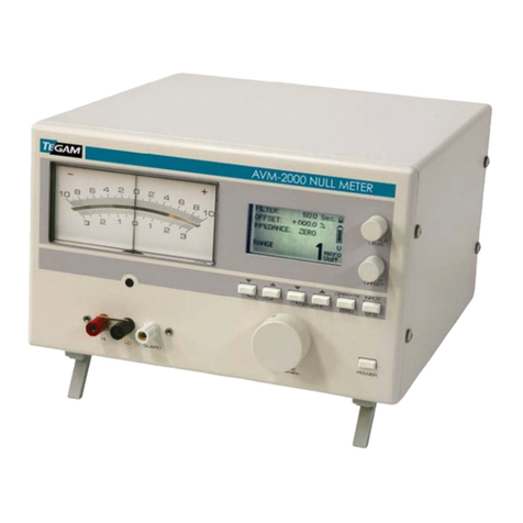
Tegam 1830A Troubleshooting guide

10 TEGAM WAY • GENEVA, OHIO 44041 440-466-6100 • FAX 440-466-6110 • www.tegam.com
TEGAM is a manufacturer of electronic test and measurement equipment for metrology,
calibration, and production test. We also provide repair, calibration, and other support services
for a wide variety of test and measurement equipment including RF power sensor calibration
systems, RF attenuation measurement systems, ratio transformers, arbitrary waveform
generators, micro-ohmmeters, LCR meters, handheld temperature calibrators, thermometers,
humidity and temperature control devices, and more.
TEGAM also repairs and calibrates test and measurement equipment formerly manufactured by
Electro-Scientific Industries (ESI), Gertsch, Keithley Instruments, Lucas Weinschel, and
Pragmatic Instruments. A complete list can be viewed on our Product Service Directory at
www.tegam.com
For more information about TEGAM and our products, please visit our website at
www.tegam.com: or contact one of our customer service representatives at sales@tegam.com
or 800-666-1010.
© Copyright TEGAM, Inc. 2010 - 2017
No part of this manual may be reproduced in any form or by any means (including electronic
storage and retrieval or translation into a foreign language) for any other purpose without the
prior written consent of TEGAM, Inc.
10 Tegam Way,
Geneva, Ohio 44041
Telephone: (440) 466-6100
Fax: (440) 466-6110

10 TEGAM WAY • GENEVA, OHIO 44041 440-466-6100 • FAX 440-466-6110 • www.tegam.com
Table of Contents
Section Page
I. Introduction
Purpose and Functions .............................................................. 1-1
Capabilities .............................................................................. 1-1
Specifications ........................................................................... 1-2
List of Items Furnished .............................................................. 1-4
List of Additional Items Required for Operation and Maintenance .... 1-4
Tools and Test Equipment.......................................................... 1-4
Preparation for Calibration or Repair Service ................................ 1-5
Warranty Information................................................................ 1-7
Contact Information .................................................................. 1-7
II. Preparation for Use and Installation
Unpacking and Inspection .......................................................... 2-1
Use in Proper Environment......................................................... 2-1
III. Principles of Operation
Understanding the 1830A Measurement Process ........................... 3-1
Theory of RF Power Measurements ............................................. 3-2
Principles of DC Substitution ............................................. 3-2
Power Measurements ....................................................... 3-2
Controlling Thermistor Temperature................................... 3-3
IV. Operating Instructions
Start-up Procedure ................................................................... 4-1
Standby Mode ................................................................. 4-1
Connecting the Proper Sensor ........................................... 4-2
1830A Front Panel Menus .......................................................... 4-3
1830A Menu Map .................................................................... 4-12
Normal Operation ................................................................... 4-13
RF Power Measurement Procedure ............................................ 4-13
Remote Operation................................................................... 4-15
Ethernet Interface Configuration…………………….……………….….4-17
1830A Commands .................................................................. 4-21
1830A Error/Status Reporting .................................................. 4-23
Sensor Calibration File Upload .................................................. 4-32
Heater Circuit Operation .......................................................... 4-34
Normal Shutdown Procedure .................................................... 4-35

10 TEGAM WAY • GENEVA, OHIO 44041 440-466-6100 • FAX 440-466-6110 • www.tegam.com
V. Maintenance and Servicing
1830A System Calibration and Diagnostics................................... 5-1
Calibration and Verification Equipment ........................................ 5-1
Calibration Environment ............................................................ 5-2
Disassembly of 1830A ............................................................... 5-2
Calibration and Diagnostic Process .............................................. 5-2
Troubleshooting........................................................................ 5-9
VI. Reprogramming
Reprogramming the 1830A ........................................................ 6-1
Memory Sanitization Procedure................................................... 6-2
VII. Preparation for Shipment
Returning Power Meter for Service .............................................. 7-1
Package Power Meter for Shipment ............................................. 7-1
VIII. Storage
Storage Requirement ................................................................ 8-1

10 TEGAM WAY • GENEVA, OHIO 44041 440-466-6100 • FAX 440-466-6110 • www.tegam.com
Safety Information & Precautions:
The following safety information applies to both operation and service personnel. Safety
precautions and warnings may be found throughout this instruction manual and the equipment.
These warnings may be in the form of a symbol or a written statement. Below is a summary of
these precautions.
Terms in This Manual:
CAUTION statements identify conditions or practices that could result in damage to the
equipment or other property.
WARNING statements identify conditions or practices that could result in personal injury or loss
of life.
Terms as Marked on Equipment:
CAUTION indicates a personal injury hazard not immediately accessible as one reads the
marking, or a hazard to property including the equipment itself.
DANGER indicates a personal injury hazard immediately accessible as one reads the marking.
Symbols:
As Marked in This Manual:
!
This symbol denotes where precautionary information may be found.
As Marked on Equipment:
!
CAUTION –Risk of Danger
DANGER –Risk of Electric Shock
Earth Ground Terminal
l
On
O
Off
Frame or Chassis Terminal
Earth Ground Terminal
Alternating Current

10 TEGAM WAY • GENEVA, OHIO 44041 440-466-6100 • FAX 440-466-6110 • www.tegam.com
1-1
Section I –Introduction
Purpose and Function
The 1830A power meter is designed for thermistor based RF power sensors which are universally
recognized as the most accurate means to measure and transfer RF power. The TEGAM Model
1830A is designed to replace the HP432 while further reducing uncertainties and accommodate a
wider variety of RF power sensors. It combines a modern DC substitution bridge with a 6.5 digit
measurement system to provide consistent normalized RF power readings manually or
automatically.
Key functions of the 1830A:
•Replaces the HP432 RF Power Meter
•Compatible with thermistor power sensors from: Agilent (HP), TEGAM,
Weinschel, Hughes, General Microwave, Millitech
•Supports 100 Ω and 200 Ω thermistors
•Integrates bridge balancer and power meter into one package
•Four digit calibration factor resolution
•Full remote programmability
•Heater control for ovenized sensors
Capabilities
There are many thermistor based RF power sensors available. The Model 1830A is designed to
bias either 100 Ω or 200 Ω mounts and has dual bridges for balancing both RF sense and
compensation thermistors such as contained in the Agilent 478A and 8478B. It also is works with
the Agilent 486A series of waveguide sensors and includes a heater circuit for all TEGAM and
Weinschel ovenized thermistor mounts.
Figure 1.1 - Model 1830A RF Power Meter

10 TEGAM WAY • GENEVA, OHIO 44041 440-466-6100 • FAX 440-466-6110 • www.tegam.com
1-2
Section I –Introduction
Specifications
(Includes performance characteristics, description, power and utility information
and environmental information)
Power Range (typical, sensor dependent)
0.001 to 30 mW (-30 to +14 dBm)
Frequency Range
100 kHz to 110 GHz (sensor
dependent)
Accuracy
±0.05% of reading, ±0.5 μW
(0.1% at 1 mW)
Measurement Scale
mW dB
Cal Factor Resolution
4 digits, linear decimal
Bridge Resistance
Variable from 50 Ω to 300 Ω (RF
termination 12.5 Ω to 75 Ω)
Connectors
Bias Voltage
Temp
14-pin Quick Connect
4-pin mini-microphone
Heater Controller
8 VDC @ 200 mA (compatible with
all TEGAM and Weinschel
thermistor mounts)
Environmental Specified Temperature Range
Operating Temperature
Storage Temperature
Calibration Temperature
Humidity
+17°C to +29°C (+63°F to +84°F)1
0 °C to +55 °C (+32 °F to +131 °F)
-40 °C to +75 °C (-40 °F to +167 °F)
+17°C to +29°C (+63°F to +84°F)
0% to 95%, non-condensing
Power Requirements
100 to 240 Vac, 48 to 62 Hz, 75
VA max
Input Power Fuse
250 V, 1.5 Amp (slow blow)
Weight
2 kg (4.4 lb)
Physical Dimensions
Height
Width
Depth
8.89 cm (3.5 in)
21.59 cm (8.5 in)
36.5 cm (14.5 in)
Table 1.1 Physical and Electrical Specifications
1
Please note that the Celsius scale specifications are controlling, the Fahrenheit conversions are
approximations for information only.

10 TEGAM WAY • GENEVA, OHIO 44041 440-466-6100 • FAX 440-466-6110 • www.tegam.com
1-3
Section I –Introduction
Power Source
This product is intended to connect to a power source that the voltage between the supply
conductors or between either supply conductor and ground will not apply more than the
voltage rating for the particular power supply. A protective ground connection by way of
the grounding conductor in the power cord is essential for safe operation.
Line Voltage Selection
The power supply in a Model 1830A operates with a line voltage of 100 to 240 VAC at
48 to 62 Hz.
CAUTION DO NOT APPLY POWER TO THE INSTRUMENT BEFORE READING THIS SECTION.
Check the Power Cord
Make sure the power cord supplied with the Model 1830A is not frayed, broken, or
cracked. A damaged power cord is a fire and electrical hazard. If the power cord is
damaged, it should be replaced.
Use the Proper Fuse
To avoid fire hazard, use only the correct fuse type as specified for the AC power supply in
the unit. The correct fuse for the 1830A is a 250 V 1.5 Amp slow blow fuse.
The fuse is located just below the power cord socket. Before replacing the fuse, place the
Model 1830A front panel power switch to the OFF position and remove power cord on the
back of the Model 1830A. To replace the fuse, gently slide out the fuse drawer. Remove
the old fuse and snap a new one into the fuse holder. Reinstall the fuse by simply pushing
the fuse drawer back into its original position. The fuse drawer should snap into place.
Grounding the Equipment
This product is grounded through the grounding conductor of the power cord.
WARNING To avoid electrical shock or other potential safety hazards, plug the power cord
into a properly wired receptacle before using this instrument. The proper grounding of this
instrument is essential for safety and optimizing instrument operation.
Danger Arising from Loss of Ground
WARNING If the connection to ground is lost or compromised, a floating potential could
develop in the instrument. Under these conditions all accessible parts, including insulating
parts such as keypads and buttons could develop a hazardous voltage and put the user at
risk.
!

10 TEGAM WAY • GENEVA, OHIO 44041 440-466-6100 • FAX 440-466-6110 • www.tegam.com
1-4
Section I –Introduction
List of Items Furnished
Item
Power Cord
User/Maintenance Manual
Statement of Calibration
Table 1.2 - 1830A Packing List
List of Additional Items Required For Operation and Maintenance
Accessory
Part Number
Heater Cable (4 pin mini, 48” or 15”)
Heater Cable (4 pin large, 48”)
Sensor Cable (478A & 8478B, 48”)
Sensor Cable (1830A/Legacy Mounts. 48” or 15”)
Sensor Cable (1830A/PM Series Mounts, 48” or 15”)
Universal Cable (Un-terminated, 48”)
Calibration Cable (Lug-terminated, 48”)
USB Cable 2 meter (USB A –USB A)
Rack Mount Kit (Single Unit)
Rack Mount Kit (Dual Unit)
CA-11-48/CA-11-15
CA-10-48
CA-6-48
CA-7-48/CA-7-15
CA-21-48/CA-21-15
CA-9-48
CA-20-48
CA-14-2M
1830-910
1830-911
Table 1.3 - 1830A Accessory List
Tools and Test Equipment
No special tools and test equipment are needed to operate the 1830A. The follow is a list of
thermistor mounts that will operate with the 1830A RF Power Meter.
HP/Agilent
478A, 8478B, S486A, G486A, J486A, H486A,
X486A, M486A, P486A, K486A, R486A
TEGAM/Weinschel
1107-7, 1107-8, 1807A, M1110, M1111,
M1118, M1120, M1125, M1130, M1135,
F1109, F1116, F1117, F1119, F1125, F1130,
F1135
Table 1.4 - 1830A Compatible Thermistor Mounts

10 TEGAM WAY • GENEVA, OHIO 44041 440-466-6100 • FAX 440-466-6110 • www.tegam.com
1-5
Section I –Introduction
Preparation for Calibration or Repair Service
Once you have verified that the cause for 1830A malfunction cannot be solved in the field and
the need for repair and calibration service arises, contact TEGAM customer service to obtain an
RMA, (Returned Material Authorization), number. You can contact TEGAM customer service via
the TEGAM website, www.tegam.com or by calling 440.466.6100 (All Locations) OR
800.666.1010 (United States Only).
The RMA number is unique to your instrument and will help us identify you instrument and to
address the particular service request by you which is assigned to that RMA number.
Of even importance, a detailed written description of the problem should be attached to the
instrument. Many times repair turnaround is unnecessarily delayed due to a lack of repair
instructions or of a detailed description of the problem.
This description should include information such as measurement range, and other instrument
settings, type of components being tested, are the symptoms intermittent, conditions that may
cause the symptoms, has anything changed since the last time the instrument was used, etc.
Any detailed information provided to our technicians will assist them in identifying and correcting
the problem in the quickest possible manner. Use a copy of the Repair and Calibration Service
form provided on the next page.
Once this information is prepared and sent with the instrument to our service department, we
will do our part in making sure that you receive the best possible customer service and
turnaround time possible.

10 TEGAM WAY • GENEVA, OHIO 44041 440-466-6100 • FAX 440-466-6110 • www.tegam.com
1-6
Section I –Introduction
Expedite Repair & Calibration Form
Use this form to provide additional repair information and service instructions. The Completion of
this form and including it with your instrument will expedite the processing and repair process.
RMA#:
Instrument Model
#:
Serial
Number:
Company:
Technical
Contact:
Phone
Number:
Additional
Contact
Info:
Repair Instructions:
Evaluation Calibration Only Repair Only Repair & Calibration Z540 (Extra Charge)
Detailed Symptoms:
Include information such as measurement range, instrument settings, type of components being
tested, is the problem intermittent? When is the problem most frequent? Has anything changed
with the application since the last time the instrument was used?, etc.

10 TEGAM WAY • GENEVA, OHIO 44041 440-466-6100 • FAX 440-466-6110 • www.tegam.com
1-7
Section I –Introduction
Warranty Information
TEGAM, Inc. warrants this product to be free from defects in material and workmanship for a
period of three years from the date of shipment. During this warranty period, if a product proves
to be defective, TEGAM Inc., at its option, will either repair the defective product without charge
for parts and labor, or exchange any product that proves to be defective.
TEGAM, Inc. warrants the calibration of this product for a period of one year from date of
shipment. During this period, TEGAM, Inc. will recalibrate any product, which does not conform
to the published accuracy specifications.
In order to exercise this warranty, TEGAM, Inc., must be notified of the defective product before
the expiration of the warranty period. The customer shall be responsible for packaging and
shipping the product to the designated TEGAM service center with shipping charges prepaid.
TEGAM Inc. shall pay for the return of the product to the customer if the shipment is to a
location within the country in which the TEGAM service center is located. The customer shall be
responsible for paying all shipping, duties, taxes, and additional costs if the product is
transported to any other locations. Repaired products are warranted for the remaining balance of
the original warranty, or 90 days, whichever period is longer.
Warranty Limitations
The TEGAM, Inc. warranty does not apply to defects resulting from unauthorized
modification or misuse of the product or any part. This warranty does not apply to fuses,
batteries, or damage to the instrument caused by battery leakage.
Statement of Calibration
This instrument has been inspected and tested in accordance with specifications published
by TEGAM Inc. The accuracy and calibration of this instrument are traceable to the
National Institute of Standards and Technology through equipment, which is calibrated at
planned intervals by comparison to certified standards maintained in the laboratories of
TEGAM Inc.
Contact Information:
TEGAM Inc.
10 Tegam Way
Geneva, OH 44041
PH: 440.466.6100
FX: 440.466.6110
EMAIL: sales@tegam.com
WEB: http://www.tegam.com
Document publishing dates may lag product changes.
Visit www.tegam.com to download the latest version of this manual.

10 TEGAM WAY • GENEVA, OHIO 44041 440-466-6100 • FAX 440-466-6110 • www.tegam.com
2-1
Section II –Preparation for Use and Installation
Unpacking and Inspection
Each 1830A is put through a series of electrical and mechanical inspections before shipment to
the customer. Upon receipt of your instrument unpack all of the items from the shipping carton
and inspect for any damage that may have occurred during transit. Report any damaged items
to the shipping agent. Retain and use the original packing material for reshipment if necessary.
Upon Receipt, inspect the carton for the following items:
Model 1830A RF Power Meter
Model 1830A Operating and Service Manual (CD) P/N 1830A-901-01
Calibration Certificate
Power Cord
Mounting
The Model 1830A is shipped with four feet mounted to the bottom cover. When the Model
1830A is placed on a bench or table, these feet support the instrument. The Model 1830A
can also be rack mounted in a standard 19” rack using the optional rack adapter kit 1830-
910 for a single 1830A and kit 1830-911 to rack two 1830A’s side-by-side.
NOTE It is recommended to remove all 4 feet prior to rack mounting.
Use in Proper Environment
Normal calibration laboratory practice dictates that the environment should be closely controlled.
This will minimize errors introduced by temperature and humidity changes. A nominal
temperature as specified in Table 1.1 provides a good working condition. Controlled
temperatures also stabilize the aging process of the standards.
Do Not Use in Explosive Environments
CAUTION The 1830A is not designed for operation in explosive environments.
Do Not Block Air Vents on Rear Panel
CAUTION The Model 1830A has an air intake and exhaust on the back panel of the instrument.
When installing the Model 1830A, ensure there is at least two inches of space behind the
instrument for airflow. DO NOT set the instrument on its rear panel as its airflow will be
restricted and may result in damage to the internal circuitry.
Ensure Power Switch is Accessible
CAUTION Ensure that the POWER switch is easily accessible at all times and nothing is in place
that would impede proper use.
Do Not Operate Without Covers
WARNING This device should be operated with all panels and covers in place. Operation with
missing panels or covers could result in personal injury.

10 TEGAM WAY • GENEVA, OHIO 44041 440-466-6100 • FAX 440-466-6110 • www.tegam.com
3-1
Section III –Principles of Operation
Understanding the 1830A Measurement Process
The Model 1830A RF Power Meter combines a DC substitution balancer with a digital voltmeter
system. The use of a A/D converter converts our analog measurement to a digital output on the
1830A front panel. This eliminates the need for any type of analog output that an instrument like
the Agilent 432A may require.
Because of the circuit construction, a “four-wire” circuit is used to sense bolometer resistance”,
allowing the user to use nearly any practical cable length without recalibrating the 1830A.
NOTE Limited by the resistive drop in the source leads. The small currents involved make
circuits of 100 meters or more possible, although electromagnetic coupling issues could
compromise measurements in some cases.
The balancer is composed of a controllable source that allows current to flow through Rref and
the bolometer. Identical precision instrument amplifiers feed the bolometer voltage and the
voltage across a reference resistor to a servo-amplifier that has been adjusted for low offset.
The servo amplifier controls the main supply transistor and therefore regulates power to the
combined reference/bolometer circuit. The 1830A is connected to support NTC devices. When
the bolometer voltage is higher than the reference resistor voltage, indicating that the
bolometer’s resistance is higher than desired, power is increased to heat the bolometer and
decrease resistance. When the bolometer voltage is lower than the reference resistor voltage,
power is decreased. At balance, the reference resistor voltage and the bolometer voltage match
closely. Since their currents are the same, the resistances also match closely.
NOTE The reference resistor is either 100 or 200 Ohms. Additionally, in some modes, the
reference resistor voltage is multiplied by a variable to produce the variable resistance feature.
At resistances other than 100 or 200 Ohms, the multiplication adds some uncertainty.
The 1830A computes power from changes in the voltage across the reference resistor as follows:
When ZERO is pressed, the voltage across the Reference resistor is stored in a combination of
DAC settings and software variables. This is done on both the “RF” channel and the
“Compensating” channel. For any subsequent readings, the actual values of the voltages are
used.
When an uncompensated mode is selected, change in substituted DC power is computed as
R
VV
POnOff 22 −
=
Equation 1 - Substituted Power Calculation
When a compensated mode is used, change in DC substituted power is computed using the
complicated methodology described in the H-P 432 Manual. This gives the identical answer to
the uncompensated equation in the case that the compensating thermistors do not have a
change in voltage (caused by a change in environment).

10 TEGAM WAY • GENEVA, OHIO 44041 440-466-6100 • FAX 440-466-6110 • www.tegam.com
3-2
Section III –Principles of Operation
Theory of RF Power Measurements
Principles of DC Substitution
Power sensors are not ideal devices, so in order to make good measurements they must be
characterized and corrected for. DC substitution is the key for precise RF power
measurements. The Model 1830A uses the principle of DC substitution to measure RF power.
DC substitution refers to the measurement of RF power according to the amount of DC
power that must be substituted for the RF power in a bolometer in order to cause equivalent
thermal effects. This is done by monitoring voltage changes of the 1830A’s self-balancing
bridge circuits.
Power Measurements
The Model 1830A RF Power Meter makes measurements based on a 4-wire technique. The
reference resistor RRef is used to monitor a constant current source that heats the RF
sense thermistors in the sensor. Separate sense leads monitor the voltage drop across
the thermistors. An error amplifier compares the difference between the voltage drop of
RRef and the voltage drop of the sense thermistors to regulate the constant current source
and acts to keep the resistances equal. Once RRef and the resistance of the sensor are
equivalent, the change in the value of VRRef is proportional to the RF energy incident on
the sensor.
As RF enters the sensor the constant current source keeps the sensor resistance = RRef by
reducing amount of DC current applied. The Voltage output VRRef is then fed into a
programmatic gain amplifier where there is an offset adjustment as shown in Figure 3.1.
The ZERO function is also utilized in this section, when the RF power is off (no power at
sensor) the offset adjustment creates a voltage that maintains a constant zero reference
point (0mW). Once a RF signal is applied the A/D calculates power based on the reference
ZERO level.
Figure 3.1 - Basic 1830A RF Power Measurement Diagram

10 TEGAM WAY • GENEVA, OHIO 44041 440-466-6100 • FAX 440-466-6110 • www.tegam.com
3-3
Section III –Principles of Operation
Controlling Thermistor Temperature
A thermistor is a temperature-sensitive device. In order to provide precise measurements,
the effects of changes in the ambient temperature upon the thermistor must be
eliminated or minimized. The Model 1830A temperature controller accomplishes this by
raising the TEGAM or Weinschel power standard’s internal temperature to a level higher
than the ambient temperature (approximately 60° C) and maintaining that level by
controlling the current applied to the power standard’s heater element. This prevents any
thermistor imbalance due to ambient temperature change. Therefore, all temperature
changes are due to the application of RF and DC power.
Refer to Figure 3.2 for the following discussions concerning the temperature control
circuit. The Model 1830A “bridge” balancer is composed of a controllable source that
allows current to flow through Rref and the bolometer. Identical precision instrument
amplifiers feed the bolometer voltage and the voltage across a reference resistor to a
servo-amplifier that has been adjusted for low offset.
Figure 3.2 - Simplified Schematic of the Model 1830A Heater Circuit
NOTE The reference resistor is either 100 Ω or 200 Ω. Additionally, in some modes, the
reference resistance voltage is multiplied by a variable to produce a variable resistance feature.
At resistance other the 100 Ω or 200 Ω, the multiplication adds some uncertainty.
The servo amplifier controls the main supply transistor and therefore regulates power to the
combined reference/bolometer circuit.
The Model 1830A is designed to support NTC devices. When the bolometer voltage is higher than
desired, power is increased to heat the bolometer to decrease resistance. When the bolometer
voltage is lower than the reference resistor voltage, power is decreased. At balance, the
reference resistor voltage and the bolometer voltage match closely. Since the currents are the
same, the resistances also match closely.
The computation of power is determined by the change in voltage across the reference resistor.
When ZERO is pressed, the voltage across the reference resistor is stored in a combination of
DAC settings and software variables. This is done on both the “RF” channel and the
“Compensating” channel. For any subsequent reading, the actual values of the voltages are
used.

10 TEGAM WAY • GENEVA, OHIO 44041 440-466-6100 • FAX 440-466-6110 • www.tegam.com
4-1
Section IV–Operating Instructions
Start-up Procedure
After unpacking the 1830A and setting up in the proper operating environment, plug in the
AC power cord. Do not connect any cables at this point. Press the POWER button located on
the lower left side of the 1830A. When the 1830A finishes the power on cycle, it will power
into Standby Mode.
Figure 4.1 1830A Start-up Screen
Standby Mode
The 1830A Standby Mode shuts down measurement capability; minimal current will flow
through the sensor. This capability is needed to change sensors and is needed upon initial
power up. Because of the 1830A’s unique capability to connect to any thermistor mount it
is necessary to have different connections. This makes it very important that the 1830A be
placed in Standby prior to changing sensors.
There are two suggested ways to place the 1830A in Standby Mode:
•Unit power cycle
•Through the instrument menus
NOTE There is a third way that the instrument will enter Standby Mode. If a sensor is
removed the instrument will attempt to refresh the measurement at the normal interval.
The instrument will then detect an unbalanced voltage and will prompt the user to place
unit in standby. This is not a recommended procedure and should not be the normal way
of removing a sensor.

10 TEGAM WAY • GENEVA, OHIO 44041 440-466-6100 • FAX 440-466-6110 • www.tegam.com
4-2
Section IV–Operating Instructions
Connecting the Proper Sensor
There are many thermistor based RF power sensors available. The Model 1830A is
designed to bias either 100 Ω or 200 Ω mounts and has dual bridges for balancing both RF
sense and compensation thermistors such as contained in the Agilent 478A and 8478B. It
also is works with the Agilent 486A series of waveguide sensors and includes a heater
circuit for all TEGAM and Weinschel ovenized thermistor mounts.
To connect a TEGAM temperature compensated thermistor mount (F1130A, F1130B,
F1135A, etc.) the following cables will be needed.
Figure 4.2 - CA-7-48
Sensor Cable (15XX/25XX, 48” or 15”) CA-21-48/CA-21-15
Heater Cable (F113X, 48” or 15”) CA-11-48/CA-11-15
Sensor Cable (F/M113X 48” or 15”) CA-7-48/CA-7-15
Heater Cable (M113X, 48”) CA-10-48
To connect an Agilent model thermistor mount (8478B, S486A, G486A, J486A,
H486A, X486A, M486A, P486A, K486A, and R486A) the following cables will be
needed.
Figure 4.3 –CA-6-48
Agilent Thermistor:
Sensor Cable (Agilent Mounts, 48”) CA-6-48
These sensors are not ovenized so no heater cable is needed.

10 TEGAM WAY • GENEVA, OHIO 44041 440-466-6100 • FAX 440-466-6110 • www.tegam.com
4-3
Section IV–Operating Instructions
1830A Front Panel Menus
SETUP menu
Once all necessary cables are connected enter the SETUP menu. The SETUP menu
contains four selections.
1. Standby mode
2. Instrument
3. Cal Factor Tables
4. Maintenance
Figure 4.4 SETUP Menu
Standby Mode (Write Only)
Standby is explained above, it is available in the SETUP menu, also the 1830A will power
up in standby mode every time.
Instrument Menu
Located in the SETUP menus where all measurement related parameters are set. The
Instrument menu contains 11 selections.
1. Range
2. Comp Mode
3. ReZero Unit
4. Network Options
5. Ref Resistor
6. Comp Resistor
7. Read Avgs
8. Display
9. System Temperature
10.Serial Number
11.Firmware Version
12.Analog Brd FW Ver
13.Cal Factor Limit
14.Auto Scale Reading

10 TEGAM WAY • GENEVA, OHIO 44041 440-466-6100 • FAX 440-466-6110 • www.tegam.com
4-4
Section IV–Operating Instructions
Range (Read/Write)
Located SETUP—Instrument menu. Select the proper measurement range. There are two
possible measurement ranges available on the 1830A:
•10 mW
•100 mW
10 mW –This range assumes that power below 10 mW will be measured. Similar to a DMM
range selection, the more accurate your range the more accurate the reading. A user could
select 100 mW range to measure 1 mW but the reading would be much more accurate in
the 10 mW range.
100 mW –This range assumes that power greater than 10 mW will be measured. Similar
to a DMM range selection, the user cannot select a range below the desired power
measured. 100 mW must be selected for any power above 10 mW.
Comp Mode (Read/Write)
Located SETUP—Instrument menu. Select the proper compensation mode. There are three
possible ambient temperature compensation modes available on the 1830A:
•No Compensation
•432 Compatible
•432 Bias Comp
No Compensation –To be used with TEGAM thermistor mounts such as the F1130A.
The TEGAM thermistor mount is a type of bolometer whose resistance decreases as a
function of increasing heat associated with ambient temperature or applied power. This
system also features the Model 1830A temperature control circuitry that temperature
stabilizes TEGAM and Weinschel thermistor mounts. This eliminates changes in the
thermistor element's resistance due to ambient temperature changes and thus isolates the
causes of thermistor variation to the application of RF and DC power only. Therefore
compensation for ambient temperature is not needed.
432 Compatible and 432 Bias Comp –To be used with Agilent (HP) temperature
compensated thermistor mounts such as the 478A and 8478B.
432 Compatible –This mode assumes that a temperature-compensated mount is
attached. The diagnostic and error checking routines monitor both channels for errors, and
the voltmeter readings from both channels are combined using the same equation that
appears in the HP432 manual for making compensated power measurements using external
voltmeters. This mode introduces the uncertainty and noise of two channels, but can
compensate for significant environmental swings.
Table of contents
Other Tegam Measuring Instrument manuals
Tegam
Tegam AVM-2000 Troubleshooting guide
Tegam
Tegam R1L-BR1 User manual
Tegam
Tegam Advanced Energy GEMINI 5540A User manual
Tegam
Tegam 710A User manual
Tegam
Tegam 253 User manual
Tegam
Tegam 720A User manual
Tegam
Tegam 1750 User manual
Tegam
Tegam R1L-BI User manual
Tegam
Tegam R1L-BIR1 User manual
Tegam
Tegam R1M-A User manual
Popular Measuring Instrument manuals by other brands
Dostmann Electronic
Dostmann Electronic P700-EX Operation manual

Greenlee
Greenlee 5883 user guide

Fluke
Fluke ASM-990 Series Operating guidelines
Pfeiffer Vacuum
Pfeiffer Vacuum HPT 200 operating instructions
Mirion Technologies
Mirion Technologies RDS-31 S user manual
Swan Analytical Instruments
Swan Analytical Instruments AMU Inducon Operator's manual

