Tegam 940A User manual
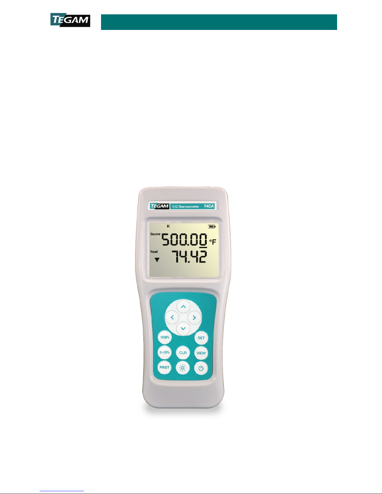
Digital Temperature Calibrator/ Thermometer 940A/945A
10 TEGAM WAY ● GENEVA, OHIO 44041 ● 440-466-6100 ● FAX 440-466-6110 ●
940A-901 Rev B
DIGITAL TEMPERATURE CALIBRATOR –
THERMOMETER QUICK START GUIDE
Digital Temperature Calibrator/ Thermometer 940A/945A
10 TEGAM WAY ● GENEVA, OHIO 44041 ● 440-466-6100 ● FAX 440-466-6110 ●
940A-901 Rev B
D
IGITAL
T
EMPERATURE
C
ALIBRATOR
–
THERMOMETER QUICK START GUIDE
Battery Installation and Replacement
Three (3) AA 1.5 V batteries are supplied with the instrument, but not installed. Read the
following battery replacement instructions before attempting to install or remove the
batteries.
To install or replace batteries:
Required Tools: Phillips Head Screwdriver
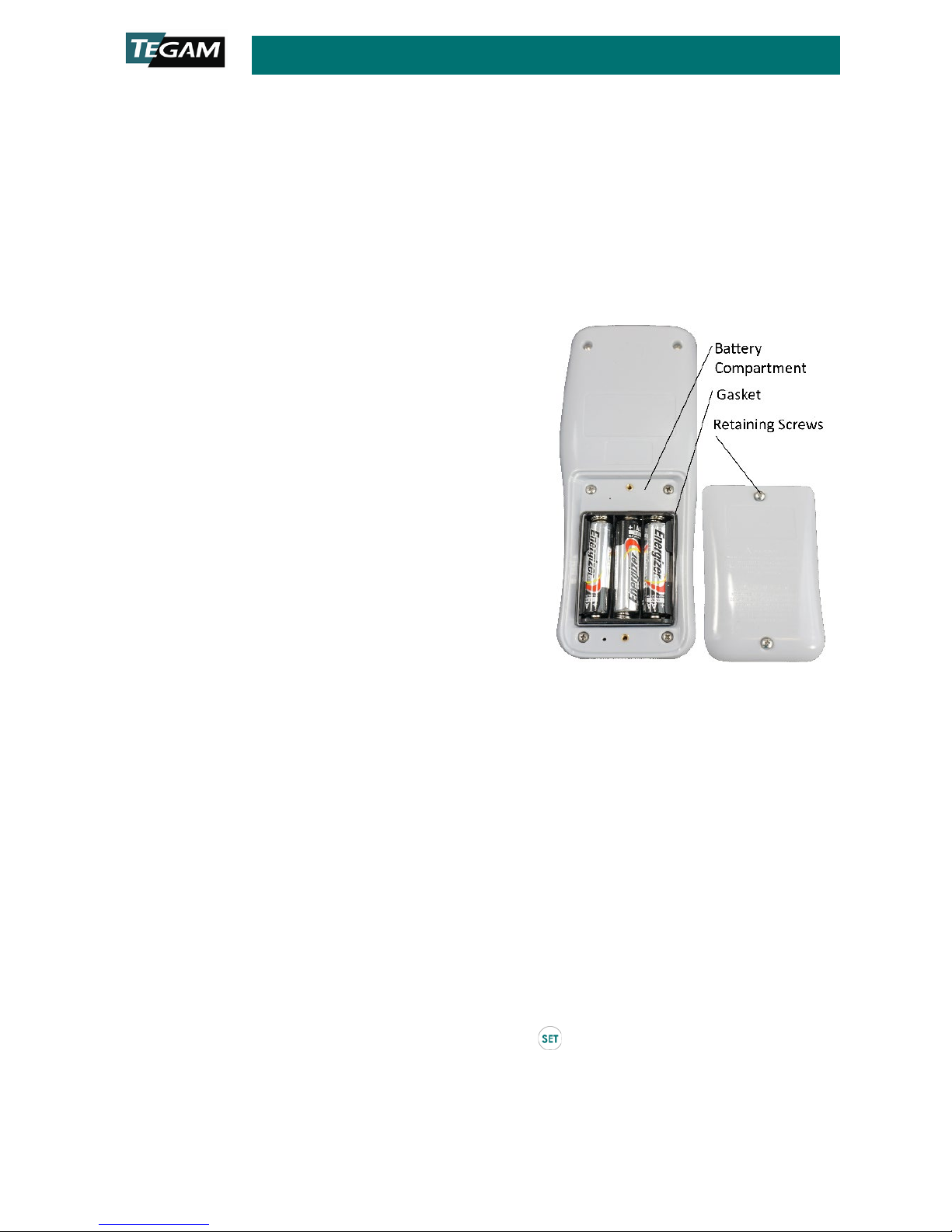
1. Identify the battery compartment located
on the back of the instrument;
2. Remove the two (2) battery compartment
retaining screws;
3. Remove the battery compartment cover;
4. If present, carefully remove old batteries
being careful to not damage the battery
contacts;
5. Observing proper polarity, install three (3)
new, AA alkaline (IEC LR6, ANSI 15)
batteries;
6. Re-install the battery cover and two (2)
retaining screws;
7. At initial power on after battery replacement, allow approximately 30 seconds for
instrument to stabilize.
Initial Power ON
8. The instrument will initially display every segment on the LCD for 2 seconds as a
test. An internal hardware, memory and battery self-test is performed during this
time.
9. Upon completing the internal tests, the instrument will immediately display the
Source and Read mode last user settings and battery indicator.
10. Set the desired measurement parameters as follows:
a. Enter the Setup Menu by pressing , hold the key down for
approximately 1.5 seconds, and then release it; Key designators followed by
(1.5s), e.g. (1.5s), indicate that the key should be pressed and held for 1.5 seconds, then released
to access the desired function.
Battery Installation

Digital Temperature Calibrator/ Thermometer 940A/945A
10 TEGAM WAY ● GENEVA, OHIO 44041 ● 440-466-6100 ● FAX 440-466-6110 ●
940A-901 Rev B
b. The active thermocouple type is flashing on the display. Use or
to select the desired thermocouple type;
c. Momentarily (do not hold) press to save your selection and move to
the next parameter;
d. The active temperature unit is flashing on the display. Use to
select the desired temperature unit (°C, °F, or mV);
e. Momentarily press to save your selection and move to the next
parameter;
f. Read Channel offset value is flashing on the display. If the temperature
probe’s offset value is known, press to set the Channel 2 probe
offset to the probe’s offset value.
g. Momentarily press to save your selection and move to Open Lead
Detection, press to toggle on/off;
h. Momentarily press to save your selection and move to Source on/off;
See “SETUP MENU CHOICES FOR °C AND °F” and/or “SETUP MENU
CHOICES FOR mV” in the table below.
i. To save the current parameter value and exit the Setup Menu, press ;
j. To disregard changes made to the current parameter value and exit the
Setup Menu, press .
k. If parameter 2, “Temperature and Voltage Units” is set as either “°C” or
“°F”, the remaining parameter choices available are in the table below
under “Setup Choices for °C and °F”. If parameter 2 is set to “mV”, the
remaining parameter choices available are in the table below under
“Setup Choices for mV”.

Digital Temperature Calibrator/ Thermometer 940A/945A
10 TEGAM WAY ● GENEVA, OHIO 44041 ● 440-466-6100 ● FAX 440-466-6110 ●
940A-901 Rev B
SETUP MENU CHOICES FOR °C AND °F
PARAMETER
AVAILABLE VALUES
Thermocouple Type K, J, T, E1
Temperature and
voltage Units
°C, °F, mV
Probe Offset ±0.1 ° increments
Open Lead detection
(old)
On / Off
Source (SourC) On / Off
If on – Set Span
Set 100% Level
Set 0% Level
If on – Set Mode
Manual
blinking
“__ __ __ __”
Fast Ramp
Slow Ramp
Step
Transfer
S
ETUP
M
ENU CHOICES FOR M
V
P
ARAMETER
A
VAILABLE
V
ALUES
Thermocouple Type
K, J, T, E1
Although still
selectable, TC type is not visible on
LCD while mV is the active unit
Temperature and
voltage Units
°C, °F, mV
Probe Offset ±0.1mV increments
Open Lead detection
(old)
On / Off
Source (SourC) On / Off
If on – Set Span
Set 100% Level
Set 0% Level
Range (rAnGE)
Range Hi mV (default)
[-15mV to +85mV]
Range Lo mV
(mV flashing)
2
[-15mV to +35mV]
1The 945A includes K,J,T,E,B,N,R,S,G,C,D,P,L,U
2Low range is for calibration verification only.

Digital Temperature Calibrator/ Thermometer 940A/945A
10 TEGAM WAY ● GENEVA, OHIO 44041 ● 440-466-6100 ● FAX 440-466-6110 ●
940A-901 Rev B
Keypad Functions
The instrument keypad is a twelve (12) key, sealed membrane keypad. Each key provides
audible and tactile user feedback when pressed. Key functions are described in the table
below.
Power instrument ON or OFF
(1.5s)
Disable auto-power OFF
(1.5s)
Enter instrument Setup Menu
While in Setup Menu, save current value and
step to next parameter
Toggle display backlight
(1.5s)
Disable backlight 30-second timeout
While in Setup Menu, discard all unsaved
changes and exit menu
(1.5s)
Delete all saved measurement data and
reset all statistics currently stored in
memory, MIN/MIX/AVG/RNG/STDEV
(1.5s)
While in PRST selection mode with PRST flashing, erases current preset
number contents
Displays in order: MIN, MAX, AVG, RNG, STDEV
While in Setup Menu, save changes and exit menu
The 10%/90% key toggles between 10% and 90% of span. The first press
of the key goes to 10%.
The 0%/+25% key manually increments the output by 25% of the defined
span for the selected TC. Once the output reaches 100% the next press of
the key will wrap around to 0%.
Once in Preset, single press saves and exits leaving the selected preset
number active
(1.5s)
Enters the Preset selection mode
Up and Down Buttons: Increment/Decrement currently selected Source digit
by 1.
Left and Right Buttons: Move active Source digit indicator by 1 place left or
right.
Keypad Button Functional Description
The , , , and keys have multiple functions which can be accessed by
momentarily pressing the key, or alternatively, by pressing and holding the key for
approximately 1.5 seconds. Throughout this Operation Manual, the press and hold sequence
is indicated by the key designator followed by the subscript (1.5s). For instance, (1.5s)
Digital Temperature Calibrator/ Thermometer 940A/945A
10 TEGAM WAY ● GENEVA, OHIO 44041 ● 440-466-6100 ● FAX 440-466-6110 ●
940A-901 Rev B
indicates that the key should be pressed and held for 1.5 seconds, then released to
access the desired function.
Operating Modes
The instrument has five (5) operating modes including manual operation. The operating
modes are Manual, Fast ramp, slow ramp, step and transfer.
Presets: Save, Recall and Erase
There are 20 presets in the instrument numbered 0 – 19. The presets allow the user to save
the parameters chosen during setup. There are 3 preset actions. The user can save,recall
or erase.
When a preset is saved, the current operating options are stored in one of the 20 selected
presets. The operating options include:
•Thermocouple Type
•Units
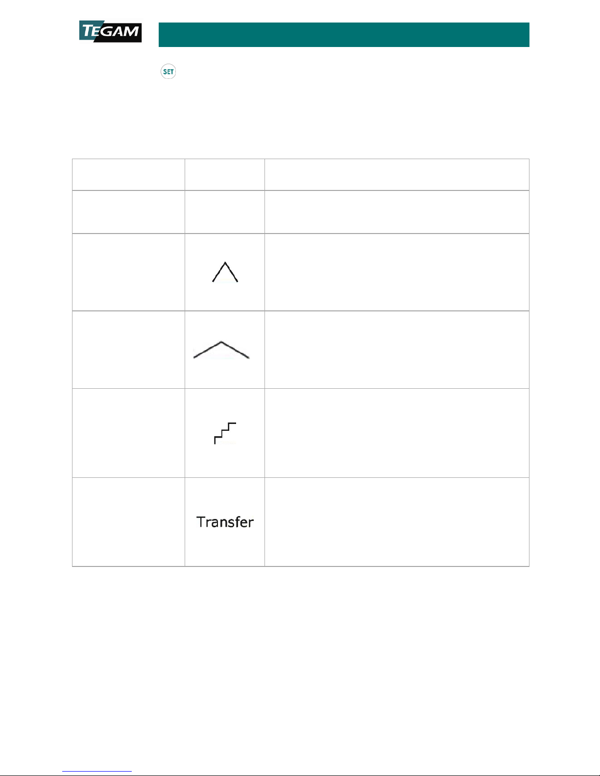
OPERATING MODE
D
ISPLAY
INDICATOR
DESCRIPTION
Manual
blinking
“__ __ __ __”
Instrument operates by outputting a voltage that
corresponds to the set temperature or
millivoltage.
Fast Ramp
Instrument Ramps the output temperature or
millivoltage from 0% of span to 100% of span and
back to 0% of span in 50 units per second. This
repeats until stopped. Any other key press will
stop the output at the existing value (temperature
or millivoltage) and clear the fast ramp setting.
Slow Ramp
Instrument Ramps the output temperature or
millivoltage from 0% of span to 100% of span and
back to 0% of span in 5 units per second. This
repeats until stopped. Any other key press will
stop the output at the existing value (temperature
or millivoltage) and clear the slow ramp setting.
Step
Instrument Ramps the output temperature or
millivoltage from 0% of span to 100% of span and
back to 0% of span stepping at 10% increments,
dwelling 5 seconds at each step. This repeats
until stopped. Any other key press will stop the
output at the existing value (temperature or
millivoltage) and clear the Step ramp setting.
Transfer
Instrument sets the source output (temperature
or millivoltage) equal to the value on the “Read”
channel, (channel 2). This is an offset corrected
value. SOURCE output = READ voltage + CJC
voltage. This mode would be used for
troubleshooting systems and readouts. The
“Transfer” icon will blink and illuminate if selected.

Digital Temperature Calibrator/ Thermometer 940A/945A
10 TEGAM WAY ● GENEVA, OHIO 44041 ● 440-466-6100 ● FAX 440-466-6110 ●
940A-901 Rev B
•Offset
•Open Lead Detection Status
•100% and 0% Span Settings
•Operating Mode: Fast Ramp, Slow Ramp, Step or Transfer
To save a preset
Press the (1.5s). The preset number will start flashing. Use the to move to the
preset number location you want to use to store the current operating options. Press the
. The current operating options are now saved in the chosen preset location and the
flashing stops.
To recall a preset
Press the button. “PRST” will begin to flash. Use the to move to the desired
saved preset, 0-19. When the desired preset is reached, press the preset button again to
exit. The instrument will only display the numbers where presets are stored. For example:
If there are presets stored in 3 and 10 and all others are empty, in this case the would
only toggle between and display 3 and 10.
To erase a preset
To erase a preset it must first be recalled by following the “To recall a preset” steps above.
Once the desired preset is recalled, press the (1.5s). The preset number should now be
flashing. While the preset number is flashing, press (1.5s). “CLEAr” will appear on the
LCD momentarily. The location is now empty and will not appear with any of the saved
presets when trying to recall a preset.

TEGAM INC.
10 TEGAM WAY
GENEVA, OHIO 44041
CAGE Code: 49374
WEB: http://www.tegam.com
Other manuals for 940A
1
This manual suits for next models
1
Table of contents
Other Tegam Thermometer manuals


