Teguar TB-5745 User manual
TB-5745
Vertical Application System 8/9th Gen. Intel Core-I
and Xeon® E Platform
User Manual
Release Date Revision
MARCH 2021 V1.0

TB-5745 Vertical Application System User Manual
1
Revision History
Reversion Date Description
1.0 2021/03/22 Official Version - Sam

TB-5745 Vertical Application System User Manual
2
Warning!________________________
This equipment will generate, use and radiate radio frequency energy and if
not installed and used in accordance with the instructions manual, it may cause
interference to radio communications. It has been tested and found to comply
with the limits for a Class A computing device pursuant to FCC Rules, which is
designed to provide reasonable protection against such interference when
operated in a commercial environment. Operation of this equipment in a
residential area is likely to cause interference in which case the user with its own
expense will be required to take whatever measures may be required to correct
the interference.
Electric Shock Hazard – Do not operate the machine with its back cover removed.
There are dangerous high voltages inside.

TB-5745 Vertical Application System User Manual
3
Packing List
Accessories (as ticked) included in this package are:
□Adaptor
□Driver & manual CD disc
□Other.___________________(please specify)

TB-5745 Vertical Application System User Manual
4
Safety Precautions
Follow the messages below to prevent your systems from damage:
◆Avoid exposing your system from static electricity on all occasions.
◆Prevent electric shock. Don‘t touch any components inside of this unit
when the power is on. Always disconnect power when the system is not
in use and before servicing.
◆Disconnect power when you change any hardware devices. For instance,
when you connect a jumper or install any cards, a surge of power may
damage the electronic components or the whole system.

TB-5745 Vertical Application System User Manual
5
Table of Contents
Revision History…………………………………………………………………………………………………….1
Warning…………………............................................…………………………….……………………2
Packing List…………………………………….…………………………………………………....................3
Safety Precautions…………………………………….…………….…..……………………....................4
Chapter 1 Getting Started
1.1 Features……..…………………..………………………...…………………………..7
1.2 Specifications…..………………...………………………………………………….7
1.3 Dimensions……..…………………....……………………………………………...9
1.4 Brief Description of TB-5745 series..….…..…………………….……10
Chapter 2 Hardware
2.1 Motherboard Introduction…………………….....…………………….....13
2.2 Specifications…………………………..…………..………………………………13
2.3 Motherboard Dimensions….……..…………..……………………………16
2.4 Jumpers and Connectors Location……….……………………………...17
2.5 Jumpers Setting and Connectors…………..………………………..……19
Chapter 3 BIOS Setup
3.1 Operations after POST Screen…...……..……...…………………………42
3.2 BIOS Setup Utility……………………………..………………………………….42
3.3 Main Settings…………………………………..…..………………………………43
3.4 Advanced Settings………………………………………….…………………...44
3.5 Chipset Settings…………………………….………….………………………...55
3.6 Security Settings……..…………………………..……………….……………..92
3.7 Boot Settings………..………………….…….…………….……………………..94
3.8 Save & Exit Settings………………………..……………..…………………....95
Chapter 4 Installation of Drivers
4.1Intel® H170 Chipset……………………….…………………...……………98
4.2 Intel® HD Graphics 530 Chipset…..……………….……..……….…....100
4.3 Realtek ALC269 HD Audio Driver Installation……..……..……….104
4.4 Intel® Management Engine Interface………............................106
Chapter 5 Mounting Suggestions
5.1Din Rail Mount….….………....……………...………….………………109
5.2Wall Mount….….………....…………………..………….………………112

TB-5745 Vertical Application System User Manual
6
Figures
Figure 1.1: Dimensions of TB-5745…..….……….………….…………………………...9
Figure 1.2: Overview of TB-5745……….….…..……..………………………………….11
Figure 2.1: Motherboard Dimensions ………..……………………..16
Figure 2.2: Jumpers and Connectors Location-Board Top……………………..17
Figure 2.3: Jumpers and Connectors Location-Board Bottom……………….18
Figure 5.1: Desktop of TB-5745………………..……….………….…………………..109
Figure 5.4: Wall Mount of TB-5745……….….…..……..……………………………112
TB-5745 Vertical Application System User Manual
7
Chapter 1 Getting Started
1.1 Features
Vertical System for Artificial Intelligent applications such as Machine Vision,
Edge Computing, Machine Learning/Inference, Robotic Control, Automation,
and any industrial need.
High performance CPU of Intel 8/9th Gen. Core-i Processor and Xeon® E
Processors.
Large memory support with DDR4 (2400MHz) SO-DIMM up to 64GB.
Removable Drive-bays for easy data storage maintenance.
Support extensive GPU Card expansion for Hard-computing requirement (with
GPU Card Holder).
Mainboard CPU Fan-less Design for some Processors and GPU Card Expansion
with Smart Fan support.
Flexible expansion features through I/O module design with mini-PCIe and
PCIe/PCI Add-on card support.
1.2 Specifications
TB-5745
System
CPU Intel 8/9th Gen. Core i3/i5/i7 Processors (without turbo operation)
Intel® Xeon® E Processors
Chipset C246
Memory 2 x 260-pin stacked DDR4 (2400MHz) SO-DIMM memory sockets,
Dual channel/bank, up to 64GB support.
Outside IO Port
Default I/O Ports 4 x USB 3.1 Gen.2 (Type A, with Lock-hole)
2 x USB2.0 (typeA)
1 x USB2.0 (Internal Type A in backside for Dongle)
2 x GbE LAN RJ-45
1 x DP 1.2 port
1 x HDMI port

TB-5745 Vertical Application System User Manual
8
2 x RS-232/422/485 (COM1/COM2, DB9, default RS-232)
1 x Line-out
1 x Mic-in via TB-595
1 x 8-bit GPIO (4 x in, 4 x out, Isolated 2500Vrms, NPN/PNP Selected,
Default NPN) via TB-595
Storage Space
Storage Mainboard Backside connectors:
4x SATA3 channels (RAID 0/1/5/10):
(a) 2 x 2.5” SATA3 HDD/SSD with Removable Drive-bays by default (for
5~7mm HDD/SSD)
(b) 2 x 2.5” SATA3 HDD/SSD for expansion, Drive-bay optional (for
5~7mm HDD/SSD)
1 x M.2 Key (2242/2280, for PCIe x 4 NVMe support)
Expansion
Expansion Slot Mainboard Backside Expansion:
2 x Full-size mini-PCIe slots
1 x micro SIM socket
PCIe Expansion via TB-594E82E161, Power support up to 400W.
1 x PCIe-4 in x8 socket (slot#1, GEN.3)
1 x PCIe-4 in x8 socket (slot#2, GEN.3)
1 x PCIe-16 (slot#3, GEN.3)
Power
Power Input 1 x 3-Pin Terminal Block for 24V DC power input (MB Maximum Power
support to 250W)
1 x 3-Pin Terminal Block for 2nd power extension (optional, 24V DC IN,
4ch, 100W/ch, Maximum power support up to 400W)
ACC Ignition (optional)
1 x Power Button with LED light
1 x 2-pin Power Switch Connector
Misc
Misc
1 x TPM2.0
1 x Watchdog Timer (256 steps)
1 x Thermal Copper for PCBA Thermal Detection
3 x SMA holes for Wi-Fi or Wireless 4G LTE/GPS antennas
Mechanical
Construction
Titanic Metal color for the aluminum Heat-sink.
Standard Black for the metal steel chassis.
Mounting Desktop (default)/Wall Mount(bracket-optional)

TB-5745 Vertical Application System User Manual
9
Dimensions 350 x 200 x 200 mm (LxWxH)
Net Weight
6.5Kg
Ventilation 3 x 80x80mm Ventilation windows (Default)
2 x 80x80mm Smart Fans on the top side for hot-air out (Default)
1 x 120x120mm Smart Fan outside on top of Heat-sink for CPU hot-air
blow (Optional – required for high TDP CPU)
Environmental
Operating
Temperature
0~50°C(for i3/i5 model)
(non-turbo, without GPU operation)
0~45°C(for i7 model)
(non-turbo, without GPU operation)
Storage Temperature
-40~85
°C
Operating Humidity 10 to 90% @ 30°C, non-condensing
Storage Humidity
10 to 90% @ 40
°C
, non-condensing
Certification Designed to meet CE / FCC Class A(CCC, UL, and other options by
request)
Operating System
Support
Microsoft® Win10 IoT, Windows 10 Pro, Linux 4.20.2+

TB-5745 Vertical Application System User Manual
11
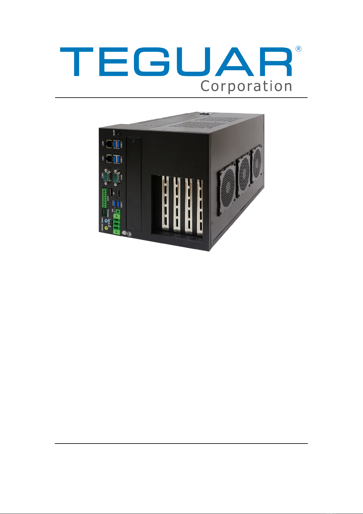
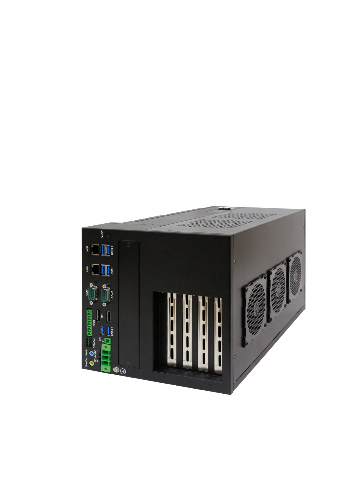
1.4 Brief Description of TB-5745
TB-5745 is designed with MB CPU fan-less and GPU card expansion with smart
fan support. It is powerful with Intel 8th Generation Core i3/i5/i7 processor and Intel
Xeon-E processors, and it supports 2 x 260-pin DDR4 SO-DIMM up to 64GB memory.
They come with 4 x USB 3.1 Type A, 2 x USB 2.0 Type A, 2 x LAN, 1 x DP, 1 x HDMI, 2 x
COM ports, 1 x line-out, and 1 x Mic-in. TB-5745 supports easy-accessible 4 x 2.5”
SATA3 HDD space and 24V DC power input. TB-5745 has up to 2 x full-size mini-PCIe
slot and 1 x micro SIM socket for expansion. It is titanium metal aluminum heatsink
and black steel chassis design, and can be placed on desktop or wall-mounted. The
TB-5745 works well with our other expansion products and can provide an easy way
to perform industrial control.
Figure 1.4: Appearance of TB-5745
TB-5745 Vertical Application System User Manual
12
Chapter 2 Hardware
2.1 Motherboard Introduction
The TB-5745 mainboard is a non-standard industrial motherboard developed on the
Intel C246, which provides abundant peripheral interfaces to meet the needs of
different customers. Also, it features dual GbE ports, 6-COM ports and two mPCIE
ports in configuration. To satisfy the special needs of high-end customers, the
mainboard is designed with 164-pin PCIe x 16 slot expansion interface, which
includes 98pin PCIex8 interface and 64 pin PCIex4 slot interface. The mainboard is
designed to be used in various sectors of industrial control or high-end visual
automation.
2.2 Specifications
Specifications
Board Size
194mm x 280mm
CPU Socket LGA 1151 Socket
CPU Support
Intel 8th /9th Core i3/i5/i7 and /Xeon E Processor
Intel® Core™ I7-8700T 2.40GHz (up to 4.00GHz)35W
Intel® Core™ I7-8700, 3.20GHz (up to 4.60GHz)65W
Intel® Core™ I3-9100TE 2.20GHz (up to 3.30 GHz)35W
Intel® Core™ I3-9100E 3.10GHz (up to 3.70GHz)65W
Intel® Core™ I5-9500TE 2.20GHz (up to 3.60GHz)35W
Intel® Core™ I5-9500E 3.00GHz (up to 4.20GHz)65W
Intel® Core™ I7-9700TE 1.80GHz (up to 3.80GHz)35W
Intel® Core™ I7-9700E 2.60GHz (up to 4.40GHz)65W
Intel® Xeon E-2278GEL 2.00GHz (up to 3.90GHz)35W (project
based)
Intel® Xeon E-2278GE 3.30GHz (up to 4.70GHz)80W (project
based)
Intel® Xeon E-2278G 3.40GHz (up to 5.00GHz)80W (project based)
Chipset
Intel®C246 Chipset
Memory Support 2 x SO-DIMM (260pins)
up to 64GB DDR4 2666 MHz FSB(I7-8700T/I7-8700)

TB-5745 Vertical Application System User Manual
13
up to 32GB DDR4 2400 MHz FSB(I3-9100TE/I3-9100E)
up to 64GB DDR4 2666 MHz FSB
(I5-9500TE/I5-9500E/I7-9700TE/I7-9700E)
up to 64GB DDR4 2666 MHz FSB(E2278GEL/E2278GE/E2278G)
Graphics
Intel® UHD Graphics 630
Intel® UHD Graphics P630 (E2278G)
Display Mode 1 x HDMI interface (HDMI 1.4)
1 x DP interface
Support
Resolution
Up to 4096 x 2304 for HDMI (I7-8700T/I7-8700)
Up to 4096 x 2160 for HDMI
Up to 4096 x 2304 for DP
Double Display
HDMI + DP
Super I/O
Nuvoton NCT6106D
BIOS AMI/UEFI BIOS
Storage
4 x SATA3.0 Connector (SATA1/SATA2/SATA3/SATA4)
1 x NGFF(M.2)M-Key, support 2242/2280
Ethernet
1 x PCIe GbE LAN via Intel I210AT
1 x PCIe GbE LAN via Intel I219-LM, Support Intel® AMT
Technology (option)
USB
4 x USB 3.0/2.0 stack ports for external
(USB 3.0: USB3-3/USB3-4/USB3-5/USB3-6)
(USB 2.0: USB2-3/USB2-4/USB2-5/USB2-6)
2 x USB 2.0 stack ports for external (USB2.0: USB2-1/USB2-2)
1 x USB 2.0 Single port for internal (USB2-8)
2 x USB 2.0, 2x5Pin header(USB2-9/USB2-10)
2 x USB 2.0, 2x5Pin header(USB2-11/USB2-12)
1 x USB 2.0 internal for M-PCIE1 (USB2-13)
1 x USB 2.0 internal for M-PCIE2 (USB2-14)
Serial
1 x RS232/RS422/RS485 port, DB9 connector for external (COM1)
Pin 9 w/5V/12V/Ring select
1 x RS232 port, DB9 connector for external (COM2)
Pin 9 w/5V/12V/Ring select
4 x RS232 select header for internal MIO2 (COM3/4/5/6)
Digital I/O
8-bit digital I/O by pin header (MIO1)

TB-5745 Vertical Application System User Manual
14
4-bit digital input
4-bit digital output
Battery
Support CR2477 Li battery by 2-pin header (1000mAh)
Audio Support Audio via Realtek ALC269Q-VC HD audio codec
Support Line-in/Line-out/MIC-in by Pin header(MIO1)
Support a stereo Class-D Speaker Amplifier with 2 watt per
channel output power, by 1 x 4-pin header (SPK1)
Expansion Bus 1 x PCI-express x8 extend by 98 pin slot(PCIE_8x1)
1 x PCI-express x16 extend by 164 pin slot(PCIE_16x1)
1 x mini-PCI-express slot (MPCIE1)
1 x mini-PCI-express slot (MPCIE2)
Power
Management
via 3-pin Connector (input)
Switches and LED
Indicators
Power on/off switch by PS_ON2 and BT1 and PS_ON1
Power LED status by PS_ON2
External I/O Port
2 x COM Ports(COM1/COM2)
4 x USB 3.0 Ports(stack)
2 x USB 2.0 Ports(stack)
2 x RJ45 GbE LAN Ports
1 x HDMI interface
1 x DP interface
SIM
1 x SIM Card holder(option)
TPM
Infineon’s Trusted Platform Module(TPM2.0)
Note: Only support Windows 10
FAN
3 x FAN connector:
2x 1x4Pin wafer (FAN_1/FAN_2)
1x Pin header by MIO1 (CPU FAN)
Temperature
Operating: -20℃to 70℃(Motherboard only)
Storage: -40℃to 85℃
Humidity
10% - 90%, non-condensing, operating
Power
Consumption
Total Power Design 450W

TB-5745 Vertical Application System User Manual
15
EMI/EMS Meet CE/FCC class A
PB-429
Board Size: 100x65mm
1 x 3-pin power input connector
2 x 2*2pin power output connector
TB-595
Board Size: 70x32mm
8-bit digital I/O by connector, isolated(CN1)
4-bit digital Input
4-bit digital Output
1 x Switch, NPN/PNP mode select via dip
Support Line-Out by Jack
Support Line-In by Jack
1 x 4-Pin wafer for CPU FAN
TB-594E42E161
Board Size: 250x130mm
1 x PCIe x4 Slot (98Pin)
1 x PCIe x16 Slot (164Pin)
2 x 2*4 pin power DC12V output connector
TB-5745 Vertical Application System User Manual
16
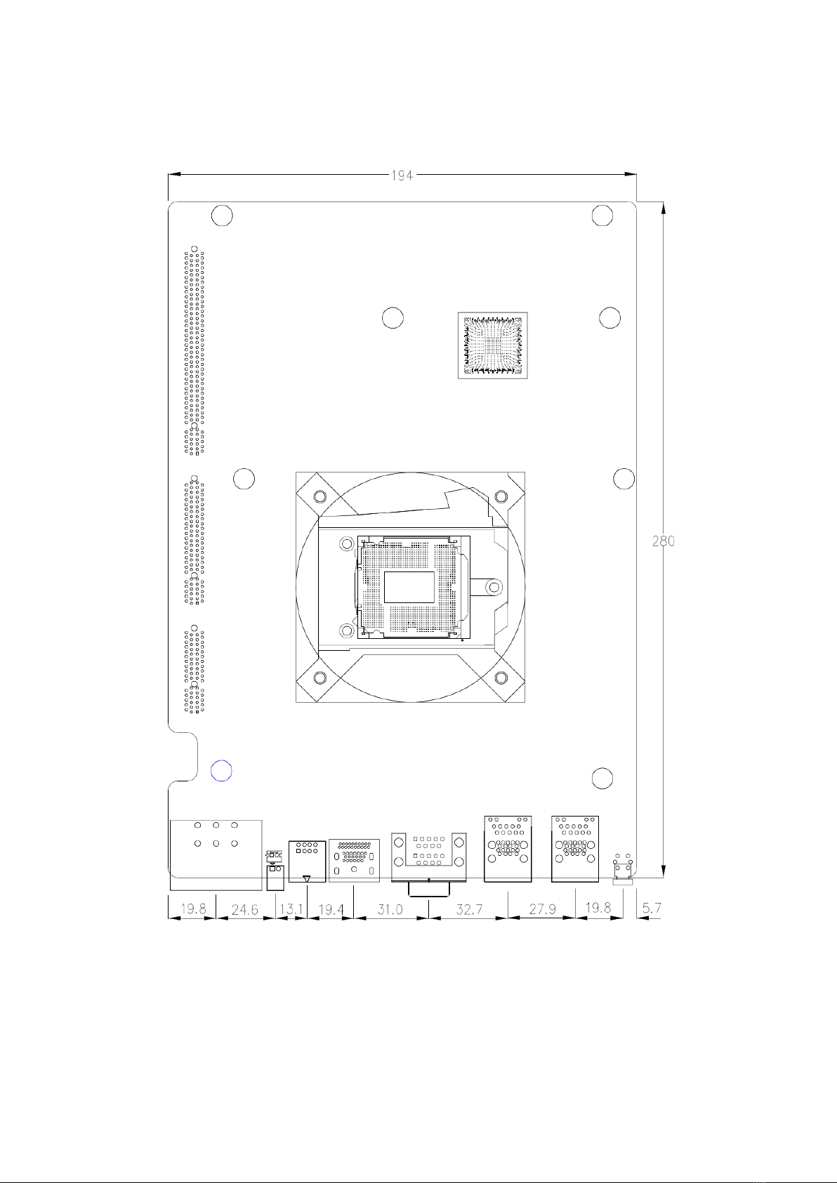
2.3 Motherboard Dimension
(units :mm)
Figure 2.1: Motherboard Dimensions


TB-5745 Vertical Application System User Manual
18
Figure 2.3: Jumpers and Connectors Location- Board Bottom
TB-5745 Vertical Application System User Manual
19
2.5 Jumpers Setting and Connectors
1. SW1-2/SW1-3:
CMOS clear switch, CMOS clear operation will permanently reset old BIOS
settings to factory defaults.
SW1 CMOS
Pin2 OFF
NORMAL (Default)
Pin2 ON Clear CMOS
Pin3 OFF NORMAL (Default)
Pin3 ON
Clear CMOS
Procedures of CMOS clear:
a) Turn off the system and unplug the power cord from the power outlet.
b) To clear the CMOS settings, use the switch to Pin2 on for about 3 seconds
then move the switch Pin2 and Pin3 off.
c) Power on the system again.
d) When entering the POST screen, press the <DEL> key to enter CMOS Setup
Utility to load optimal defaults.
e) After the above operations, save changes and exit BIOS Setup.
2. BAT2:
(1.25mm Pitch 1x2 wafer Pin Header) 3.0V Li Battery is embedded to provide
power for CMOS.
Pin# Signal Name
Pin1 Ground
Pin2
VCC_RTC
3. SW1-1:
Switch, DC Power input setting, Power on/off button and Auto Power on switch
setting.
SW1
Function(DC input /DC_IN1)
Pin1 ON Auto Power on (Default)
Table of contents
Popular Industrial PC manuals by other brands


Dell
Dell Embedded Box PC 5000 Installation and operation manual

IBASE Technology
IBASE Technology ASB200-918 Series user manual

Lenovo
Lenovo ThinkCentre M90q Hardware Maintenance Manual

IXXAT
IXXAT Econ 100 Hardware manual

Kontron
Kontron KBox A-151-TGL user guide

AXIOMTEK
AXIOMTEK ICO500-518 Series user manual