Teguar TP 40 Series User manual

USER MANUAL
VERSION 4.0 March 2019
TP/TM-XX40
Panel PC
Hardware System

ii
Copyright 2019
All Rights Reserved
Manual Version 4.0
The information contained in this document is subject to change without notice.
We make no warranty of any kind with regard to this material, including, but not limited
to, the implied warranties of merchantability and fitness for a particular purpose.
We shall not be liable for errors contained herein or for incidental or consequential
damages in connection with the furnishing, performance, or use of this material.
This document contains proprietary information that is protected by copyright. All rights
are reserved. No part of this document may be photocopied, reproduced or translated
to another language without the prior written consent of the manufacturer.
TRADEMARK
Intel®, Pentium® and MMX are registered trademarks of Intel® Corporation.
Microsoft® and Windows® are registered trademarks of Microsoft Corporation.
Other trademarks mentioned herein are the property of their respective owners.
Safety
IMPORTANT SAFETY INSTRUCTIONS
1. To disconnect the machine from the electrical power supply, turn off the power switch
and remove the power cord plug from the wall socket. The wall socket must be easily
accessible and in close proximity to the machine.
2. Read these instructions carefully. Save these instructions for future reference.
3. Follow all warnings and instructions marked on the product.
4. Do not use this product near water.
5. Do not place this product on an unstable cart, stand, or table. The product may fall,
causing serious damage to the product.
6. Slots and openings in the cabinet and the back or bottom are provided for ventilation
to ensure reliable operation of the product and to protect it from overheating. These
openings must not be blocked or covered. The openings should never be blocked by
placing the product on a bed, sofa, rug, or other similar surface. This product should
never be placed near or over a radiator or heat register or in a built-in installation
unless proper ventilation is provided.
7. This product should be operated from the type of power indicated on the marking label.
If you are not sure of the type of power available, consult your dealer or local power
company.
8. Do not allow anything to rest on the power cord. Do not locate this product where
persons will walk on the cord.
9. Never push objects of any kind into this product through cabinet slots as they may
touch dangerous voltage points or short out parts that could result in a re or electric
shock. Never spill liquid of any kind on the product.
10.The Clinical PC can be cleaned in accordance with normal clinical cleaning practices,
including wiping with water or medical grade wipes, provided no substance containing
acids or cleaning alkali liquids is used.
11.Medical grade wipes must not contain more than 80% alcohol content measured
against the total content of the wipe.

iii
Sécurité
INSTRUCTIONS IMPORTANTES RELATIVES À LA SECURITE
1. Pour débrancher la machine de l’alimentation électrique, éteignez l’interrupteur
d’alimentation et retirez le cordon d’alimentation de la prise murale. La prise murale
doit être facilement accessible et à proximité de la machine.
2. Lisez attentivement ces instructions. Conservez ces instructions pour une référence
future.
3. Suivez tous les avertissements et les instructions indiquées sur le produit.
4. Ne pas utiliser ce produit à proximité de l’eau.
5. Ne pas placer ce produit sur un chariot, un support ou une table. Le produit peut
tomber,causant de graves dommages à l’appareil.
6. Les fentes et les ouvertures dans le boîtier, l’arrière ou le fond sont prévues pour
la ventilation an d’assurer un fonctionnement able du produit et le protéger de la
surchauffe. Ces ouvertures ne doivent pas être obstruées ou couvertes. Les ouvertures
ne doivent jamais être bloquées en plaçant l’appareil sur un lit, un canapé, un tapis
ou autre surface similaire. Ce produit ne doit jamais être placé : à proximité ou sur un
radiateur, sur un registre de chaleur ou dans une installation intégrée à moins qu’une
ventilation adéquate soit prévue.
7. Ce produit doit être utilisé avec le type d’alimentation indiqué sur l’étiquette.Si
vous n’êtes pas sûr du type d’alimentation disponible, consultez votre revendeur ou
représentant local de l’entreprise.
8. Ne laissez rien reposer sur le cordon d’alimentation. Ne placez pas ce produit là oùdes
personnes peuvent marcher sur le cordon.
9. N’introduisez jamais d’objets d’aucune sorte dans ce produit à travers les fentes du
coffret car ils pourraient entrer en contact avec des points sous tension dangereux ou
court-circuiter des pièces. Ne renversez jamais de liquide d’aucune sorte sur le produit.
CE MARK
This device complies with the requirements of the EEC directive 2014/30/EU with
regard to “Electromagnetic compatibility” and 2014/35/EU “Low Voltage Directive”.
FCC
This device complies with part 15 of the FCC rules. Operation is subject to the following
two conditions:
(1) This device may not cause harmful interference.
(2) This device must accept any interference received, including interference that may
cause undesired operation.

iv
CAUTION ON LITHIUM BATTERIES
There is a danger of explosion if the battery is replaced incorrectly. Replace only
with the same or equivalent type recommended by the manufacturer. Discard used
batteries according to the manufacturer’s instructions.
Battery Caution
Risk of explosion if battery is replaced by an incorrectly type. Dispose of used battery
according to the local disposal instructions.
Safety Caution
Note: To comply with IEC60950-1 Clause 2.5 (limited power sources, L.P.S) related
legislation, peripherals shall be 4.7.3.2 “Materials for re enclosure” compliant.
4.7.3.2 Materials for re enclosures
For MOVABLE EQUIPMENT having a total mass not exceeding 18kg.the material of a
FIRE ENCLOSURE, in the thinnest signicant wall thickness used, shall be of V-1 CLASS
MATERIAL or shall pass the test of Clause A.2.
For MOVABLE EQUIPMENT having a total mass exceeding 18kg and for all STATIONARY
EQUIPMENT, the material of a FIRE ENCLOSURE, in the thinnest significant wall
thickness used, shall be of 5VB CLASS MATERIAL or shall pass the test of Clause A.1
AVERTISSEMENT SUR LES BATTERIES AU LITHIUM
Il y a un danger d’explosion si la batterie n’est pas remplacée correctement.
Remplacez-la uniquement par une batterie identique ou de type équivalent
recommandée par le fabricant.les batteries usagées doivent être mises au rebut
conformément aux instructions du fabricant.
Avertissement Batterie
Risque d’explosion si la batterie est remplacée par un élément incompatible.
Jetez les batteries usagées selon les instructions des dispositions locales .
Avertissement de sécurité
Remarque: Pour répondre à la norme IEC60950-1 alinéa 2.5 (sources d’énergie limitées,
LPS) liés la législation, les périphériques doivent être conforme 4.7.3.2 “Matériaux pour
enceinte coupe-feu»
4.7.3.2 “Matériaux pour équipements coupe-feu»
Pour les équipements mobiles ayant une masse totale n’excédant pas 18kg :
Les matériaux d’un équipement coupe-feu, dans l’épaisseur de paroi retenue la plus
signicativement mince, doivent être des matériels de CLASSE V-1 ou doivent passer le
test de l’article A.2.
v
Pour équipements mobiles ayant une masse totale supérieure à 18 kg et pour tous les
équipements FIXES :
Les matériaux d’un équipement coupe-feu dans l’épaisseur de paroi retenue la plus
signicativement mince, doivent être des matériels de CLASSE V-1, doivent être de
classe Matériel 5VB ou doivent passer le test de l’article A.1
LEGISLATION AND WEEE SYMBOL
2012/19/EU Waste Electrical and Electronic Equipment Directive on the treatment,
collection, recycling and disposal of electric and electronic devices and their
components.
The crossed dust bin symbol on the device means that it should not be disposed of
with other household wastes at the end of its working life. Instead, the device should
be taken to the waste collection centers for activation of the treatment, collection,
recycling and disposal procedure.
To prevent possible harm to the environment or human health from uncontrolled waste
disposal, please separate this from other types of wastes and recycle it responsibly to
promote the sustainable reuse of material resources.
Household users should contact either the retailer where they purchased this product,
or their local government ofce, for details of where and how they can take this item for
environmentally safe recycling.
Business users should contact their supplier and check the terms and conditions of
the purchase contract.
This product should not be mixed with other commercial wastes for disposal.
vi
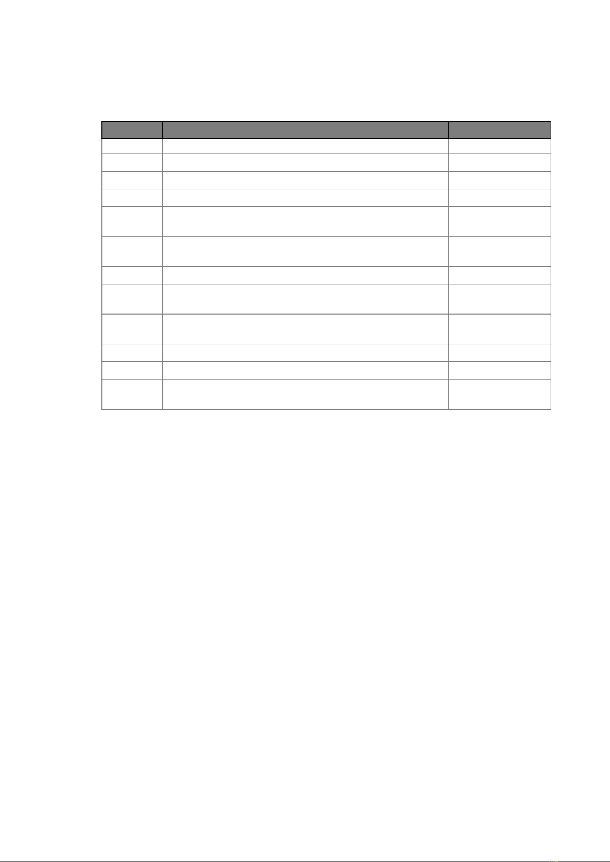
Revision Description Date
1.0 • Initial release April 2011
1.1 • IdeaCom touch driver installation added June 2011
1.2 •3040 MB added March 2012
1.3 •2040 MB added June 2012
1.4 •2040 MB added
•1540 MB and 2040 MB removed June 2013
2.0 •Add the French language of the Safety, Warning &
Caution in the page iii~v January 2014
2.1 • Add 3040 MB September 2014
2.2 •2040 MB removed
•4040 MB added July 2015
2.3 •Remove RJ11 port and relevant setting from
4040 and 3040 MB December 2015
3.0 •5040 MB added November 2016
3.1 • Important safety instruction updated March 2017
4.0 •3040 MB removed
•5040 MB added March 2019
Revision History
Changes to the original user manual are listed below:

vii
Table of Contents
1. Packing List.................................. 1
1-1. Standard Items................................................................1
1-2. Optional Items .................................................................2
2. System View.................................. 3
2-1. Front & Side View ............................................................3
2-2. Rear View.........................................................................3
2-3. I/O view............................................................................4
2-4. Dimensions......................................................................6
2-4-1. 15.6" System .................................................................... 6
2-4-2. 18.5" System.................................................................... 6
2-4-3. 21.5" System .................................................................... 6
3. System Assembly ......................... 7
3-1. Open the Chassis Cover..................................................7
3-2. RAM Module Replacement.............................................8
3-3. HDD Replacement ..........................................................9
4. Specication................................ 10

viii
5. Conguration............................... 18
5-1. 3040 Motherboard Layout ............................................18
5-1-1. Motherboard Layout........................................................18
5-1-2. Connectors & Functions .................................................19
5-1-3. Jumper Setting ................................................................20
5-2. 4040 V2.1 Motherboard Layout....................................22
5-2-1. Motherboard Layout........................................................22
5-2-2. Connectors & Functions .................................................23
5-2-3. Jumper Setting ................................................................ 24
5-3. 4040 V4.0 Motherboard Layout....................................26
5-3-1. Motherboard Layout........................................................26
5-3-2. Connectors & Functions ................................................. 27
5-3-3. Jumper Setting ................................................................28
5-4. 5040 Motherboard ........................................................29
5-4-1. Motherboard Layout........................................................29
5-4-2. Connectors & Functions .................................................30
5-4-3. Jumper Setting ................................................................ 31
5-5. 5040 Motherboard .......................................................33
5-5-1. Motherboard Layout........................................................33
5-5-2. Connectors & Functions .................................................34
5-5-3. Jumper Setting ................................................................35

ix
The page is intentionally left blank.
1
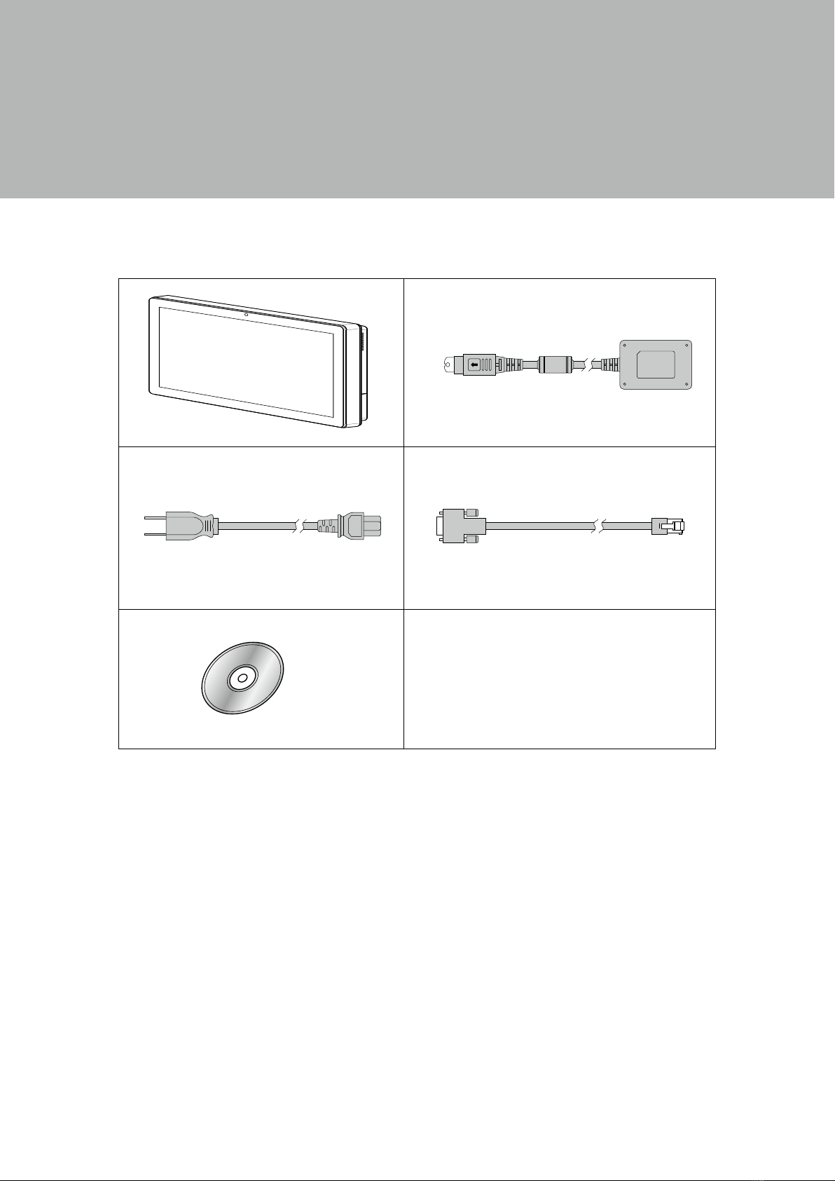
1. Packing List
1-1. Standard Items
a. System
b. Power adapter
c. Power cord
d. RJ45-DB9 cable (x2)
e. Driver bank
a. b.
c. d.
e.
Note: Power cord will be supplied differently according to various region or country.

2
1-2. Optional Items
MSR

3
2. System View
2-1. Front & Side View
1. Touch screen
2. Built-in web cam
2-2. Rear View
1
3
2
3. Ventilation
4. MSR cable hole
4
5. VESA mounting holes
6. Cable cover
7. Safety label
5
7
6
4
bcdefghijk
m
l
a
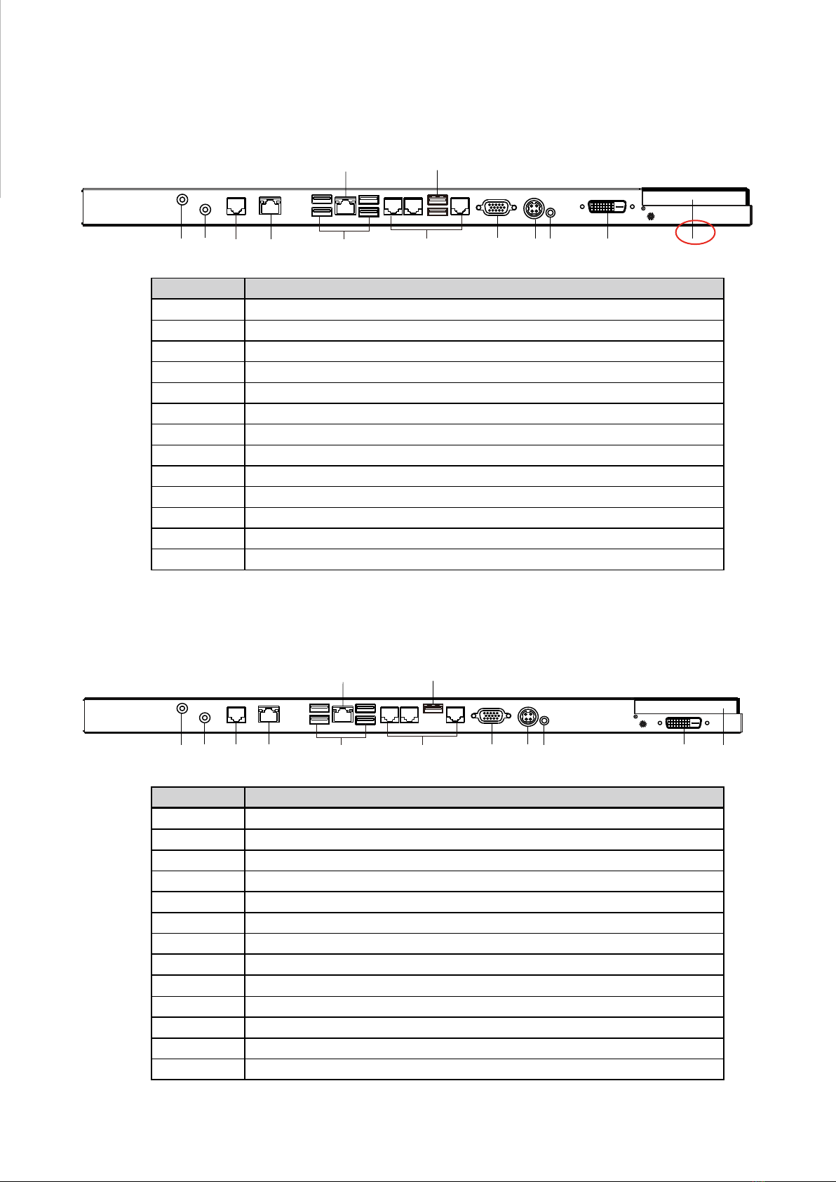
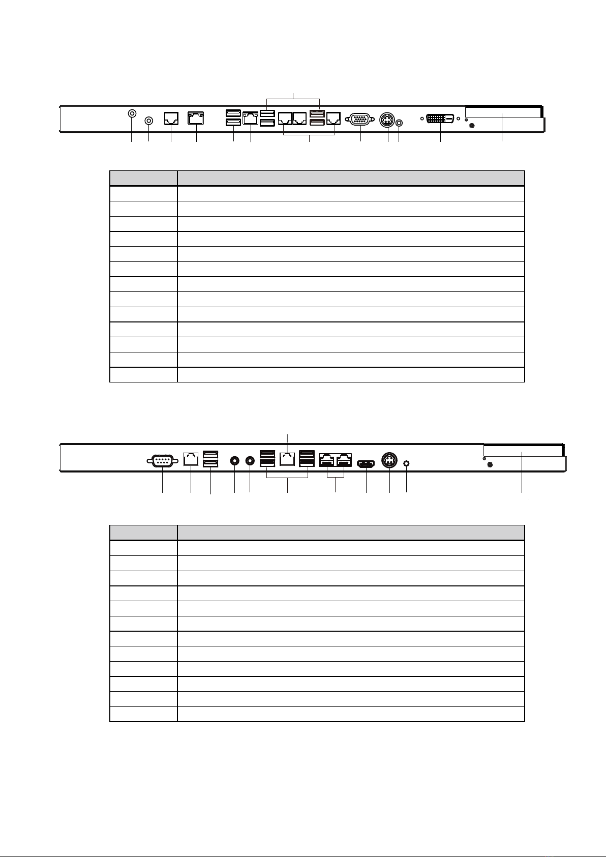
Item No. Description
a Mic in
b Line out
c COM4
d 2nd LAN
e USB 2.0(x4)
f COM port 1, 2, 3 (from left to right)
gVGA
h DC in
i Power button
j DVI-D
k HDD slot
l LAN
m USB 3.0(x2)
*The location of the DVI port for K757 IO bracket is displayed as the red circle marked
in the above figure.
Item No. Description
a Mic in
b Line out
c COM4
d 2nd LAN
e USB 2.0(x4)
f COM port 1, 2, 3 (from left to right)
gVGA
h DC in
i Power button
j DVI-D (option)
k HDD slot
l LAN
m USB 3.0 (x1)
abcdefghijk
lm
2-3. I/O view
3040 Motherboard
4040 Motherboard
5
5040 Motherboard
bcde
f
gh
ijk
m
l
a
Item No. Description
a Mic in
b Line out
c COM4
d 2nd LAN
e USB 2.0(x2)
f LAN
g COM port 1, 2, 3 (from left to right)
hVGA
i DC in
j Power button
k DVI-D
l HDD slot
m USB 3.0(x4)
5040 Motherboard
l
k
bcdefghij
a
Item No. Description
aVGA
b 2nd LAN
c USB 2.0(x2)
d Mic in
e Line out
f USB 3.0(x4)
g COM port 1, 2 (from left to right)
h HDMI
i DC in
j Power button
k HDD slot
l LAN

6
2-4. Dimensions
2-4-1. 15.6" System
2-4-2. 18.5" System
2-4-3. 21.5" System
48mm
464mm
284mm
48mm
536mm
328mm
48mm
396mm
245mm
7
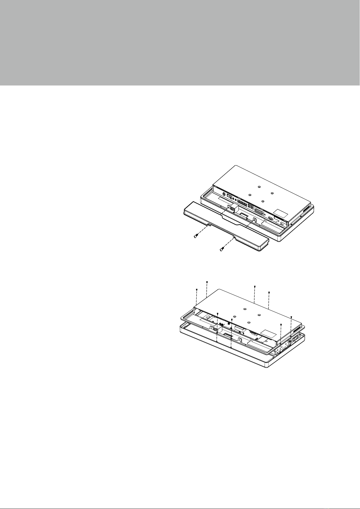
3. System Assembly
3-1. Open the Chassis Cover
The motherboard and RAM module can be replaced by opening the chassis
cover, which is located on the back side of the system. Please follow the steps
below to open the chassis cover.
1. Turn to the back side of the sys-
tem and loosen the screws (x2) to
release the cable cover first.
2. Loosen the screws (x8) to open
the back cover of the system.
8
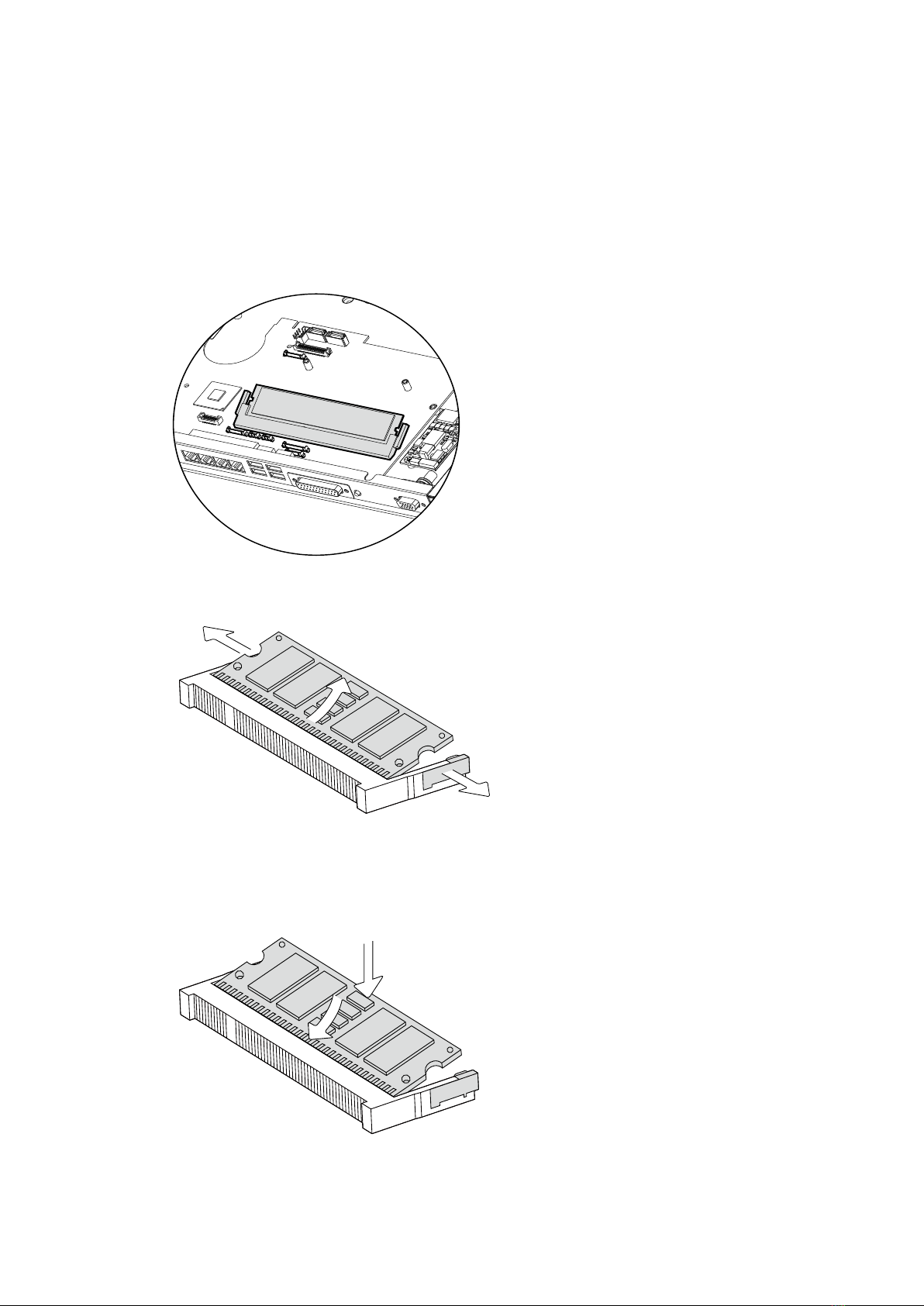
Installing a RAM moudle
3. Slide the memory module into the memory slot and press down until the
ejector clips snaps in place.
3-2. RAM Module Replacement
To remove and replace the RAM module, please open the chassis cover firstly
as steps dscribed in chapter 3-1.
Removing a RAM module
1. Find the memory slot at the right side of the motherboard.
2. Flip the ejector clips outwards to remove the memory module from the memory
slot.
9
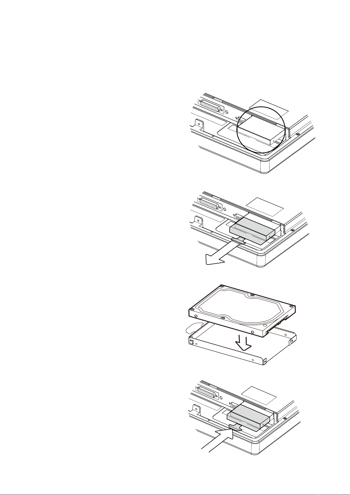
3-3. HDD Replacement
To remove and replace the HDD, please open the cable cover rstly as stpes dscribed
in chapter 3-1-1.
1. Find the HDD located at the right
side.
2. Pull the HDD tray from the system.
For easier removal pull the plastic
sheet (see picture) at the same
time.
3. Attach the HDD to the HDD tray and
slide it into the slot until it snaps in
place.
* Please note the top of the HDD
should be on the upper side.

10
4. Specication
Model Name TP-3040
Mainboard 3040
CPU
Intel Haswell CPU, LGA 1150pins, 22nm
i7-4770TE 2.3G(Turbo 3.3G), LLC 8M, 45W
i5-4570TE 2.7G(Turbo 3.3G), LLC 4M, 35W
i3-4330TE 2.4G, LLC 3M, 35W
Pentium G3320TE 2.3G, LLC 3M, 35W
Celeron G1820TE 2.2G, LLC 2M, 35W
Chipset Intel Lynx Point PCH Q87(AMT technology)
System Memory S.O.DIMM x1, FSB 1333/1600MHz, default 2G, max. 8G
Graphic Memory IIntel HD Graphics/HD Graphics 4600, integrated in CPU, DX11.1
LAN controller (Giga LAN) Intel I218LM (Phy), 2nd LAN Realtek 8111E (F40 board)
Audio controller Realtek ALC662VDO-GR
Super I/O controller Winbond W83627UHG
LVDS controller NXP PTN3460
BIOS Phoenix UEFI
Touch controller Elo coach V (USB)
TPM controller NUVOTON TPM NPCT 420
LCD/Touch Panel
LCD Size 15.6" LED LCD 18.5" LED LCD 21.5" LED LCD
Brightness 220 nits 250 nits
Maximal Resolution 1366 x 768 1920 x 1080
Touch Screen Type True at resistive touch / True at projected capacitive touch
Storage
HDD 2.5" Slim HDD bay, SATA HDD
Flash Memory SATA SSD Flash memory card 8G/16G/32G/64G (option)
Peripherals
Web Cam (Build-in) 2M Web Cam
MSR-right side(Optional) 3 Track(USB)
WiFi (Optional) 802.11 b/g/n WLAN card
Device Box(Optional) Smart IC card Reader/Scanner/Function Key Pad/Line Out/Mic In
Expansion
Mini PCI-E Socket 2 (1 x MB, 1 x F40)
External I/O Ports
USB3.0 2 x USB type A
USB2.0 4 x USB Type A
Serial / COM 3 x RJ48 (0V/5V/12V default BIOS setting 0V), 1 x RS-232/422
without power
Parallel N/A
LAN (10/100/1000) 2 x RJ-45
VGA 1 x DB 15 female
Audio Jack 1 x Mic-in, 1 x Line-out
DC Jack 1 x Latch type (4pin)
e-SATA Blind Hole
Power Button 1
DVI-D 1

11
Model Name TP-3040
Mainboard 3040
Thermal Solution
Thermal Solution 1 x Fan 2 x Fan
Audio
Speaker 2 x 2W
Environment
EMC & Safety FCC/CE Class A/LVD/EN 60601-1-2
Operating Temperature 0°C ~ 35°C (32°F ~ 95°F)
Storage Temperature -20° ~ 60°C (-4°F ~ 140°F)
Humidity 25% - 85% RH non-condensing
Dust & Water Proof IP 54 (front panel)
Dimensions
(W x D x H) 396 x 245 x 48 mm 464 x 284 x 48 mm 536 x 328 x 48 mm
Weight (N.W./G.W.) 4.5kg/5.5kg 6.8kg/7.8kg 8kg /9kg
Mounting 75mm x 75mm Standard VESA / Panel Mount
OS Support Windows 7, POSReady 7, Windows 8.1, Linux, Windows 10 IOT (64-bit)
* This specication is subject to change without prior notice.
This manual suits for next models
5
Table of contents
Other Teguar Touch Panel manuals


