TEK Biomasse AVALON User manual

AVALON
Pellet canalizable stove
A STOVE, A WORLD OF OPTIONS
Painel CP115
2Ways2+
Instruction manual
TEK Biomasse®2022 TMNG01
EN 20220919

1
Index
1. General Considerations .............................. 2
1.1. Symbology ........................................ 2
1.2. Use................................................... 2
1.3. Packaging of documentation ................. 2
2. Security warnings...................................... 2
2.1. Installer and Maintenance Technician..... 2
2.2. User ................................................. 3
3. Legal guarantee ........................................ 4
4. Replacement parts .................................... 4
5. Fuel ........................................................ 5
5.1. Fuel characteristics ............................. 5
5.2. Pellet storage ..................................... 6
6. Unloading and transport ............................. 6
7. Installation............................................... 6
7.1. Leveling of the stove ........................... 6
7.2. Installation constraints ........................ 6
7.3. Stove installation location .................... 6
7.4. Air intake .......................................... 7
7.5. Smoke evacuation duct ....................... 8
7.5.1. Basic requirements........................ 8
7.6. Piped air installation............................ 9
7.6.1. Thermal discharge device ............... 9
7.7. Electrical installation ..........................10
7.8. Installation test .................................10
7.9. Maintenance .....................................10
7.10. Other information ..............................10
7.10.1. Calculation of thermal power and
average hourly consumption ......................10
8. Use of the stove.......................................10
8.1. Useful information .............................10
8.2. Lighting............................................11
8.3. Stop ................................................11
8.4. Unplug the device from the mains ........11
8.5. Remote command..............................11
8.6. Technical Board .................................11
9. Control panel functions .............................12
9.1. Panel CP115......................................12
9.2. Led..................................................12
9.3. Messages .........................................13
9.4. State ............................................... 13
9.5. User Menu 1 ..................................... 14
9.7. User Menu 2 ..................................... 15
10. 2Ways2+ Remote Command ..................... 19
10.1. The screen ....................................... 19
10.2. Control panel .................................... 20
10.2.1. The keys .................................... 20
10.2.2. Menu ......................................... 21
10.2.3. Modify room temperature ............. 21
10.2.4. User menu.................................. 22
10.3. Chrono Menu .................................... 25
10.3.1. Modality ..................................... 25
10.3.2. Time schedule ............................. 25
11. Installing and configuring the 4Heat App ..... 27
11.1. System architecture........................... 27
11.2. Local call and remote connection ......... 27
11.3. Keys and LEDs on 4Heat modules ........ 28
11.4. Installation ....................................... 28
11.5. New 4HEAT module configuration ........ 29
11.6. Connection to 4HEATModule................ 31
11.7. App management .............................. 31
12. Maintenance............................................ 32
12.1. Security measures............................. 32
12.2. Maintenance to be carried out by the user
32
12.2.1. Daily cleaning ............................. 32
12.2.2. Weekly cleaning .......................... 32
12.2.3. Semi-annual cleaning ................... 34
12.3. Complete cleaning ............................. 34
12.3.1. Chimney cleaning ........................ 35
12.3.2. Door check ................................. 35
12.4. Exterior cleaning ............................... 35
12.5. End of season maintenance................. 35
12.6. Hydraulic installation maintenance ....... 35
12.7. Control and maintenance program ....... 36
13. Error codes ............................................. 37
14. Electric scheme ....................................... 40
15. Dimensions of connections ........................ 41
16. Models and technical characteristics............ 42

2
1. GENERAL CONSIDERATIONS
TEK Biomasse ® is a registered trademark, whose
air conditioning equipment is manufactured by
Vitor Monteiro Lda. and tested in accordance with
European reference safety standards.
1.1. Symbology
The following graphic symbols are used in this
manual:
- Tips and useful information,
- Danger, important information to avoid
accidents.
Attention: the symbols indicate important
information in order to make the manual more
lucid. However, this does not relieve the user of
the obligation to comply with requirements that
are not marked with a graphic symbol.
This manual is divided into two parts: one for the
user and one for the installer. Both parts contain
important and significant information for safety
issues, therefore, the user should read both parts
of the manual. We are not responsible for any
damage caused by failure to follow these
instructions.
1.2. Use
This equipment is a stove intended for domestic
heating and is reserved for indoor installation. It
must not be operated by anyone unfamiliar with
this manual as well as by children, the elderly and
others whose physical, mental and intellectual
capacities are impaired.
Failure to observe these rules can cause property
damage, threat to human life and health and
domestic animals.
1.3. Packaging of documentation
This manual, as well as any other applicable
documentation, must be stored diligently so that
it is available at all times. In case of moving or
selling the equipment, the documentation must
be attached and forwarded to the new
user/owner.
2. SECURITY WARNINGS
The instructions contained in this manual must be
followed, both by the Technician (Installer,
Maintenance) and by the User. Some of the
warnings, if not followed, void the warranty
contract.
2.1. Installer and Maintenance
Technician
The installation of the stove is reserved
exclusively for specialized technicians.
The responsibility for installing the equipment
cannot be considered the responsibility of Vitor
Monteiro, Lda.
In case of need for works at the installation site
of the stove, these are the responsibility of the
user and whose expense falls on the same, before
being carried out, must be approved by the user.
The technical responsibility for the installation
rests with the installer, who is asked to carry out
the chimney and air intake checks and carry out
the proposed installation solutions correctly.
Installation of the equipment must comply with
all national and European regulations, standards
and laws.
The equipment must be installed on a surface
capable of supporting its weight.
Confirm that the chimney design and air intake
are in accordance with the installed equipment.
3
Do not make electrical connections with
temporary or non-insulated cables.
Check that the equipment ground connection is
effective.
Before starting the unpacking and assembling or
disassembling of the stove, the Technician must
take the safety measures prescribed by law, with
special attention to those mentioned below:
•Ensure that the equipment installation site
complies with all national and European
regulations/laws;
•Ensure the use of all personal protective
equipment;
•Make sure that the workplace is in a safe
condition to perform the installation;
•To perform the installation, the installer
must be in full psychophysical conditions;
•No work should be carried out under
adverse conditions.
During maintenance operations, the
technician must carefully observe the following
instructions:
•Maintenance should only be carried out by
qualified personnel, at least once a year;
•Check that the stove is cold before
carrying out any type of work;
•Disconnect the equipment from the
electrical current before starting
maintenance work;
•Use personal protective equipment and/or
other means of protection;
•All electrical and mechanical components
guarantee the correct functioning of the
stove, so they can only be replaced by
original components purchased from the
brand's technical assistance;
•The equipment must be taken out of
service if any safety component is
defective or out of calibration.
On water models, the installer must inform
the user of the following:
•In case of water leaks, it is necessary to
turn off the water supply and immediately
notify technical support.
•System pressure operation must be
checked periodically.
2.2. User
Before using for the first time, the user must read
this manual in its entirety and bear in mind the
following:
•Immediately disconnect the equipment
from the power supply in the event of a
breakdown or malfunction;
•The power plug must be easily accessible;
•When in normal operation, never
disconnect the appliance from the
electrical supply;
•If you are not going to use the stove for a
long period of time, disconnect the power
and remove the pellets from the hopper;
•After a more or less prolonged downtime,
the stove should be regularly serviced;
•The stove must not be switched on without
having carried out the daily maintenance
and/or inspection as referred to in point
12.2.1 Daily ;
•This stove does not work with wood, use
only 100% wood pellets as fuel according
to the manufacturer's recommendations.
See point 5.1 Fuel characteristics;
•This equipment is not an incinerator
do not use foreign substances as fuel;
•It is forbidden to operate the equipment
with the door open or with broken glass,
or even to open the door with the
equipment in operation;
•The equipment lights up automatically, so
you should not use any product to light the
stove, especially flammable liquids;

4
•When in operation, the stove has very hot
surfaces, so you should not approach or
touch them, with special emphasis on the
glass and door, chimney, among other
elements;
•The glove supplied with the appliance
must be used to handle the appliance's
components.
•It is forbidden to place clothes to dry or
other objects on the equipment or in its
proximity that impede the free circulation
of air;
•Clean the equipment only when it is
completely cold and turned off;
•The ash compartment must not be opened
while the stove is operating. Wait for it to
stop and cool down completely to clean
the ash.
Children: - Do not let children play near
the stove or touch it.
•The equipment extinguishes by itself, so
do not use water or to put out the fire in
the brazier;
•Periodically clean the chimney according
to the instructions in point 12.3.1-
Chimney cleaning.
3. LEGAL GUARANTEE
The manufacturer guarantees the product, with
the exception of elements subject to normal use,
listed below, in compliance with Directive
CEE199/44/EC from the date of purchase attested
by:
•Invoice with date of purchase;
•Installation compliance certificate issued
by the installer.
Exclusions:
The warranty does not cover damage or
malfunctions arising from the following causes:
•Damage caused during transport or
handling;
•Failure of components resulting from
improper use or negligence, lack of
maintenance, installation in violation of
current regulations and laws.
•Use of poor quality pellets or any other
similar product in disregard of the
provisions of Point 5;
•Malfunctions resulting from poorly
executed repair attempts;
•Forced use of equipment after failure
alarm;
•Chimney malfunction;
•Damage caused by tampering with the
equipment, atmospheric agents, natural
disasters, vandalism, electric shocks,
fires, failures resulting from the electrical
or hydraulic network.
The following items subject to normal wear and
tear are not covered by the warranty:
•Vermiculite;
•Door glass;
•Sealing packages;
•Painting;
•The brazier (burner) in cast iron;
•The ignition resistance.
4. REPLACEMENT PARTS
In maintenance operations, only original parts
may be used. For this purpose, consult the
technical assistance service.
Do not wait until the complete failure of the
components, therefore, it is recommended that
they be replaced when necessary in the periodic
maintenance actions.
During the first lighting of your equipment,
it is possible that some odors may be
released resulting from the natural drying of
paints and putties. Avoid prolonged
exposure to these odors. It is advised:
•Air the space;
•Do not touch surfaces when they are
hot to avoid damaging the coating.

5
The manufacturer will guarantee replacement
parts for the legally prescribed period.
5. FUEL
100% pressed pine wood pellets certified
according to the EN PLUS A1 standard are the
only fuel allowed for use in this boiler.
The pellets used must be certified and in
accordance with EN Plus 14961 or 17225-2.
5.1. Fuel characteristics
Pellets are produced by pressing wood chips and
sawdust. They are obtained without the addition
of any foreign substance, such as adhesives,
lacquers or synthetic substances.
Pressing through a matrix of holes and the heat
produced by friction and pressure, activates
natural wood binders that in this way ensure the
shape of the pellets even without the addition of
binders.
The production and consumption of pellets is
based on the rational use of renewable energy
with zero impact on the CO 2 cycle, which respects
environmental protection standards.
This is the only fuel indicated for this equipment.
Yield and power vary depending on the quality of
pellets used.
For correct operation you must use pellets
according to the characteristics below.
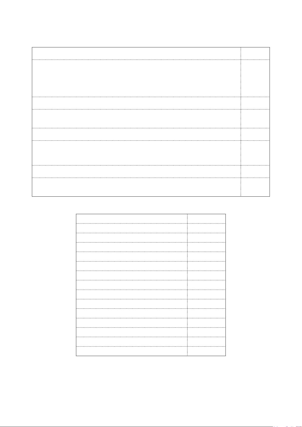
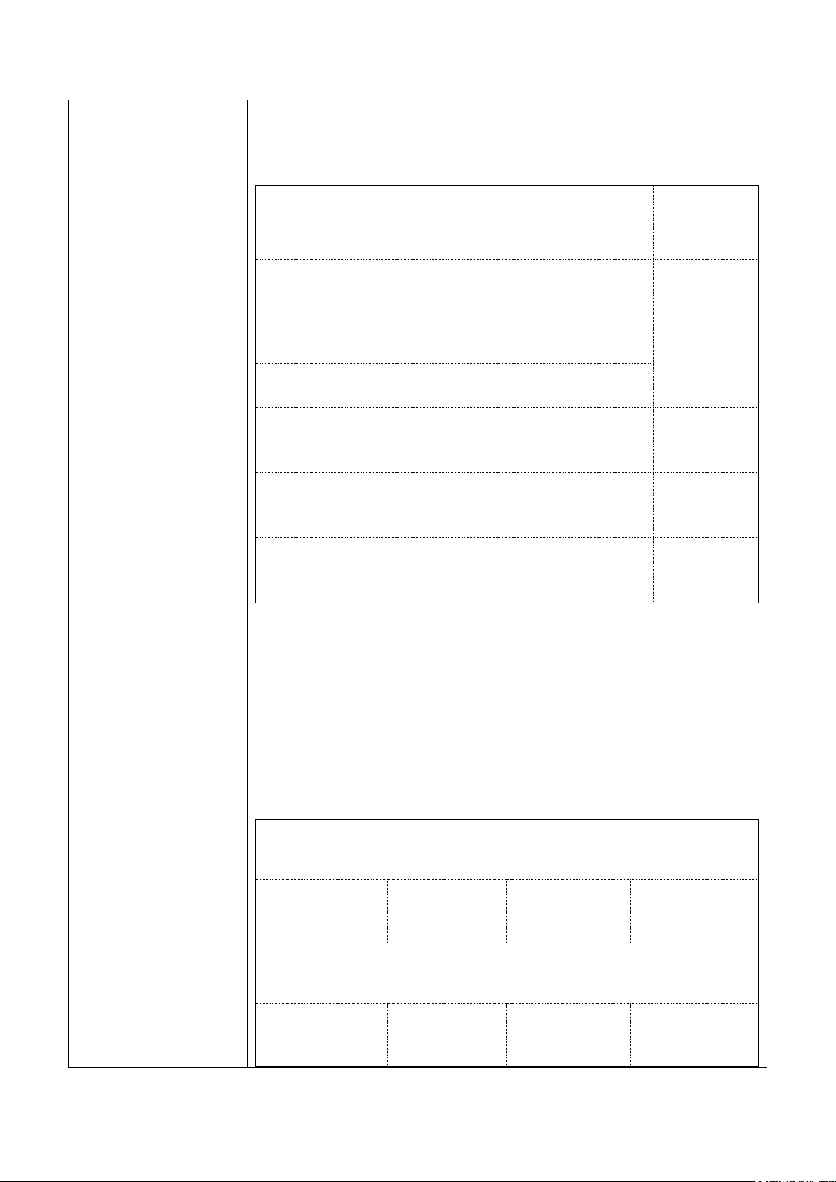
Technical Fuel Information (Pellets)
Diameter
6mm
Length
10 to30 mm
Density in the bag
min. 650 kg/m 3
Humidity
Max. 10%
Max. from the ashes
Max. 1.5%
Max. from the dust
Max. 2.3%
Calorific value of various fuels:
Wood Pellets
4.9 kWh /kg
wood chip
± 850kW.h/m 3
soft woods
±1500 kW.h /m 3
hard woods
±2000 kW.h /m 3
Coal
7 kW.h /kg
Naphtha
7.5 - 8 kW.h /kg
Natural gas
9.5 - 10.2 kW.h /m 3
liquid gas
12.8 kWh /kg
The stove is equipped with a hopper (deposit) for
pellets with a capacity for 1 bag of 15 kg.
The supply of pellets must only be carried out
through the door that gives access to the cargo
compartment located at the top. This should only
be opened to load the pellets and only when it is
not in operation, it is not advisable to supply
pellets with the stove in operation.
Figure 1- Cargo cover

6
5.2. Pellet storage
The functioning of the stove depends largely on
the quality and conservation conditions of the
pellets, for this reason they must be stored in a
dry place where they do not reach too low
temperatures.
Poor packaging of the pellets can lead to the
breakdown of particles and create sawdust.
Sawdust is responsible for the malfunction of the
power system and can block it.
We recommend storing a few bags of pellets
in a warm and dry place, because cold pellets
(5º.C) and/or damp reduce the calorific value of
the fuel and cause more dirt, requiring more
rigorous maintenance and cleaning.
6. UNLOADING AND TRANSPORT
The stove must be transported vertically without
rocking during the entire transport process.
The stove's brazier as well as other components
can come loose causing damage to the product.
The stove's packaging must not be impacted or
hit by other objects or equipment, under penalty
of causing damage that will compromise the
stove's future operation.
Make sure that the means of transport used has
a capacity greater than the weight of the stove.
7. INSTALLATION
To obtain the best performance from the stove
and uniform heating of the room, you must
comply with some essential rules.
Improper installation will compromise the safety
and proper functioning of the stove.
When installing the equipment, all national and
local regulations, as well as European standards,
must be observed.
7.1. Leveling of the stove
The stove must be leveled using a bubble water
level and using the rubber adjustment feet.
7.2. Installation constraints
It must be safeguarded that no mechanical
exhaust fans or collective ventilation ducts are
installed at the installation site.
In any case, it must be safeguarded that the
installation site is not in a depression, preventing
the simultaneous operation of the systems
mentioned above, since this will compromise the
normal functioning of the stove and possible
release of dangerous fumes. Check point 16
Models and technical characteristicsfor more
information.
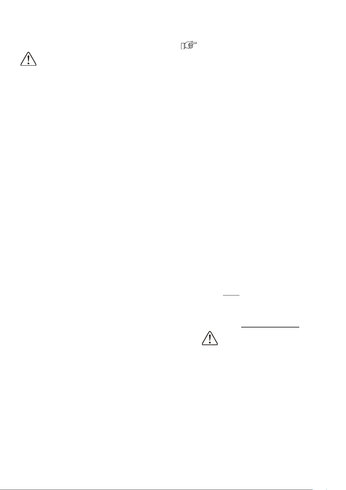
7.3. Stove installation location
The following figure indicates the minimum
distances (in centimeters) from combustible
surfaces that must be observed when installing
the stove. In the case of non-flammable
walls/objects these distances can be reduced by
half.
Figure 2- Minimum dimensions to respect in relation to
adjacent surfaces
The floor protection to support the stove must
guarantee fire resistance in accordance with
European standards. Never place the stove
directly on wood, carpet or other combustible
materials.
7
During installation, structures, coverings, beams,
etc., must be protected from combustible or
flammable material and which are exposed to
excessive heat from both the stove and the
chimney, particularly when crossing partitions
and false ceilings. In these cases, appropriate
thermal insulation should be used, namely
vermiculite.
Check point 16- Models and technical
characteristicsfor more information.
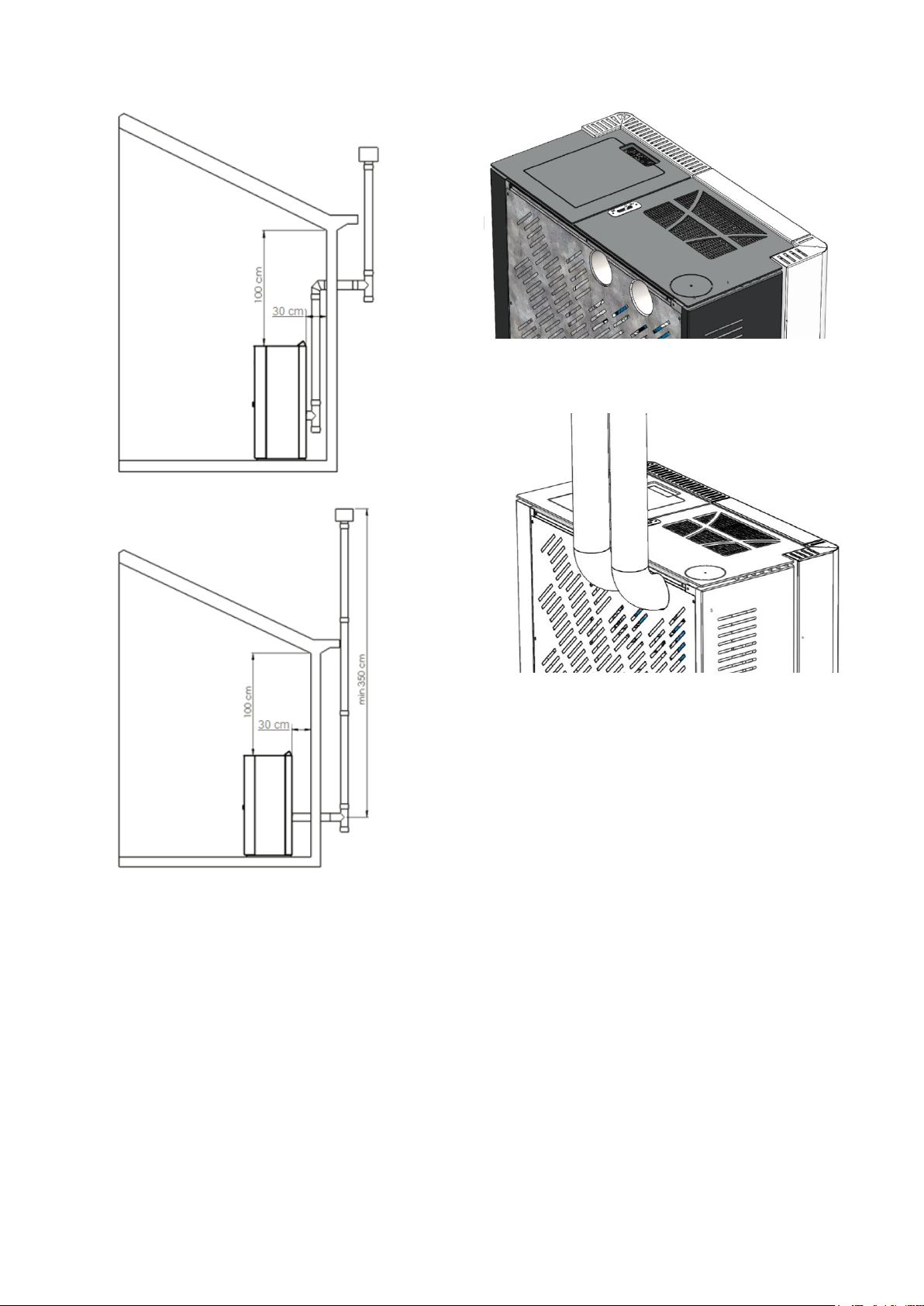
Figure 3- Minimum dimensions to respect the envelope and
minimum height of the chimney
The manufacturer will not be responsible for
changes in the properties of the materials
surrounding the stove and chimney.
7.4. Air intake
The heat generated by the stove results from the
heat produced by the chemical reaction of
combustion of the pellets in the combustion
chamber.
For this combustion to occur under the best
conditions, it is necessary to safeguard the
correct amount of oxidizing agent (oxygen
present in the air).
During operation, the stove absorbs an amount of
air from the place where it is located, which
enters the combustion chamber through an air
inlet located at the back of the stove, which can
be channeled to the outside.
You must not use bends or tubes with a section
smaller than 60mm, nor a maximum length
greater than 800mm.
You must also safeguard that this admission will
never be obstructed from the outside and that it
is at least 20 cm from the ground.
Outside, you should put protection against rain
and wind.
Safeguard the requirements and relative to
ventilation and air supply referred to in point 7.2-
Installation constraints.
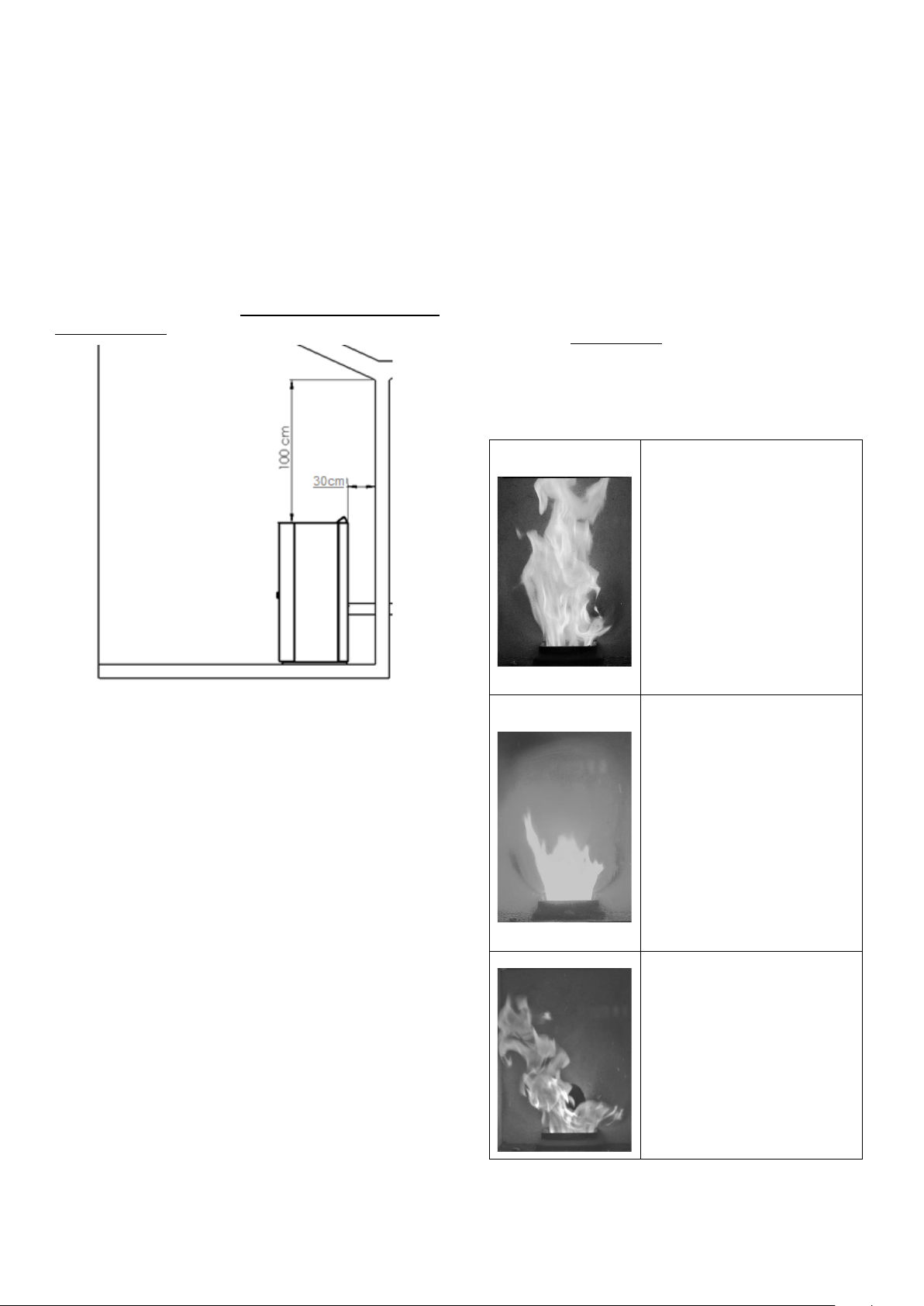
In the figure below you will find several examples
that will help you to verify the stability and
correction of the flame.
Correct combustion
Bright flame with light
yellow color and minimum
amount of pellets in the
brazier
Incorrect combustion
Flame too bright too
much oxidizer.
Too many glowing pellets
come out of the brazier.
Correct the amount of air
(from 0 to +5) correct the
feeder if necessary (from
0 to -5).
If not, contact technical
support.
Incorrect combustion
Flame too dark yellow,
wobbling, with too many
unburned pellets in the
brazier.
Check that the door or
ash bin is closed.
Otherwise, correct the
amount of air (from 0 to

8
+5) correct the feeder if
necessary (from 0 to -5).
If not, contact technical
support.
7.5. Smoke evacuation duct
The smoke discharge from the stove is with
positive pressure in relation to the surrounding
environment, so it is essential to guarantee the
tightness of the different joints of the chimney.
The smoke evacuation duct must be independent
from other equipment.
To guarantee the correct extraction of the smoke,
it is mandatory that the first section of the
chimney be vertical with a height of not less than
1.5 meters.
The horizontal sections must not be longer than
1.5 meters with a slope of at least 5%.
The chimney outlet must comply with EN 1856-2
for built-in masonry chimneys and EN 1856-1 for
insulated outdoor chimneys. It must be in 0.5mm
thick 316 stainless steel with dimensions
respecting what is indicated in the equipment
characteristics, regarding the smoke outlet.
The smoke duct must have a diameter of 80 mm,
with male/female joints fitted with a high-
temperature silicone gasket (>200ºC) with
inverted installation (male downwards) to
prevent condensation from flowing out of the
chimney.
For chimneys over 5 meters high, their section
must change to a diameter of 100 mm after 5
meters. The dimensioning of the smoke duct must
be done considering 0 P a.
The piping used outdoors must be in double-
walled stainless steel, in order to avoid
condensation and corrosion of the same, resulting
from the thermal shock.
It is forbidden to install dampers, butterflies or
valves that strangle the chimney's draft capacity.
The fume exhaust capacity depends on several
factors, including the height of the chimney.
Depending on these factors, it may be necessary
to make adjustments to the stove's operating
parameters. Excess draft when it is not possible
to correct it by changing parameters such as air
intake and pellet loading, it will imply the
installation of an air intake valve to the chimney.
If necessary, contact the technical assistance
service.
7.5.1. Basic requirements
Below are some proposals for the execution of a
chimney, which should be understood as
schemes, not replacing a specialty project.
Figure 4- Example of vertical installation
9
Figure 5- Example of installation with wall outlet
Figure 6- Example of installation from the outside
7.6. Piped air installation
(ducted hot air stoves)
The stove has two 80 diameter hot air outlets at
the rear, intended for channeling air to other
rooms in the house through appropriate piping.
7.6.1. Thermal discharge device
The system is protected against boiler
overheating. This protection is based on two
phases:
1st stage, the working temperature is limited by
the electronic controller, ensuring that the boiler
temperature does not exceed the value defined in
the set-point (Maximum factory limit Max 75ºC).
The equipment has two safety thermostats
connected in series with the supply device, one
installed in the hopper, limiting its temperature to
85ºC and another in the boiler, limiting its
temperature to 95ºC. If the boiler exceeds the
activation value of any of these thermostats, they
cut the power supply to the power supply device,
triggering an audible and visual alarm on the
electronic panel and activating the circulation
pump to dissipate excess heat. It is still turning
on the exhaust fan at maximum speed to cool the
boiler body and extinguish the flame. Also, if the
maximum pressure is exceeded, the system will
act as previously defined, namely blocking the
supply and extinguishing the flame.

10
7.7. Electrical installation
Installation must be carried
out by qualified personnel
according to EN 10683.
Ensure that the electrical
installation has ground
connection.
With the switch off, connect the cable to the
wall socket and plug.
Turn on the switch to
electrically power the stove.
For more information, see
point 14- Electric schemeof
this manual.
7.8. Installation
test
8.2 - Lightingand 8.3- Stop must be taken into
account.
7.9. Maintenance
When installing the equipment, the space
required for maintenance and cleaning of the
equipment and respective connection and smoke
evacuation ducts, as well as the respective
hydraulic networks (water models) must be taken
into account.
For more detailed information, see point 12-
Maintenance.
7.10. Other information
7.10.1. Calculation of thermal power
and average hourly
consumption
The calculation of the thermal power required for
heating a given space can be performed using a
very simple method, since, on average, the
heating power required for a properly insulated
room is approximately 40 W/m 3.
If we want to heat a space with 100m 3 then we
have:
100m 3 x40W/m 3 = 4000W, that is, 4 kW.
For this main heating requirement, a 6.5 kW
appliance will therefore suffice.
8. USE OF THE STOVE
8.1. Useful information
Fuel used: see point 5- Fuel.
In order to avoid the risk of fire, you must comply
with the instructions contained in point 2.2User-
Security warnings, with special emphasis on the
following aspects:
•It is forbidden to place clothes to dry
or other objects on the equipment or in its
proximity that impede the free circulation
of air;
•Clean the equipment only when it is
completely cold and turned off;
•The ash compartment must not be
opened while the stove is operating. Wait
for it to stop and cool down completely to
clean the ash.
Simultaneous use with other ventilation systems:
see point 7.2- Installation constraints.
Safeguard the safety distance from combustible
materials: see point 7.3Stove .
Air supply and smoke evacuation: see points 7.4-
Air intakeand 7.5- Smoke evacuation duct.
If a fire occurs in the equipment or chimney, you
must:
•Immediately turn off the equipment;
•Do not open any equipment door;
•Do not use water to put out the fire;
•Putting out the fire using a CO2
extinguisher
•Request the intervention of the fire
department.
See the terms of legal warranty and replacement
parts in the points: 3- Legal guaranteeand Erro!
A origem da referência não foi encontrada.-
Erro! A origem da referência não foi
encontrada..

11
8.2. Lighting
The stove is switched on by pressing the ON/OFF
key for 3s.
The word “Activation” will appear on the display
until ignition is complete. This process will take
an average of 5 to 12 min. Once completed, the
ignition will move to a flame stabilization phase
and, finally, it will enter the previously selected
power level or what was in use when the stove
was last turned off.
User can select 5 power levels.
8.3. Stop
Stopping is carried out by pressing the ON/OFF
key for 3s. The word “Deactivation” will appear on
the display. The feeding of pellets will be stopped,
and the room and smoke extraction fans will be
activated to guarantee the complete burning of all
the material until the temperature of the stove is
reduced to 40ºC.
8.4. Unplug the device from the
mains
Attention! Ensure that the device is not
disconnected from the power supply when it is in
operation. This process requires that the device is
not performing any operations and that the
display shows “OFF”.
8.5. Remote command
Remote command instructions are executed only
when the standby screen - OFF (see Control
Panel) or automatic mode (see Figure 13)
appears on the display.
The command allows the following operations:
•ON/OFF
•Ambient fan speed
•Power level
8.6. Technical Board
For information on the device's performance values
and the CO emission value, see point 16Models and
technical characteristics.
12
9. CONTROL PANEL FUNCTIONS
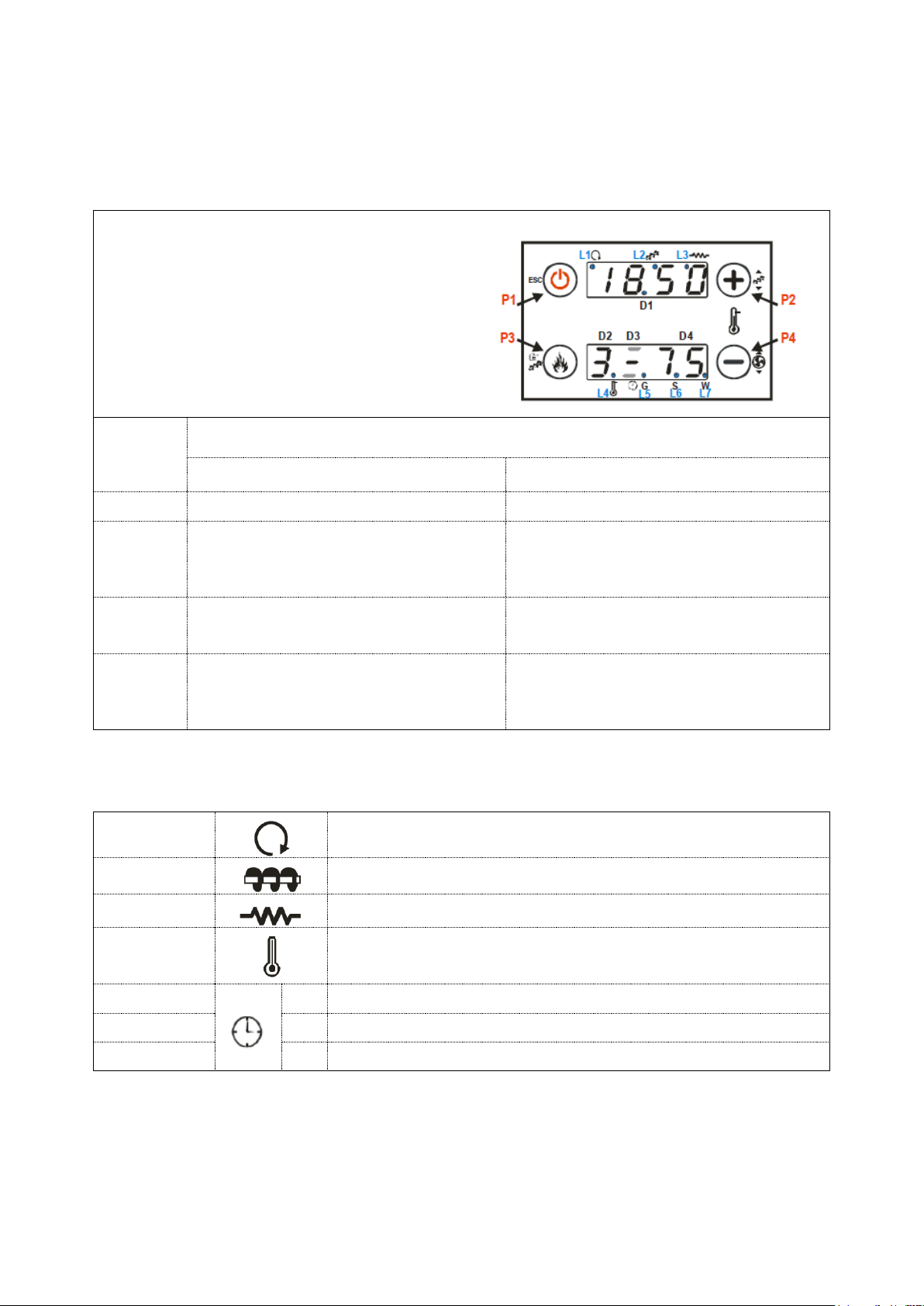
9.1. Panel CP115
Values shown on the panel
Display D1: time, system status, error, menu,
submenu, parameter value;
Display D2: power, parameter code;
D3 display: recipe;
Display D4: main temperature, parameter
code.
Key
Functions
1 Click
Prolonged pressure (3s)
P1
View / Exit menu (Esc)
Ignition / Extinguishing
P2
Thermostat->modify required
temperature (+)
increase data
Pellet loading correction
After 3s press (+) or (-) and confirm
(P3)
P3
Modify combustion power
confirm data
Manual pellet loading
P4
Thermostat-> modify required
temperature (-)
decrease data
Combustion fan speed correction
After 3s press (+) or (-) and confirm
(P3)
9.2. Led
L1
Led On: Heating fan on
L2
LED ON: Power on
L3
Led On: Ignition resistor on
L4
Led On: Thermostat temperature reached
L5
G
Led On: Selected daily program (Giorno)
L6
S
Led On: Selected weekly program (Setimana)
L7
W
Led On: Selected weekend program (Weekend)
13
9.3. Messages
Description of messages
Code
Viewing the status of the temperature probes. The message displayed in the
Check-Up indicates that the temperature reading on one or more probes is equal
to the minimum (0 °C) or maximum value (depends on the probe considered).
Check that the probes are not open (0 °C) or that they are short-circuited
(maximum value of the temperature scale).
probe
Room temperature above 50 °C
hi
This message notifies you that the planned hours of operation (parameter T67)
are reached. Proceed to cleaning. To clear the warning see Reset Clear (rCLr)
CLr
Open door. You must close the door!
Port
The message appears if the system is instructed to switch off when it is still on,
via an external device: the system will only stop when it switches to operating
mode.
OFF
del
Automatic periodic cleaning running
PCLr
Message displayed when there is a request for domestic hot water (flow switch
contact closed). Appears only for installations with DHW
FL
9.4. State
State
Code
OFF
-
Verification
Check
Ignition-Preheating Phase
on 1
Ignition-Pre-Charge Phase
on 2
Ignition-Fixed Phase
on 3
Ignition-Variable Phase
on 4
Stabilization
on 5
Operation
-
Modulation
mod
Wait
STBY
Safety
SAF
Extinction
OFF
Block
Alt
Recover the ignition
rec

14
9.5. User Menu 1
Views
tF: Smoke temperature [°C]
tA: Room temperature [°C]
tr: Remote room temperature [°C]
FL: Primary airflow speed
UF: Combustion fan speed / Voltage [RPM / Volt]
Co: Speed / Auger ON time [RPM / sec ]
St: Time remaining for maintenance 1 [h]
St2: Time remaining for maintenance 2 [h]
FC: Firmware Code and Revision
Combustion Power
Configuration
Click the P3 button: the D2 display flashes. With another click of
the same button, the power is changed. Eg: 1–2–3–4–5 –A (A =
automatic combustion). After 5 seconds, the new value is saved
and the display is shown as normal.
Manual pellet
loading
A long press on the P3 button activates the manual loading of
pellets with continuous activation of the worm gearmotor. The
bottom display shows the word LoAd, the top display shows the
elapsed loading time. To stop charging, press any button.
Charging stops automatically after 300 seconds. Enabled only if
A48 = 0.
Pellet loading
correction
A long press on the P2 button activates this function (doing it twice
enters the modification mode). The bottom display shows PELL,
the top shows the value. With the P2 / P4 buttons the value is
increased or decreased; the factory value is "0". After 5 seconds,
the new value is saved and the display is shown as normal.
Enabled only if A64 = 1.
Combustion fan
correction
Long press of the P4 button activates this function (you need to
do this twice to enter modification mode). The lower display shows
Vent, the upper one shows the value. With the P2 / P4 buttons
the value is increased or decreased; the factory value is "0". After
5 seconds, the new value is saved and the display appears as
normal.
Enabled only if A64 = 1.
Thermostat setup
The current thermostat value is shown on the lower display; if P69
is different from 0 and the airflow is controlled by remote control,
thermostat Th53 will be displayed.

15
9.7. User Menu 2
Access to the menu is done by pressing P3 and P4 at the same time
Heating power (Air)
This menu allows you to change the heating power, if A04 = 1 the menu
is not visible.
Heating
Description
1 - Level
number
Power manually set from 1 to the power level available
to the user
Self
Heating power automatically adjusted by the system
(according to the value of P06)
Ducted air heating
power (Air1)
(only on some models)
This menu allows you to change the power of the ducting fan. It is only
visible in a heating installation with 2 heating fans is present (ducted
air).
Channel air
direction selection
menu (SEL)
(only on some models)
This menu allows you to manage the position of the selector and change
the direction of the heating air flow (ducted air).
Heating
Description
LoC
Airflow in the room where the greenhouse
is located.
rEM
Airflow in the remote room
Thermostats (TerM)
This menu allows you to modify the value of the remote room
thermostat, it is visible only if A18 = 1 and a heating installation that
needs it.

16
Chrono (Cron)
This menu allows you to set the system on/off times.
Chrono has two submenus:
Chrono activation menu
This menu allows you to select the desired chrono mode. ModE appears
on the display.
MODALITY (Mode)
LED
Gior: Daily program day by day
SEtt: Weekly Mon-Sun program.
FiSE: Saturday and Sunday weekend
program
OFF: Programs disabled
- Scheduling of timetables
The word ProG appears on the display. Each program mode has 3
submenus, one for:
Daily: allows you to set 3 programs for each day of the week (Mo-
Monday, Tu-Tuesday, Ue -Wednesday, Th -Thursday, Fr-Friday, SA-
Saturday, Su - Sunday).
Week l: allows you to set 3 programs to run every day of the week
(MS).
Weekend: Allows you to set 3 programs for Monday-Friday (MF) and 3
programs for Saturday-Sunday (S S).
visualization
display
Daily Mode: Every Day (Mo,Tu,Ue,Th,Fr,Sa,Su)
m o
Weekly mode: Monday to Sunday
MS
Weekend mode:
from Monday to Friday
Saturday Sunday
MF
S S
Switch-on time indicated by the lower dash on the D2
display
1st _ _
Switch-off time indicated by the upper dash on the D2
display
1 IMo
17
Instructions
For each program it is necessary to define the start time and end time.
DESCRIPTION
display
1) Press the P2/P4 keys until the desired submenu and
press the P3 key
Giorn
2) Press the P2/P4 keys to select one of the 3 available
programs
- - - -
1IMo
3) Press the P1 key for 3 seconds
0 0. 0 0
1IMo
4) Select the call time
5) Press the P3 key until the hour or minute starts
flashing. Press the P3 key again to change between
hours and minutes and P2/P4 to change the values.
0 1.0 0
1st _ _
6) Press the P3 key to confirm values
2 1. 3 0
1I M o
7) Use the P2 key to select the switch-off time and
repeat the operations from point 5.
0 0. 0 0
1 Im o
For each time program it is possible to change the minutes in 15-minute
intervals (for example: 20:00, 20:15, 20:30, 20:45).
Only for 23:00 it is possible to increase minutes from 45 to 59, in order
to obtain a light around midnight.
Time schedule through midnight
Set to a weekday off schedule time of 11:59 pm. Set the next day's
switch-on time at 00:00, only in this way will it be possible to keep the
boiler on after midnight.
Example
Monday program
ON - League
2 2. 0 0
1st _ _
2 3. 5 9
1st _ _
OFF –Turn off
Tuesday program
ON - League
0 0. 0 0
1 I T u
0 7. 0 0
1 I T u
OFF - Turn off

18
Watch (oroL)
This menu is for setting the time and date. The upper display shows the hour and
minutes, the lower display shows the day of the week.
DESCRIPTION
DISPLAY
Press P3 key to enter edit mode. The hour, minute and day of week
values will flash. To change the value use the P2/P4 key.
Press the P3 key to change other values.
Press P3 again to save the values.
0 7. 3 3
m o
Summer-Winter
(functional)
Menu to modify the operation of the installation according to the season.
Reset (rCLr)
Menu to reset the timeout of "System Maintenance Function". It is visible only if
T67> 0. Press P3 twice to confirm.
Technical menu (TPAr)
This menu is reserved for the technician.
The technical menu of the panel with 2Ways radio control consists only of the reset
counters and the reset service menu (tP11). All other functions are performed
directly in 2Ways.

19
10. 2WAYS2+ REMOTE COMMAND
The radio remote control thermostat manages the operation of the boiler and monitors the operating
status in real time.
The main features are:
•System remote control
•Room thermostat
•Management of operating and control parameters
Attention:
The system operates on the 868.3MHz ISM radio band.
The transmission and reception distance may be reduced in the case of electromagnetically noisy
environments: other devices such as wireless headphones, sender, toys or other devices may influence
system performance. Check for the presence of such instruments and be sure to turn them off in order
to avoid electromagnetic wave pollution. If more remote thermostats are nearby, it is necessary to
associate the remote control with each specific boiler (see settings menu).
10.1. The screen
Pressing the button turns on the screen and displays the main window.
Table of contents
Other TEK Biomasse Stove manuals


Popular Stove manuals by other brands


MCZ
MCZ RAAM COMFORT AIR 8 S2 installation guide

Percy Doughty & Co
Percy Doughty & Co FIREFOX 8 Installation and operating instructions

Next
Next 780455 Assembly instructions

United States Stove
United States Stove Fiero C9947L OWNER'S OPERATION AND INSTALLATION MANUAL

STOVES
STOVES SEC60DO Users guide & installation handbook

MHSC
MHSC Windsor WR244 owner's manual