TEKA ILLUMINATION LARGE BEACON STEM MOUNT User manual

THIS DOCUMENT CONTAINS PROPRIETARY INFORMATION OF TEKA ILLUMINATION AND ITS RECEIPT OR POSSESSION DOES NOT CONVEY ANY RIGHTS TO REPRODUCE, DISCLOSE ITS CONTENTS, OR TO MANUFACTURE, USE OR SELL ANYTHING IT MAY
DESCRIBE. REPRODUCTION, DISCLOSURE OR USE WITHOUT SPECIFIC WRITTEN AUTHORIZATION OF TEKA ILLUMINATION IS STRICTLY FORBIDDEN.
Warning Hot Surface
NEEDED
FOR
INSTALLATION:
By Others
Wear Gloves
RELEASE DATE
5-4-18
REFERENCE NUMBER
INS-2690-00
40429 Brickyard Drive • Madera, CA 93636 • USA
559.438.5800 • FAX 559.438.5900
High Voltage
5/32” & 0.050” Allen Wrench
Waterproof Wire Connectors
Phillips Screwdriver
Gloves
Small Pick Tool
Stem
Shade
Frosted
Cylinder
Lens
Cap
IMPORTANT SAFETY INFORMATION - READ, FOLLOW, AND SAVE THESE INSTALLATION INSTRUCTIONS
LARGE BEACON STEM MOUNT™ (LBS)
Rings
IMPORTANT - WEAR GLOVES TO AVOID GETTING FINGERPRINTS ON THIS PRODUCT. MANY TEKA ILLUMINATION PRODUCTS ARE DESIGNED TO NATURALLY PATINA.
OILS FROM YOUR SKIN WILL ACCELERATE THIS PROCESS WHERE TOUCHED AND ARE NEARLY IMPOSSIBLE TO REMOVE. THIS PROCESS OCCURS OVER TIME AND IS
DETERMINED BY THE INSTALLATION ENVIRONMENT.
· Suitable for wet locations
IMPORTANT LISTINGS AND CERTIFICATIONS
IMPORTANT SAFETY INFORMATION - READ, FOLLOW, AND SAVE THESE INSTALLATION INSTRUCTIONS
• Product must be installed by a qualified person in a manner
consistent with its intended use and in compliance with the
National Electrical Code, Canadian Electrical Code, and all Local and
Provincial Codes.
• Follow product label information and instructions.
• Qualified Personnel with appropriate personal protective
equipment must perform all servicing of this product.
• Before wiring to power supply and during servicing, turn off and
lock out power at fuse or circuit breaker before service.
• The use of accessory equipment not recommended by the
manufacturer or installed contrary to instructions may cause an
unsafe condition. The use of damaged components may cause an
unsafe condition and void product warranty.
IMPORTANT SAFETY INFORMATION - READ, FOLLOW, AND SAVE ALL SAFETY
AND INSTALLATION INSTRUCTIONS
• Do not block light emanating from product in whole or part, as
this may cause an unsafe condition.
• Never operate the fixture with missing or damaged lens.
Lens must be cleaned on regular basis.
• Entire fixture may become extremely hot. Do not touch hot
lens or fixture body.
• Replace LED assembly only with correct wattage and type of
power supply appropriate for LED assembly.
• All gaskets, o-rings and sealing surfaces must be kept clean
during installation and service; failure to do this may cause an
unsafe condition and void product warranty.
INSTRUCTIONS PERTAINING TO
A RISK OF FIRE, OR INJURY TO
PERSONS IMPORTANT SAFETY
INSTRUCTIONS
Lighted fixture is HOT!
WARNING - To reduce the risk of
FIRE OR INJURY TO PERSONS:
Turn off/unplug and allow to cool before replacing LED.
Fixture gets HOT quickly! Contact only switch/plug when
turning on. Do not touch hot lens, guard, or enclosure.
Keep fixture away from materials that may burn.
Do not operate the luminaire fitting with a missing or
damaged shield. Do not touch the source at any time. Use
a soft cloth or gloves. Oil from skin may cause damage.
SAVE THESE INSTRUCTIONS
Canopy
REMOTE WIRING
LED Driver
Remote driver installations require inter-connected
wiring between the LED and driver (by others). Drivers
have specific wiring requirements between these
components. Driver manufacturers regularly recommend
the following wiring details for such installations:
• Do not exceed 50 foot overall wiring distance
using 12 gauge copper wire.
Failure to comply with specific wiring
requirements will void product warranty.
DRIVER HOUSING REQUIRED
Please refer to specified remote driver housing
documentation for detailed installation instructions.
REMOTE DRIVER HOUSINGS:
PM3RM - Universal Power Module 3 Remote
PM3DRM - Universal Power Module 3 Dual Remote
RM - Remote Wall Mount
DRM - Dual Remote Wall Mount
PM2RM PM2DRM PM3RM PM3DRM
PM3RM &
PM3DRM
PM2RM PM2DRM PM3RM PM3DRM
RM &
DRM
IMPORTANT SAFETY INFORMATION LISTED ON REVERSE
READ, FOLLOW, AND SAVE ALL SAFETY AND INSTALLATION INSTRUCTIONS
RELEASE DATE
5-4-18
40429 Brickyard Drive • Madera, CA 93636 • USA
559.438.5800 • FAX 559.438.5900
REFERENCE NUMBER
INS-2690-00
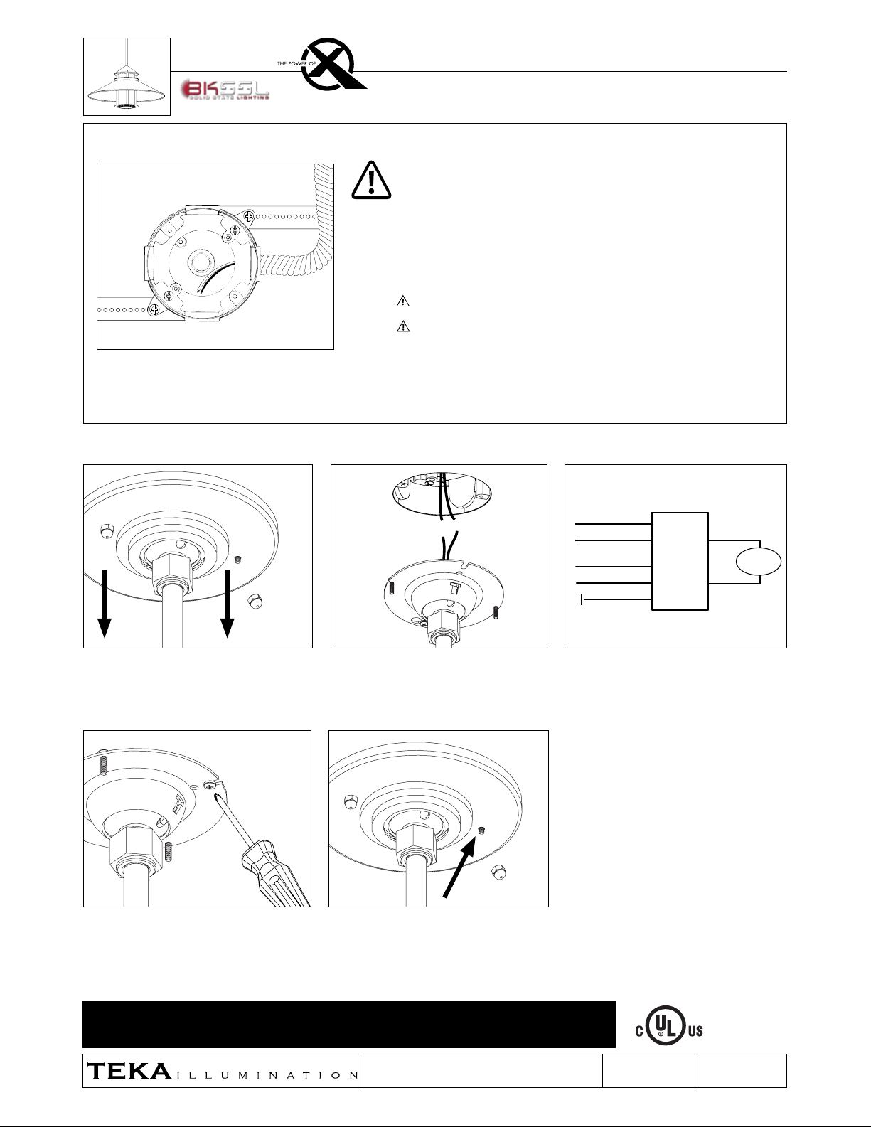
Installation of Fixture
Phase 1 - Rough In
Installation of Back box
1. Install Conduit (By Others) to be used with
this product.
2. Install junction box so that front face is flush
with finished ceiling.
3. Connect box to conduit and pull wires for
connections (See wiring diagram).
Additional Info
• Please follow National and Local electrical codes for your area.
• Suitable for through wire.
• Suitable for installation into combustible materials.
• Rated for 90° C.
• Junction box, universal mounting ring screws, box mounting hardware
and gaskets (By Others)
Use heavy-duty pendant adapter if luminaire weight exceeds 50 lbs.
Junction box must be secured to a structural member suitable for
weight of the luminaire and other weight likely to be placed upon it.
WIRING DIAGRAM
3. Secure canopy plate to junction box with
two (2) #6-32 Phillips screws using Phillips
screwdriver. Seal building envelope as per
NEC. Do not overtighten.
4. Slide decorative canopy cover up stem into
place and secure to mounting plate by hand-
tightening provided two (2) decorative cover
nuts.
1. Hand loosen then remove two (2) decorative
cover nuts, then slide decorative canopy down
stem to expose mounting plate.
2. Make watertight connections from remote
driver to fixture leads using waterproof wire
connectors (By Others). See wiring diagram.
LARGE BEACON STEM MOUNT™ (LBS)
LINE
Red
FIXTURE
COM
Hydrolock
Plate
Black
GROUND
Driver
White
Black
Green
DIM +
DIM -
Black
White
Hydrolock
Plate
Green
Driver
White
Black
White
Blue
Green
LINE
COM
GROUND
Orange
Orange
Brown
Blue
Black
Gray
FIXTURE
FIXTURE
Green
Green
LINE
Red
FIXTURE
COM
Driver
Black
GROUND
DIM +
DIM -
GROUND IN HOUSING
LINE
Red
FIXTURE
COM
Driver
Black
DIM +
DIM -
GROUND ON PLATE
LINE
Red
FIXTURE
COM
Driver
Black
DIM +
DIM -
HP2RM
HP2 TR
TMB
PCIII
Generic TR
GROUND IN HOUSING
LINE
Quick
Connect
COM
Driver FIXTURE
DIM +
DIM -
PM3
GROUND IN HOUSING
LINE
Quick
Connect
COM
Driver FIXTURE
DIM +
DIM -
Quick
Connect
Driver FIXTURE
DIM +
DIM -
PM3D
GROUND IN HOUSING
LINE
COM
Remote
Driver
DIM +
DIM -
Fixture
Fixture
PM3RM
GROUND ON PLATE
LINE
COM
Driver
DIM +
DIM -
PCIII
Quick
Connect
FIXTURE
LINE
Red
FIXTURE
COM
Remote
Driver
Black
DIM +
DIM -
MA/AP
GROUND
GROUND IN HOUSING
LINE
COM
Remote
Driver
DIM +
DIM -
DIM +
DIM -
PM3DRM
Fixture
Fixture
Remote
Driver
Fixture
Fixture

IMPORTANT SAFETY INFORMATION LISTED ON REVERSE
READ, FOLLOW, AND SAVE ALL SAFETY AND INSTALLATION INSTRUCTIONS
RELEASE DATE
5-4-18
40429 Brickyard Drive • Madera, CA 93636 • USA
559.438.5800 • FAX 559.438.5900
REFERENCE NUMBER
INS-2690-00
LARGE BEACON STEM MOUNT™ (LBS)
To Replace Components
Fragile! Do not pull on connector or wiring.
Handle with care.
4. Carefully remove LED module from heatsink.
Do not pull on connector or wiring. Handle
with care.
5. Use small pick tool to push connector off LED board
through two small slots behind connector. Once
loose, lift connector upwards and off board.
2. Loosen four (4) #4-40 set screws on dome lens optic
holder using 0.050” Allen wrench. Gently remove
dome lens.
8. Tighten four (4) #4-40 set screws on dome lens
optic holder using 0.050” Allen wrench.
1. Loosen (3) #10-24 set screws on cap with
5/32” Allen wrench. Retain screws in cap.
Twist fixture body, then pull away.
3. Loosen two (2) #4-40 screws with 0.050” Allen
wrench. Gently pull optic holder off heatsink.
Connector will only fit in one direction.
7. Press connector straight downwards into slot
on module to snap into place.
9. Line up body assembly ring to cap. Twist into
cap to secure. Line up holes in body assembly
with holes in cap. Secure by tightening three (3)
#10-24 set screws with 5/32” Allen wrench.
Warning: Do not over tighten set screw.
Doing so will compromise O-Ring seal and
will void warranty.
6. Spread thin, even layer of thermal paste on back
of new LED module. Place new LED module on
heatsink, lining up module with holes for screws.
Tighten two (2) #4-40 screws using 0.050” Allen
wrench to secure LED module to heatsink.
Other TEKA ILLUMINATION Lighting Equipment manuals


