Lepro 3200LM User manual

1
DS-90-934A
Please read these instructions thoroughly prior to installation, then store in a safe place for future reference.
LED MOTION-ACTIVATED
SECURITY LIGHT

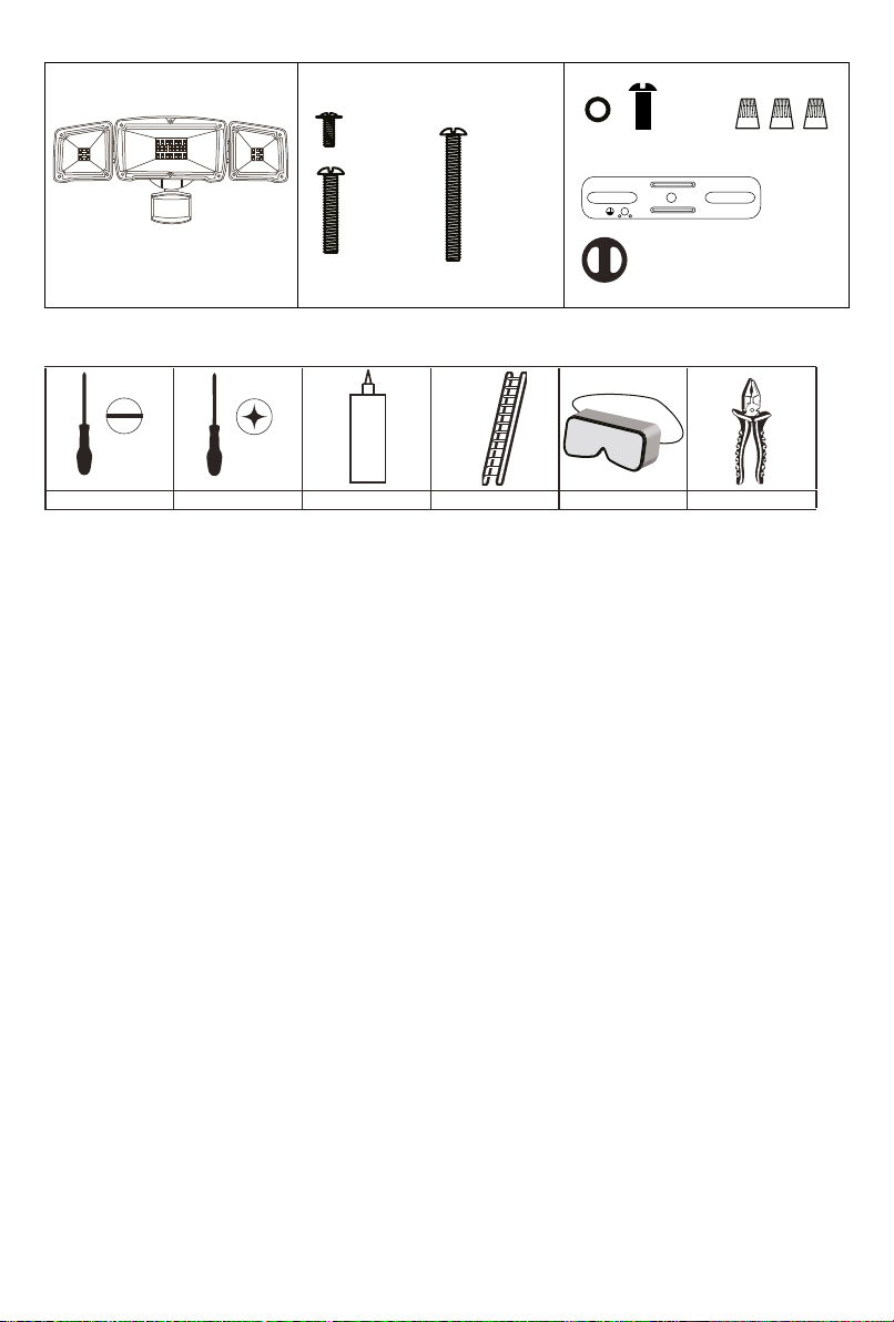
TOOLS REQUIRED (not included)
Flathead Screwdriver Screwdriver Silicone Sealant Step Ladder Eye Protection Pliers
2
PACKING LIST
NOTES:
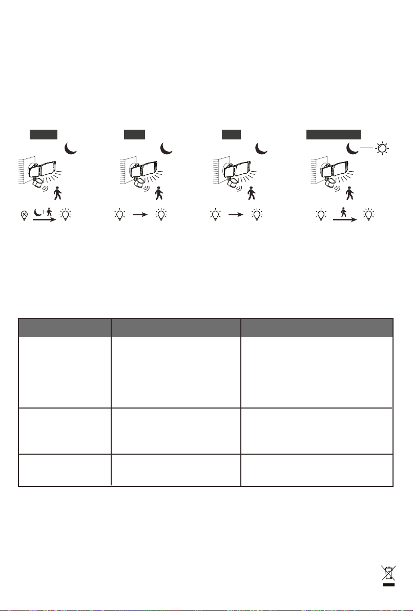
1. THE SECURITY LIGHT DETECTS A DISTANCE UP TO 49 FT., AT AN AMBIENT TEMPERATURE OF 77
DEGREES FAHRENHEIT, RH 30%-80%. TEMPERATURE CHANGES AFFECT THE DETECTION DISTANCE.
2. TO REDUCE POSSIBLE NUISANCES, DO NOT MOUNT THE FIXTURE NEAR A HEAT SOURCE LIKE AN AIR
CONDITIONER, VENT OR FURNACE EXHAUST, OR IN A DIRECTION FACING ANY REFLECTIVE OBJECT OR
OTHER NEARBY LIGHT SOURCE.
3. DO NOT PLACE THE SENSOR WITHIN A 1.5M RADIUS OF A REFLECTIVE OBJECT. A NEARBY REFLECTIVE
OBJECT WILL CAUSE THE LIGHTS TO FLASH.
SAFETY INFORMATION
Please read and understand this entire manual before attempting to assemble, operate or install the product.
PRODUCT MUST BE INSTALLED BY A QUALIFIED ELECTRICIAN!
WARNING
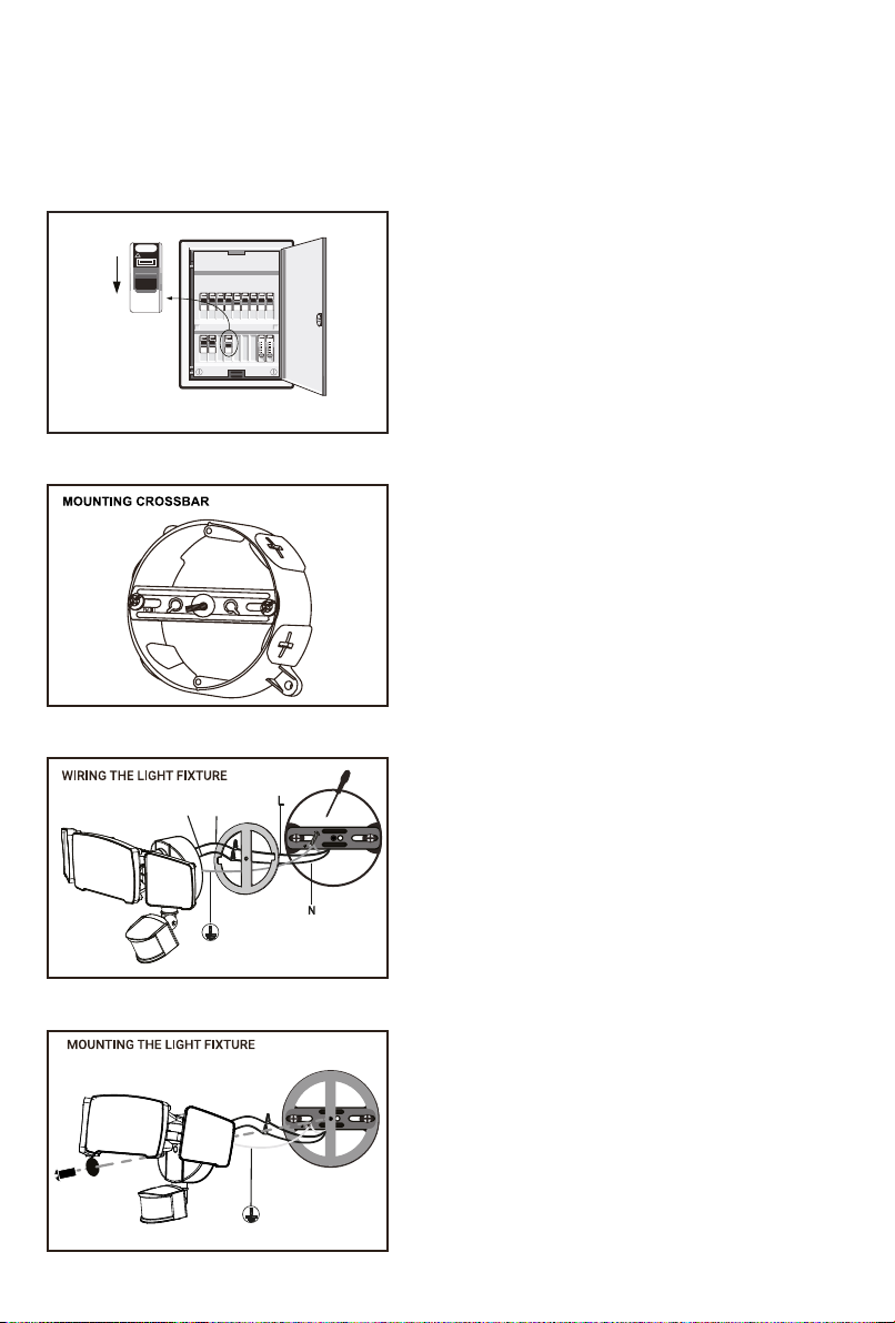
▲Shut off power at the circuit breaker or fuse panel before removing the old fixture or installing the new one.
▲LED electronics can be damaged by electrostatic discharge (ESD). Before installation, discharge the unit yourself by
touching a grounded bare metal surface to remove this hazard. To avoid damage, do not remove the clear lens over
the LED module.
CAUTION
DO NOT USE THIS FIXTURE WITH A DIMMING CIRCUIT.
If you currently have dimmer controls, you will need to remove them and replace them with regular electrical switches.
If you have a three-way dimmer, you will have to replace it with a regular three-way switch. If you are unfamiliar with
electrical installations, it is recommended you have a qualified electrician perform the installation.
IMPORTANT SAFETY INSTRUCTIONS
1. Turn the power OFF before installing or servicing.
2. Do NOT touch or install the fixture while in contact with standing water.
3. Do NOT remove the protective LED lens.
4. Do NOT look directly at lit LEDs for any length of time.
5. Do NOT leave bare wires exposed outside of the wall canopy enclosure.
6. Electrical requirements: 120V, 60Hz
7. Suitable for wall or eave mounting onto recessed or round surface mounted electrical boxes rated for wet location.
Not suitable for ground mount electrical boxes.
8. Do NOT allow the sensor head to touch the LED head housing. Maintain at least 1 in. spacing between the LED
heads and the sensor head.
9. For proper operation and protection against water damage, the motion sensor adjustment controls MUST be facing
downward.
10. Do NOT mount the unit lower than 5 ft.
SECURITY LIGHT
A: Screw x 1
(Painted Green)
B: Screw x 2
(M4*25MM)
B1: Screw x 1
(M4*60MM)
C: Ring + Nut D: Wire Nuts
E: Crossbar
F: EVA Gasket

PREPARATION
Before beginning the installation of this product, make sure all parts are present. Compare the received parts with the
packing list. If any part is missing or damaged, do not attempt to install the product.
Estimated Assembly Time: 30-60 minutes
PRODUCT MUST BE INSTALLED BY A QUALIFIED ELECTRICIAN!
3
ON
OFF
ON
OFF
OFF
1. Turn the power OFF to work area at main circuit breaker or
fuse box.
CAUTION: Do not rely on wall switch to turn the power off.
2. Attach crossbar (E) to junction box (not included) with two long
machine screws (B). Install the screw (B1) on the center hole,
make sure the screw thread is pointing away from the surface.
3. Remove the protective paper barrier from the adhesive face of
the EVA gasket (F) and adhere the gasket to the crossbar and
outer edge of the round surface junction box.
Ensure that the short machine screw on the crossbar is
threaded through the hole of EVA gasket.
Wire the light and junction box through the EVA gasket:
1). Connect the white wire from the light to the white wire on
the junction box by twisting Wire Nut (D).
2). Connect the black wire from the light to the black wire from
the junction box by twisting Wire Nut (D).
3). Connect the green/yellow wire from light to the ground wire
from junction box by using ground screw (A, painted green)
onto the crossbar.
4. Make sure all wire connections are secure.
Carefully place wires into junction box.
Position wall plate over the crossbar (E).
Mount the light onto the crossbar and secure with the NUTS
(C)
DO NOT over tighten.
For wet locations, make sure to fill any gaps of the EVA gasket
and mounting surface with a sealing compound or silicon glue.
Once all connections are complete and the silicone is dry, turn
on the power to the lights from the main junction box or circuit
breaker panel.
BlackWhite

RECOMMENDED INSTALL HEIGHT: 6.5-13 feet above the ground.
At this recommended height, the fixture will provide a detection distance of up to 49 feet, at 77 degrees Fahrenheit.
The sensor will be more sensitive to motion across rather than motion towards it directly.
4
Motion Sensor Horizontal
5ft.
Detection Coverage
Height
Sensor
Least Sensitive Most Sensitive
MotionMotion
IMPORTANT:
After mounting the motion-activated light, apply silicone sealant
completely around the perimeter of the cover plate where the back
of the cover plate meets the mounting surface. Silicone sealant
prevents water from seeping into the junction box.
CAUTION:
Make sure the motion detector head is not UPSIDE DOWN! Rotate
the motion sensor so that the controls face the detection areas.
ADJUSTING THE SENSOR HEAD:
Aim the sensor head toward the desired detection area and make
sure it is positioned with controls facing the ground.
You can adjust the sensor head up and down, left to right for the
desired coverage area.
7ft.
Motion Sensor Downward 5°
Detection Coverage
Height
9ft. Motion Sensor Downward 10°
Detection Coverage
Height
Installation is now complete. Turn on power at circuit breaker and flip wall switch to ON position. The wall switch
must remain in the ON position for the motion detector to work properly at all times (including daytime).
SENSOR ANGLES 180°
TEST
AUTO 3H 6H
TIME
L H
SENS
M
1MIN5MIN 10MIN
DUSK TO DAWN

5
1) TIME SETTING: Time Delay
TEST: Help to quickly adjust and test the fixture. FOR TESTING ONLY.
When the motion sensor detects you, the light will turn on for 6 seconds at any time (day/night).
1 MIN: the light(s) will remain on for 1 min after motion detection at night.
5 MIN: the light(s) will remain on for 5 min after motion detection at night.
10 MIN: the light(s) will remain on for 10 min after motion detection at night.
2) SENSITIVITY SETTING: Maximum detection distance
H: High sensitivity, up to 49 FT (max detection distance for this light)
M: Medium sensitivity, up to 36 FT
L: Low sensitivity, up to 26 FT
NOTE: At an ambient temperature of 77 degrees Fahrenheit, the detection distance is at its max. As the temperature increases or
decreases, the detection distance is affected.
OPERATING INSTRUCTIONS:
There are many changeable settings. Please set the settings that meet your needs.
TEST
AUTO 3H 6H
TIME
L H
SENS
M
1MIN5MIN 10MIN
DUSK TO DAWN
H
3.3
9.8
15.1
21.2
26.2
30.4
36.1
42.7
49.2
55.8
62.3
68.9
M
3.3
9.8
15.1
21.2
26.2
30.4
36.1
42.7
49.2
55.8
62.3
68.9
L
3.3
9.8
15.1
21.2
26.2
30.4
36.1
42.7
49.2
55.8
62.3
68.9
Motion Sensor Sensitivity Diagram
When 2 infrared rays (dots in the diagram) are triggered, the sensor will be triggered.

TROUBLES SHOOTING
3) MODE
AUTO:
The light acts as an automatic sensor at night. When motion is detected, the light will activate at its maximum brightness.
If you select this option, you can set the lighting time and the sensitivity of the sensor simultaneously.
3H:
At dusk, the light will be low for 3 hours, and when motion is detected, it will turn to high. After 3 hours it will switch to
Auto mode.
6H:
At dusk, the light will be low for 6 hours, and when motion is detected, it will turn to high. After 6 hours, it will switch to
Auto mode.
Dusk to Dawn:
From night to dawn, the light will stay on low. When motion is detected, it will switch to highlight mode.
MAINTENANCE:
Any cleaning or maintenance of the lights should be done with the power turned off. The lamp should be wiped clean with a damp cloth.
Do not use any abrasive cleaning products on the lamp cap or motion sensor lens. Don't add paint to the lamp. Do not use
high-pressure nozzles for cleaning. Regularly check whether the silica gel or sealant is still in place and that the lamp is still firmly
affixed on the wall.
PROBLEM
CAUSE
CORRECTIVE ACTION
Light does not come on
at night when motion is
detected
No power is being delivered to the
light.
Another light source is causing the
security light to think it is daylight.
The wiring inside the electrical box
came loose.
Check that the circuit breaker and /or wall
switch power is on.
Turn off surrounding lights and/or re-aim
the sensor head.
After turning power off to the light,
reconnect any loose wiring.
The sensor is in a shaded area and
is fooled into thinking it is nighttime.
Shine a flashlight onto the light sensor.
Relocate the security light to a location
that allows enough light enter the sensor
during the daytime.
There is lighting, arc welding, mobile
sources or other such unstable light
nearby.
Relocate the light to another location to
avoid such light sources.
Security light comes on
during the day
The light flashes on
and off
1.
2.
3.
1.
2.
3.
1.
2.
The device complies with part 15 of the FCC Rules. Operation is subject to the following two conditions (1) This device may not cause harmful
interference, and (2) this device must accept any interference received, including interference that may cause undesired operation.
LE Innovation Inc
3651 Lindell Rd Ste D, Las Vegas, NV 89103, USA
Made in China Fabriqué en Chine
AUTO
Auto
3H
Low for 3 hOff On
6H Dusk to Dawn
Low for all night High
AutoLow for 6 h
This manual suits for next models
1
Table of contents
Other Lepro Lighting Equipment manuals
Popular Lighting Equipment manuals by other brands

IMG STAGE LINE
IMG STAGE LINE LSX-142SRGY StageLine user manual

Show Tec
Show Tec LED Par 56 Short Eco V2 manual

Aspect LED
Aspect LED Touch! installation guide

Lightmybricks
Lightmybricks LEGO HOGWARTS ICONS installation guide

HQ Power
HQ Power VDP250MH6/2 user manual

PRISM+
PRISM+ CLAYMORE ULTRA+ II Series user manual