manuals.online logo
Brands
  1. Home
  2. •
  3. Brands
  4. •
  5. TEKA ILLUMINATION
  6. •
  7. Outdoor Light
  8. •
  9. TEKA ILLUMINATION TR5 User manual

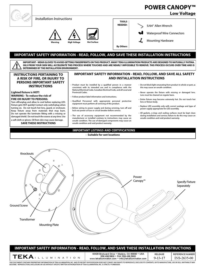
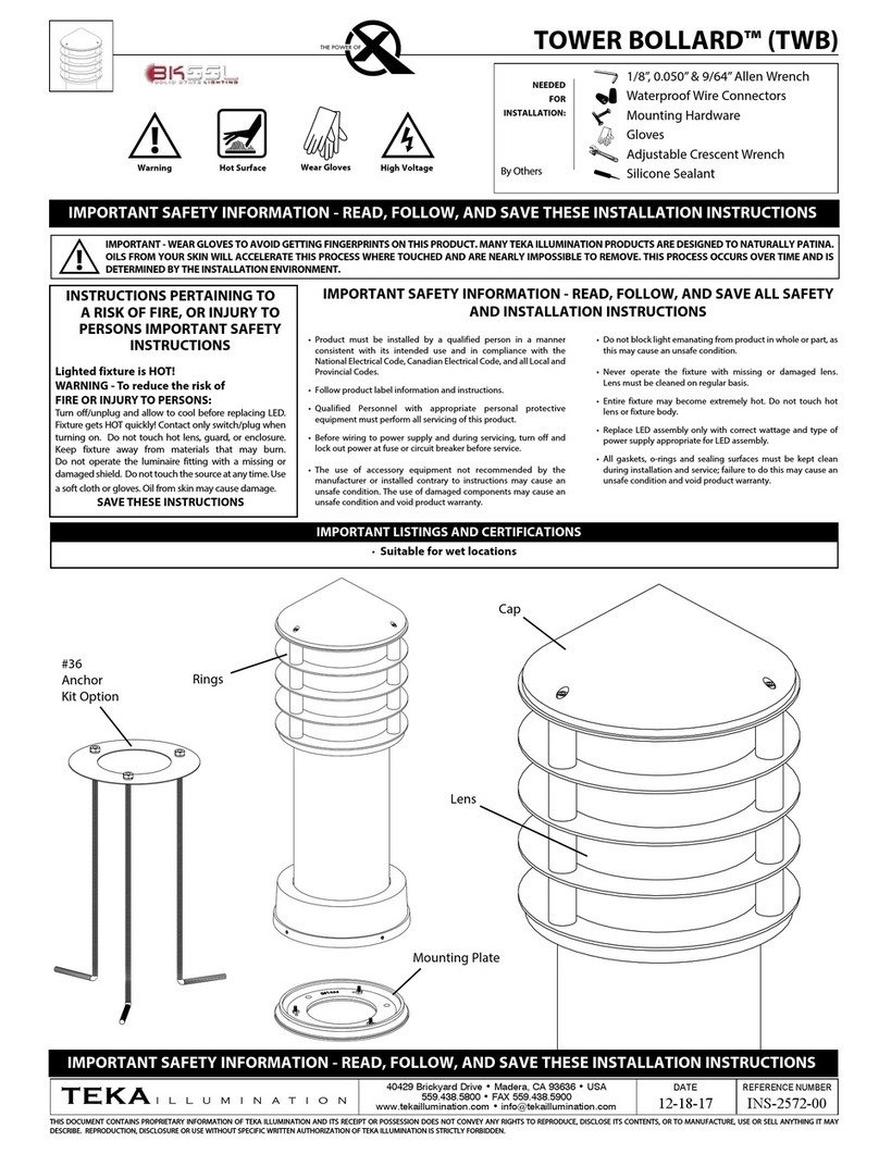
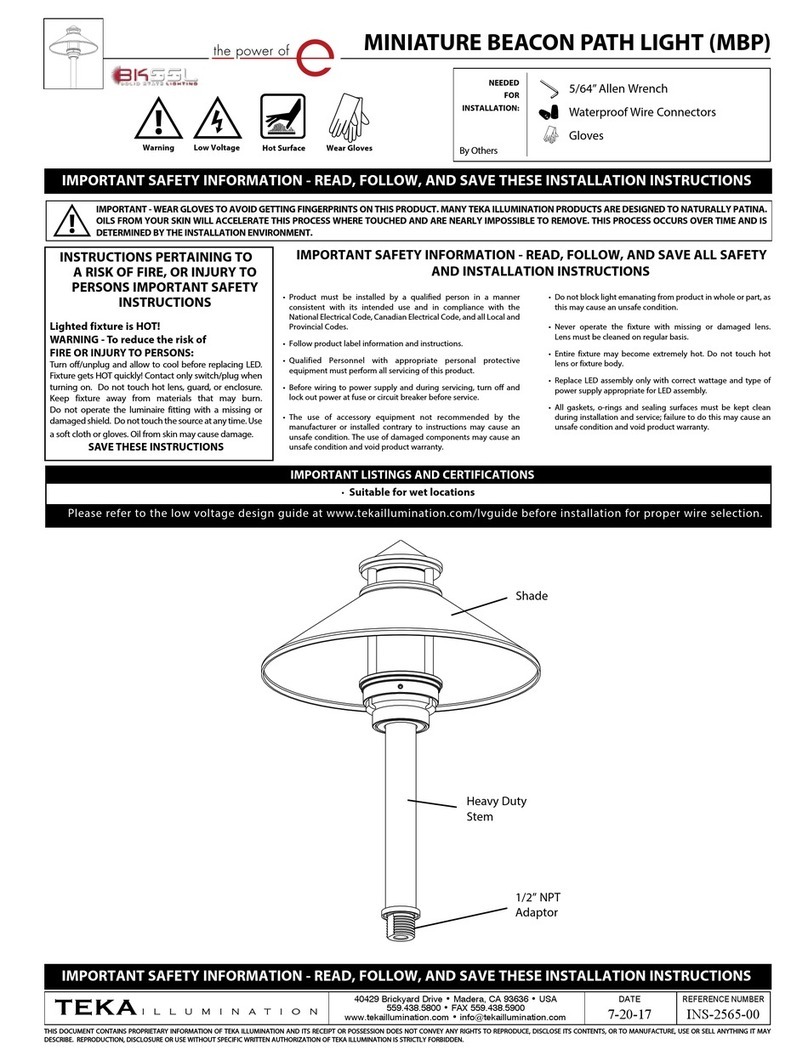
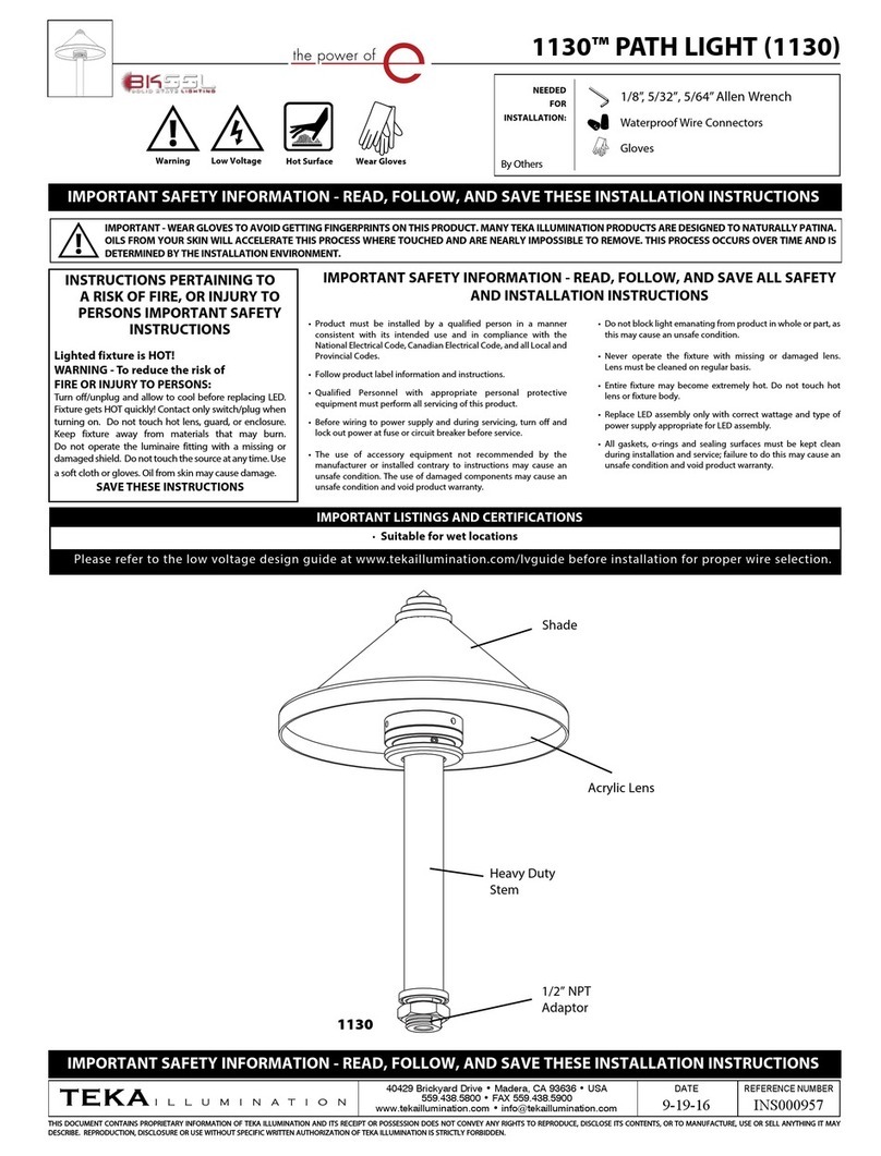
TEKA ILLUMINATION TR5 User manual

THIS DOCUMENT CONTAINS PROPRIETARY INFORMATION OF TEKA ILLUMINATION AND ITS RECEIPT OR POSSESSION DOES NOT CONVEY ANY RIGHTS TO REPRODUCE, DISCLOSE ITS CONTENTS, OR TO MANUFACTURE, USE
OR SELL ANYTHING IT MAY DESCRIBE. REPRODUCTION, DISCLOSURE OR USE WITHOUT SPECIFIC WRITTEN AUTHORIZATION OF TEKA ILLUMINATION IS STRICTLY FORBIDDEN.
5/32”, 5/64” & 0.050” Allen Wrench
Warning Hot Surface
NEEDED
FOR
INSTALLATION:
RELEASE DATE
08/03/2021
REFERENCE NUMBER
INS-2847-00
40429 Brickyard Drive • Madera, CA 93636 • USA
559.438.5800 • FAX 559.438.5900
www.tekaillumination.com • [email protected]
Bracket
TR5
High Voltage
Shade
Ring Stack
Cylinder Lens
LWB POLE MOUNT - TR5 (LBW-TR5)
· Suitable for wet locations
IMPORTANT LISTINGS AND CERTIFICATIONS
IMPORTANT SAFETY INFORMATION - READ, FOLLOW, AND SAVE THESE INSTALLATION
INSTRUCTIONS
• Product must be installed by a qualified person in a manner
consistent with its intended use and in compliance with the
National Electrical Code, Canadian Electrical Code, and all Local
and Provincial Codes.
• Follow product label information and instructions.
• Qualified Personnel with appropriate personal protective
equipment must perform all servicing of this product.
• Before wiring to power supply and during servicing, turn off and
lock out power at fuse or circuit breaker before service.
• The use of accessory equipment not recommended by the
manufacturer or installed contrary to instructions may cause an
unsafe condition. The use of damaged components may cause
an unsafe condition and void product warranty.
IMPORTANT SAFETY INFORMATION - READ, FOLLOW, AND SAVE ALL
SAFETY AND INSTALLATION INSTRUCTIONS
• Do not block light emanating from product in whole or part,
as this may cause an unsafe condition.
• Never operate the fixture with missing or damaged lens.
Lens must be cleaned on regular basis.
• Entire fixture may become extremely hot. Do not touch hot
lens or fixture body.
• Replace LED assembly only with correct wattage and type
of power supply appropriate for LED assembly.
• All gaskets, o-rings and sealing surfaces must be kept clean
during installation and service; failure to do this may cause
an unsafe condition and void product warranty.
INSTRUCTIONS PERTAINING TO
A RISK OF FIRE, OR INJURY
TO PERSONS IMPORTANT
SAFETY INSTRUCTIONS
Lighted fixture is HOT!
WARNING - To reduce the risk of
FIRE OR INJURY TO PERSONS:
Turn off/unplug and allow to cool before replacing LED.
Fixture gets HOT quickly! Contact only switch/plug when
turning on. Do not touch hot lens, guard, or enclosure.
Keep fixture away from materials that may burn.
Do not operate the luminaire fitting with a missing or
damaged shield. Do not touch the source at any time.
Use a soft cloth or gloves. Oil from skin may cause
damage.
SAVE THESE INSTRUCTIONS
Cap
IMPORTANT SAFETY INFORMATION - READ, FOLLOW, AND SAVE THESE INSTALLATION
INSTRUCTIONS
Phase 1 - Install Pole
Installation of pole.
1. Install pole according to lighting plan. Install
conduit (by others) to be used with this
product.
2. Pull wiring necessary for installation (by
others.)
Leave sufficient wire length in the pole for
future service.
Install as per NEC for location.
5. Secure pole base to anchor bolts using
provided hardware with anchor bolt kit.
Tighten securely to prevent hardware from
loosening.
3. Install anchor bolts according to detail to allow
pole leveling. Use caution when setting anchor
bolts. Bolts must be vertically straight.
Pole Hinges this Direction
4. To assure proper operation of the hinge
mechanism, the electrical supply conduit
must not project more than 1-1/2” above the
surface of the concrete.
8 1/2” DIA. MINIMUM
BOLT CIRCLE
12 11/16”
7 1/16”
6”
10” DIA. MINIMUM
BOLT CIRCLE
1. Mounting base is 12-11/16” round with a bolt
circle of 8-1/2” to 10” in diameter.
(4) 17" x 3” x 3/4" J- Shaped
Anchors Bolts
3/4" Hardware
Grade
Conduit Reference
1-1/2" ID Conduit
(By Others)
2. Dig hole for conduit installation and deep
enough for anchor bolts and concrete footing.
See anchor bolt detail step.
Adequate drainage must be provided in
concrete foundation or grout.
6. To tilt pole over hinge base, loosen the three (3)
1/2”-13 stainless bolts. Carefully lower pole into
a resting position.
7. If pole comes with cover, place cover on
the base of the pole. Secure with the four
(4) 1/4”-20 hex screws using a 3/16” allen
wrench.
RELEASE DATE
08/03/2021
40429 Brickyard Drive • Madera, CA 93636 • USA
559.438.5800 • FAX 559.438.5900
www.tekaillumination.com • [email protected]
REFERENCE NUMBER
INS-2847-00
LWB POLE MOUNT - TR5 (LBW-TR5)
Installation Instructions
IMPORTANT SAFETY INFORMATION LISTED ON REVERSE
READ, FOLLOW, AND SAVE ALL SAFETY AND INSTALLATION
INSTRUCTIONS
RELEASE DATE
08/03/2021
40429 Brickyard Drive • Madera, CA 93636 • USA
559.438.5800 • FAX 559.438.5900
www.tekaillumination.com • [email protected]
REFERENCE NUMBER
INS-2847-00
WIRING DIAGRAM1. Attach threaded stem to pole. Attach support
bracket to the stem. Bolt down support bracket
to stem using the hardware provided and a bolt
down bracket to pole using hardware provided
with a 3/16 allen wrench.
2. Connect remote driver secondary wiring to
fixture leads using watertight wire connectors
(by others) as per NEC. Place wiring and
connections into junction box. See wiring
diagram.
LWB POLE MOUNT - TR5 (LBW-TR5)
LINE
Red
FIXTURE
COM
Hydrolock
Plate
Black
GROUND
Driver
White
Black
Green
DIM +
DIM -
Black
White
Hydrolock
Plate
Green
Driver
White
Black
White
Blue
Green
LINE
COM
GROUND
Orange
Orange
Brown
Blue
Black
Gray
FIXTURE
FIXTURE
Green
Green
LINE
Red
FIXTURE
COM
Driver
Black
GROUND
DIM +
DIM -
GROUND IN HOUSING
LINE
Red
FIXTURE
COM
Driver
Black
DIM +
DIM -
GROUND ON PLATE
LINE
Red
FIXTURE
COM
Driver
Black
DIM +
DIM -
HP2RM
HP2 TR
TMB
PCIII
Generic TR
GROUND IN HOUSING
LINE
Quick
Connect
COM
Driver FIXTURE
DIM +
DIM -
PM3
GROUND IN HOUSING
LINE
Quick
Connect
COM
Driver FIXTURE
DIM +
DIM -
Quick
Connect
Driver FIXTURE
DIM +
DIM -
PM3D
GROUND IN HOUSING
LINE
COM
Remote
Driver
DIM +
DIM -
Fixture
Fixture
PM3RM
GROUND ON PLATE
LINE
COM
Driver
DIM +
DIM -
PCIII
Quick
Connect
FIXTURE
LINE
Red
FIXTURE
COM
Remote
Driver
Black
DIM +
DIM -
MA/AP
GROUND
GROUND IN HOUSING
LINE
COM
Remote
Driver
DIM +
DIM -
DIM +
DIM -
PM3DRM
Fixture
Fixture
Remote
Driver
Fixture
Fixture
3. Connect secondary leads in stem with
secondary leads from fixture body with quick
disconnect.
4. Slide fixture body onto stem, then secure by
tightening two (2) #8-32 set screws with a
5/64” allen wrench.
Phase 1 - Fixture Installation
Installation Instructions
IMPORTANT SAFETY INFORMATION LISTED ON REVERSE
READ, FOLLOW, AND SAVE ALL SAFETY AND INSTALLATION
INSTRUCTIONS
RELEASE DATE
08/03/2021
40429 Brickyard Drive • Madera, CA 93636 • USA
559.438.5800 • FAX 559.438.5900
www.tekaillumination.com • [email protected]
REFERENCE NUMBER
INS-2847-00
9. Line up body assembly ring to cap. Twist into
cap to secure. Line up holes in body assembly
with holes in cap. Secure by tightening three
(3) #10-24 set screws with a 5/32” allen
wrench.
Warning: Do not over tighten set screw.
Doing so will compromise o-ring seal and
will void warranty.
To Replace Components
1. Loosen (3) #10-24 set screws on cap with a
5/32” allen wrench. Retain screws in cap.
Twist fixture body, then pull away.
3. Loosen two (2) #4-40 screws with a 0.050”
allen wrench. Gently pull optic holder off
heatsink.
Fragile! Do not pull on connector or wiring.
Handle with care.
4. Carefully remove LED module from heatsink.
Do not pull on connector or wiring. Handle
with care.
5. Use small pick tool to push connector off LED
board through two small slots behind connector.
Once loose, lift connector upwards and off board.
Connector will only fit in one direction.
2. Loosen four (4) #4-40 set screws on dome lens
optic holder using a0.050” allen wrench. Gently
remove dome lens optic and optic holder.
6. Spread thin, even layer of thermal paste on
back of new LED module. Place new LED
module on heatsink, lining up module with
holes for screws.
Tighten two (2) #4-40 screws using a 0.050”
allen wrench to secure LED module to
heatsink.
8. Place dome lens and optic holder back onto cap.
Tighten four (4) #4-40 set screws on dome lens
optic holder using a0.050” allen wrench.
7. Press connector straight downwards into
slot on module to snap into place.
LWB POLE MOUNT - TR5 (LBW-TR5)
Installation Instructions
IMPORTANT SAFETY INFORMATION LISTED ON REVERSE
READ, FOLLOW, AND SAVE ALL SAFETY AND INSTALLATION
INSTRUCTIONS

Other TEKA ILLUMINATION Outdoor Light manuals

TEKA ILLUMINATION POWER CANOPY User manual

TEKA ILLUMINATION

TEKA ILLUMINATION POWER CANOPY User manual

TEKA ILLUMINATION BEACON WALL MOUNT User manual

TEKA ILLUMINATION

TEKA ILLUMINATION BEACON WALL MOUNT User manual

TEKA ILLUMINATION TOWER BOLLARD User manual

TEKA ILLUMINATION

TEKA ILLUMINATION TOWER BOLLARD User manual

TEKA ILLUMINATION 1130 User manual

TEKA ILLUMINATION

TEKA ILLUMINATION 1130 User manual

TEKA ILLUMINATION MBP User manual

TEKA ILLUMINATION

TEKA ILLUMINATION MBP User manual

TEKA ILLUMINATION PRP User manual

TEKA ILLUMINATION

TEKA ILLUMINATION PRP User manual

TEKA ILLUMINATION LARGE BEACON WALL MOUNT User manual

TEKA ILLUMINATION

TEKA ILLUMINATION LARGE BEACON WALL MOUNT User manual

TEKA ILLUMINATION TMC User manual

TEKA ILLUMINATION

TEKA ILLUMINATION TMC User manual

Popular Outdoor Light manuals by other brands

Trio 281570906 quick guide

Trio

Trio 281570906 quick guide

LIGMAN LADOR 3 installation manual

LIGMAN

LIGMAN LADOR 3 installation manual

LIGMAN ABERDEEN 2 installation manual

LIGMAN

LIGMAN ABERDEEN 2 installation manual

NERI Nebula S Installation guides

NERI

NERI Nebula S Installation guides

ZANEEN Moon Installation instruction

ZANEEN

ZANEEN Moon Installation instruction

Astonica 50402521 instruction manual

Astonica

Astonica 50402521 instruction manual

BEGA 84 137 Instructions for use

BEGA

BEGA 84 137 Instructions for use

Landscape Forms Lo-Glo installation guide

Landscape Forms

Landscape Forms Lo-Glo installation guide

Sunnydaze Decor DW Series user manual

Sunnydaze Decor

Sunnydaze Decor DW Series user manual

LIGMAN QA-50022 instruction manual

LIGMAN

LIGMAN QA-50022 instruction manual

Saxby Lighting Bosco 1612T35A Instruction leaflet

Saxby Lighting

Saxby Lighting Bosco 1612T35A Instruction leaflet

Marecoluce Indus Series Use and maintenance instructions

Marecoluce

Marecoluce Indus Series Use and maintenance instructions

Kartell Bourgie manual

Kartell

Kartell Bourgie manual

Fumagalli GERMANA quick start guide

Fumagalli

Fumagalli GERMANA quick start guide

Bailey 145110 manual

Bailey

Bailey 145110 manual

FLOS BON JOUR VERSAILLES F1041015 Instruction for correct Installation and Use

FLOS

FLOS BON JOUR VERSAILLES F1041015 Instruction for correct Installation and Use

LEDDOO ROME user manual

LEDDOO

LEDDOO ROME user manual

Astrapool 52717 quick start guide

Astrapool

Astrapool 52717 quick start guide

manuals.online logo
manuals.online logoBrands
  • About & Mission
  • Contact us
  • Privacy Policy
  • Terms and Conditions

Copyright 2025 Manuals.Online. All Rights Reserved.