Tekelec EAGLE 5 User manual

Tekelec EAGLE® 5
Integrated Signaling System
SIGTRAN User Guide
910-5346-001 Revision A
September 2008

Copyright 2008 Tekelec
All Rights Reserved.
Printed in U.S.A.
Notice
Information in this documentation is subject to change without notice. Unauthorized use, copying, or translation of this
documentation can result in civil or criminal penalties.
Any export of Tekelec products is subject to the export controls of the United States and the other countries where Tekelec has
operations.
No part of this documentation may be reproduced, translated, or transmitted in any form or by any means, electronic or
mechanical, including photocopying or recording, for any purpose without the express written permission of an authorized
representative of Tekelec.
Other product names used herein are for identification purposes only, and may be trademarks of their respective companies.
RoHS 5/6 - As of July 1, 2006, all products that comprise new installations shipped to European Union member countries will
comply with the EU Directive 2002/95/EC "RoHS" (Restriction of Hazardous Substances). The exemption for lead-based
solder described in the Annex will be exercised. RoHS 5/6 compliant components will have unique part numbers as reflected
in the associated hardware and installation manuals.
WEEE - All products shipped to European Union member countries comply with the EU Directive 2002/96/EC, Waste
Electronic and Electrical Equipment. All components that are WEEE compliant will be appropriately marked. For more
information regarding Tekelec's WEEE program, contact your sales representative.
Trademarks
The Tekelec logo, EAGLE, G-Flex, G-Port, IP7, IP7 Edge, and IP7 Secure Gateway are registered trademarks of Tekelec.
TekServer, A-Port, and V-FLEX are trademarks of Tekelec. All other trademarks are the property of their respective owners.
Patents
This product is covered by one or more of the following U.S. and foreign patents:
U.S. Patent Numbers:
5,732,213; 5,953,404; 6,115,746; 6,167,129; 6,324,183; 6,327,350; 6,456,845; 6,606,379; 6,639,981; 6,647,113; 6,662,017;
6,735,441; 6,745,041; 6,765,990; 6,795,546; 6,819,932; 6,836,477; 6,839,423; 6,885,872; 6,901,262; 6,914,973; 6,940,866;
6,944,184; 6,954,526;6,954,794; 6,959,076; 6,965,592; 6,967,956; 6,968,048; 6,970,542; 6,987,781; 6,987,849; 6,990,089;
6,990,347; 6,993,038; 7,002,988; 7,020,707; 7,031,340; 7,035,239; 7,035,387; 7,043,000; 7,043,001; 7,043,002; 7,046,667;
7,050,456; 7,050,562; 7,054,422; 7,068,773; 7,072,678; 7,075,331; 7,079,524; 7,088,728; 7,092,505; 7,108,468; 7,110,780;
7,113,581; 7,113,781; 7,117,411; 7,123,710; 7,127,057; 7,133,420; 7,136,477; 7,139,388; 7,145,875; 7,146,181; 7,155,206;
7,155,243; 7,155,505; 7,155,512; 7,181,194; 7,190,702; 7,190,772; 7,190,959; 7,197,036; 7,206,394; 7,215,748; 7,219,264;
7,222,192; 7,227,927; 7,231,024; 7,242,695; 7,254,391; 7,260,086; 7,260,207; 7,283,969; 7,286,516; 7,286,647; 7,286,839;
7,295,579; 7,299,050; 7,301,910; 7,304,957; 7,318,091; 7,319,857; 7,327,670
Foreign Patent Numbers:
EP1062792; EP1308054; EP1247378; EP1303994; EP1252788; EP1161819; EP1177660; EP1169829; EP1135905;
EP1364520; EP1192758; EP1240772; EP1173969; CA2352246
Ordering Information
Your Tekelec Sales Representative can provide you with information about how to order additional discs.

Table of Contents
Chapter 1. Introduction ..................................................................................................... 1-1
About this manual ....................................................................................................................... 1-1
Audience ..................................................................................................................................... 1-2
Updates for this Release ............................................................................................................. 1-2
Manual organization ................................................................................................................... 1-2
Manual conventions .................................................................................................................... 1-3
Documentation Admonishments ................................................................................................ 1-3
Customer Care Center ................................................................................................................ 1-4
Emergency Response .................................................................................................................. 1-4
Related Publications ................................................................................................................... 1-5
Documentation Availability, Packaging, and Updates ............................................................... 1-5
Locate Product Documentation on the Customer Support Site .................................................. 1-6
Chapter 2. SS7-over-IP networks ..................................................................................... 2-1
SS7-over-IP networks overview ................................................................................................. 2-1
SS7 limitations ............................................................................................................................ 2-2
Role of SIGTRAN ...................................................................................................................... 2-2
SCTP (Stream Control Transmission Protocol) .................................................................. 2-3
M2PA (MTP2 User Peer-to-Peer Adaptation Layer) protocol ........................................... 2-4
M3UA (MTP Level 3 User Adaptation Layer) protocol ..................................................... 2-5
SUA (SCCP User Adaptation) protocol .............................................................................. 2-6
SS7-over-IP signaling transport .................................................................................................. 2-6
From SS7 message to IP packet .......................................................................................... 2-7
Communication inside the Wide Area Network (WAN) .................................................... 2-7
Reasons to transition to an SS7-over-IP SIGTRAN network ..................................................... 2-8
Cost effectiveness ................................................................................................................ 2-8
Increased capacity ............................................................................................................... 2-9
Integration ........................................................................................................................... 2-9
Type of network change ........................................................................................................... 2-10
Dedicated network versus converged IP networkt ............................................................ 2-10
Replacement versus expansion .......................................................................................... 2-10
Diversity ............................................................................................................................ 2-11
When to transition to an SS7-over-IP SIGTRAN network ...................................................... 2-11
Chapter 3. Tekelec solutions ............................................................................................. 3-1
Overview .................................................................................................................................... 3-1
EAGLE 5 ISS ............................................................................................................................. 3-1
IPLIMx, IPGWx and IPSG applications ............................................................................. 3-2
Tekelec Integrated Application Solutions (IAS) ........................................................................ 3-3
910-5346-001 Revision A, September 2008 i

Integrated Message Feeder (IMF) .............................................................................................. 3-4
Chapter 4. Transition planning ........................................................................................ 4-1
Transition guidelines .................................................................................................................. 4-1
Resolve high-level network design ..................................................................................... 4-1
Collect network information ............................................................................................... 4-2
Analyze data ........................................................................................................................ 4-4
Prepare configurations ......................................................................................................... 4-4
Implement and test .............................................................................................................. 4-4
Refine timers and parameters .............................................................................................. 4-5
Chapter 5. Dimensioning ................................................................................................... 5-1
About bandwidth, throughput, transaction units, and TPS ......................................................... 5-1
Transactions versus transaction units and TPS ................................................................... 5-2
Scalability ................................................................................................................................... 5-2
Link equivalency ................................................................................................................. 5-2
Hardware and software requirements .................................................................................. 5-4
System capacity ................................................................................................................... 5-5
Achieving IP Signaling Applications’ Advertised Capacity ...................................................... 5-5
Factors affecting advertised capacity .................................................................................. 5-6
Base transaction unit ........................................................................................................... 5-6
Adjusted transaction unit ..................................................................................................... 5-8
How to calculate transaction units per second (TPS) .......................................................... 5-8
Functionality of configurable SCTP buffer sizes per association ..................................... 5-10
System constraints affecting total IP Signaling capacity .................................................. 5-11
SIGTRAN engineering guidelines ............................................................................................ 5-13
Calculate the number of cards required ............................................................................. 5-15
IPGWx congestion management options ................................................................................. 5-16
Redundancy and link engineering ............................................................................................ 5-16
Unihoming versus multihoming ........................................................................................ 5-17
Choosing a redundancy method for M2PA links .............................................................. 5-18
Mated Signal Transfer Point redundancy .......................................................................... 5-18
IPGWx mateset .................................................................................................................. 5-19
Signaling Link Selection (SLS) routing ............................................................................ 5-20
LAN/WAN considerations ....................................................................................................... 5-20
Retransmission concept ............................................................................................................ 5-21
Retransmissions and destination status ............................................................................. 5-21
SCTP timers ...................................................................................................................... 5-21
Configure Congestion Window Minimum (CWMIN) parameter ..................................... 5-23
Chapter 6. Implementation ............................................................................................... 6-1
Hardware requirements ............................................................................................................... 6-1
EAGLE 5 ISS ...................................................................................................................... 6-1
Integrated Message Feeder (IMF) ....................................................................................... 6-2
Converting non-IPSG-M2PA Linksets to IPSG-M3UA Linksets .............................................. 6-2
Converting IPGWx M3UA Application Servers to IPSG-M3UA Linksets ............................... 6-3
IPGWx to IPSG-M3UA Conversion Example 1 ................................................................. 6-3
IPGWx to IPSG-M3UA Conversion Example 2 ................................................................. 6-5
IPGWx to IPSG-M3UA Conversion Example 2A .............................................................. 6-7
Table of Contents SIGTRAN User Guide
ii 910-5346-001 Revision A, September 2008

Configuration .............................................................................................................................. 6-9
Configure the IPSG application .......................................................................................... 6-9
Configure the IPSG Application on the Same Card .......................................................... 6-10
Configure the IPLIMx application .................................................................................... 6-11
Configure the IPGWx application ..................................................................................... 6-12
Refine timers and parameters ................................................................................................... 6-15
Define RTIMES association retransmits ........................................................................... 6-15
Define RTO parameter ...................................................................................................... 6-15
Measure jitter ..................................................................................................................... 6-15
Refine RTO parameter ...................................................................................................... 6-15
System verification ................................................................................................................... 6-16
Verify network connectivity .............................................................................................. 6-16
Verify IPLIMx configuration ............................................................................................ 6-17
Verify IPGWx configuration ............................................................................................ 6-18
Chapter 7. Troubleshooting .............................................................................................. 7-1
General troubleshooting ............................................................................................................. 7-1
Verify UIMs and UAMs ............................................................................................................. 7-2
Is the card configured correctly? ................................................................................................ 7-2
Connection does not become established ................................................................................... 7-3
Connection bounces and is unstable ........................................................................................... 7-3
AS/PC in route key does not become available or ACTIVE (IPGWx only) .............................. 7-3
IP destination is not informed of SS7 destination status changes; network management is
not working correctly (IPGWx only) .................................................................................. 7-4
Traffic not arriving at IP destination or traffic is lost ................................................................. 7-4
Are connection(s) congesting? ................................................................................................... 7-4
Traffic not load-balanced properly ............................................................................................. 7-5
Link level events ......................................................................................................................... 7-5
Association ................................................................................................................................. 7-5
Appendix A. Additional Deployment Scenarios ............................................................. A-1
IPLIM/M2PA deployment scenarios ......................................................................................... A-1
Simple M2PA A-link configuration (3,000 TPS) ............................................................... A-1
High-throughput M2PA A-link configuration (30,000 TPS) ............................................. A-2
High-throughput M2PA C-link configuration (30,000 TPS) ............................................. A-3
IPLIM/M2PA deployment scenarios ......................................................................................... A-3
Simple M2PA A-link configuration (3,000 TPS) ............................................................... A-3
High-throughput M2PA A-link configuration (30,000 TPS) ............................................. A-4
High-throughput M2PA C-link configuration (30,000 TPS) ............................................. A-5
IPGW/M3UA deployment scenarios ......................................................................................... A-5
Active/standby configurations ............................................................................................ A-5
Two-pair IPGWx ................................................................................................................ A-6
Four IPGWx pairs (two SS7IPW pairs and two IPGWI pairs) .......................................... A-7
Eight IPGWx cards, two mates, three linksets ................................................................... A-8
Four IPGWx cards, one linkset for end office .................................................................... A-9
Unsupported Scenarios ....................................................................................................... A-9
Appendix B. References .................................................................................................... B-1
Tekelec internal references ........................................................................................................ B-1
SIGTRAN User Guide Table of Contents
910-5346-001 Revision A, September 2008 iii

External References ................................................................................................................... B-1
Glossary .................................................................................................................. Glossary-1
Index ............................................................................................................................. Index-1
Table of Contents SIGTRAN User Guide
iv 910-5346-001 Revision A, September 2008

List of Figures
Figure 1-1. Transition from SS7 to IMS............................................................................... 1-2
Figure 2-1. SIGTRAN protocols used by Tekelec................................................................. 2-3
Figure 2-2. M2PA network.................................................................................................... 2-5
Figure 2-3. SS7-over-IP network........................................................................................... 2-6
Figure 2-4. Change from SS7 message to IP packet.............................................................. 2-7
Figure 2-5. Communication inside the WAN........................................................................ 2-8
Figure 2-6. Typical EAGLE 5 ISS SS7-over-IP deployment.............................................. 2-10
Figure 5-1. SIGTRAN: Every IP link at 0.4 erlang.............................................................. 5-14
Figure 5-2. SIGTRAN: Failover at 0.8 erlang...................................................................... 5-14
Figure 5-3. SIGTRAN: Every link at 0.4 erlang and 800 MSU/s........................................ 5-14
Figure 5-4. EAGLE 5 ISS: Failover at 0.8 erlang and 1600 MSU/s.................................... 5-15
Figure 5-5. Unihoming versus multihoming........................................................................ 5-18
Figure 5-6. Mated Signal Transfer Point redundancy.......................................................... 5-19
Figure 6-1. PGWx to IPSG-M3UA Conversion Strategy Example 1.................................... 6-4
Figure 6-2. IPGWx to IPSG-M3UA Conversion Strategy Example 2................................... 6-6
Figure 6-3. IPGWx to IPSG-M3UA Conversion Strategy Example 2A .............................. 6-8
Figure A-1. SG connected to IP SEP via two M2PA links................................................... A-2
Figure A-2. SG connected to IP SEP via eleven M2PA links............................................... A-2
Figure A-3. SG connected to IP SEP via eleven M2PA links............................................... A-3
Figure A-4. SG connected to IP SEP via two M2PA links................................................... A-4
Figure A-5. SG connected to IP SEP via eleven M2PA links............................................... A-4
Figure A-6. SG connected to IP SEP via eleven M2PA links............................................... A-5
Figure A-7. IPGWx active/standby configuration................................................................. A-5
Figure A-8. Two-Pair IPGWx for Maximum TPS................................................................ A-6
Figure A-9. Four IPGWx pairs (two SS7IPW pairs and two IPGWI pairs).......................... A-7
Figure A-10. Eight IPGWx cards, two mates, three linksets................................................. A-8
Figure A-11. Four IPGWx cards, one linkset for end office................................................. A-9
Figure A-12. Unsupported deployment scenario: Combined linksets (1)........................... A-10
Figure A-13. Unsupported deployment scenario: Combined linksets (2)........................... A-10
910-5346-001 Revision A, September 2008 v

List of Figures SIGTRAN User Guide
vi 910-5346-001 Revision A, September 2008

List of Tables
Table 1-1. Admonishments..................................................................................................... 1-3
Table 4-1. M2PA and M3UA configuration parameter data.................................................. 4-3
Table 5-1. EAGLE Link Equivalency for IPLIMx/IPGWx................................................... 5-2
Table 5-2. EAGLE Link Equivalency for IPSG..................................................................... 5-3
Table 5-3. Card limits by application per node...................................................................... 5-5
Table 5-4. Base Advertised Capacity..................................................................................... 5-6
Table 5-5. Base transaction unit cost per MSU SIF size........................................................ 5-7
Table 5-6. Additional IPLIMx/IPGWx Transaction Units for Advanced
Configurations...................................................................................................... 5-8
Table 5-7. IPSG Additional Transaction Units for Advanced Configurations....................... 5-8
Table 5-8. Calculating TPS.................................................................................................... 5-9
Table 5-9. SCTP Buffer Space per Connection, Card and Application............................... 5-10
Table 5-10. IPLIMx and IPGWx connectivity data............................................................. 5-11
Table 5-11. IPSG Connectivity Data.................................................................................... 5-12
Table 5-12. CTP Configuration Data Descriptions for Tekelec EAGLE 5 ISS................... 5-22
Table 6-1. EAGLE 5 ISS IP signaling maximum capacities by card and application........... 6-2
910-5346-001 Revision A, September 2008 vii

List of Tables SIGTRAN User Guide
viii 910-5346-001 Revision A, September 2008

1
Introduction
About this manual ............................................................................................................................................... 1-1
Audience ............................................................................................................................................................. 1-2
Updates for this Release ..................................................................................................................................... 1-2
Manual organization ........................................................................................................................................... 1-2
Manual conventions ............................................................................................................................................ 1-3
Documentation Admonishments ........................................................................................................................ 1-3
Customer Care Center ........................................................................................................................................ 1-4
Emergency Response .......................................................................................................................................... 1-4
Related Publications ........................................................................................................................................... 1-5
Documentation Availability, Packaging, and Updates ....................................................................................... 1-5
Locate Product Documentation on the Customer Support Site .......................................................................... 1-6
About this manual
An SS7-over-IP network consists of a traditional SS7 network that utilizes an IP network. This document
describes SS7-over-IP networks that use the Signaling Transport (SIGTRAN) protocol suite as an enabler to
access IP networks. IP-enabled or all-IP networks are growing in popularity for both wireline and wireless operators
as they promise higher bandwidth at a lower cost, higher efficiency, and access to an exploding number of
revenue-generating services. Participation in such services becomes increasingly difficult because of the high
bandwidth required and the link restriction imposed by the traditional SS7 network.
A first step to IP success is an SS7-over-IP or SIGTRAN converged network to make reliable signaling over IP
possible without replacing the entire network. The goal is to eventually move from the converged TDM /IP network
to an all-IP network to take advantage of bandwidth, redundancy, reliability, and access to IP-based functions and
applications. Tekelec is prepared to take customers through this process at their own pace by offering expertise
and tested products that will assist in achieving this goal.
910-5346-001 Revision A, September 2008 1-1
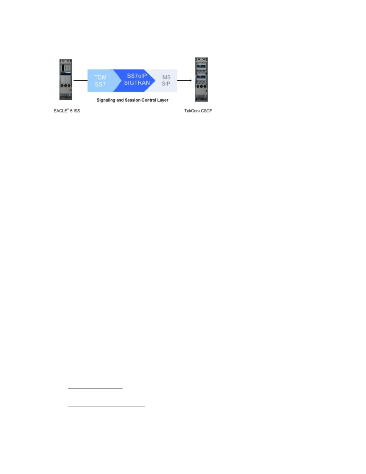
Figure 1-1. Transition from SS7 to IMS
This document examines the reasons for transitioning to an SS7-over-IP (SSoIP) network, the considerations that
go into planning and dimensioning, and helpful information for implementing the network. This document does
not attempt to provide a beginning-to-end solution for such a transition; contact your Tekelec Sales Representative
to discuss your specific needs.
Audience
The audience for this document are Tekelec departments affected by the development, sale, or service of
SIGTRAN-related products, as well as Tekelec customers that require an overview of SS7-over-IP networks,
SIGTRAN, and products that are part of the Tekelec solution.
Updates for this Release
The IP Signaling Gateway (IPSG) feature is introduced in release 38.0. This feature provides a signaling gateway
(SG) application as an alternative to the IPLIM and IPGW applications (the IPLIM and IPGW applications continue
to be supported). The IPSG feature can run the M2PA and M3UA protocols simultaneously on the same card, and
supports ANSI, ITU-N or ITUN-24, and ITU-I simultaneously on one card and one association. The SUA protocol
is not supported by this feature The IPSG feature runs on the E5-ENET cards only.
As part of the IPSG feature, the IPGWx Signaling TPS FAK is removed. Since customers will no longer be required
to purchase IP Signaling TPS, they can allocate as much SLKTPS as needed (up to the card limit) to accommodate
failover scenarios. The Eagle OAM enforces a system-wide IP Signaling TPS limit of 500,000 TPS provisioned
for IPGWx and IPSG link sets.
The IPSG feature works in conjunction with the SIGTRAN Measurements Phase 1 feature. The IPVSHL and the
IPVL link classes introduced in the SIGTRAN feature are used for the M2PA and the M3UA links, respectively.
See the EAGLE 5 ISS 38.0 Feature Manual for more information on these new features.
Manual organization
The manual is organized into these chapters:
•Chapter 1 Introduction provides the purpose of this document, the targeted audience, how the manual is
organized, and Tekelec contact information.
•Chapter 2 SS7-over-IP networks describes the concept of an SS7- over-IP network and the protocols it uses,
the opportunities it provides now and what it means for future directions. This section takes the reader from
current TDM limitations, to the role of SIGTRAN, to the reasoning of why and when to transition to an
SS7-over-IP network.
Audience SIGTRAN User Guide
1-2 910-5346-001 Revision A, September 2008

•Chapter 3 Tekelec solutions describes how Tekelec products are a part of the SS7-over-IP solution. This
section describes how the EAGLE 5 Integrated Signaling System (ISS) functions as a gateway to internet
networks; and the Integrated Application Solution (IAS) , which provides several network management
and performance tools including IP traffic monitoring through the Integrated Message Feeder (IMF) .
•Chapter 4 Transition planning provides a guideline on how to prepare for a transition to an SS7-over-IP
network.
•Chapter 5 Dimensioning describes dimensioning issues and calculations required to maximize the efficiency
of the new network. This section addresses scalability, redundancy schemes, throughput calculations for
both normal and failover mode, LAN /WAN considerations, and retransmission concepts.
•Chapter 6 Implementation ” provides hardware information, high-level configuration steps for the
IPLIMx and IPGWx applications, how to refine timers and parameters after the installation, and high-
level system verification steps.
•Chapter 7 Troubleshooting offers troubleshooting procedures based on symptoms occurring in the network.
•Appendix A Additional Deployment Scenarios provides other possible deployment scenarios.
•Appendix B References lists Tekelec-internal and external references used in this manual. Customers
requiring access to Tekelec-internal references should contact their Sales Representative to obtain equivalent
information. This section also provides the location of customer documentation on the Tekelec Customer
Support site.
•“Glossary” defines both acronyms and terminology used in this manual.
Manual conventions
Several conventions are used in this document. While certain acronyms are standard in the telecom industry and
are understood by most readers, this document treats network components and feature name as proper names and
spells out their names to improve the reading of this document.
For some process descriptions, figures or tables are displayed at the beginning of the process to allow the reader
to follow most of the process on the same page. This convention is identified with each process.
Tekelec customer documentation is transitioning to sentence-style section headings to accommodate new
documentation development technologies.
Where “end points” are mentioned, the full range is included: Service Switching Points (SSPs)
, Signaling Control
Points (SCPs), Home Locator Registers (HLRs), Short Message Service Centers (SMSCs) .
Documentation Admonishments
Admonishments are icons and text throughout this manual that alert the reader to assure personal safety, to
minimize possible service interruptions, and to warn of the potential for equipment damage.
Table 1-1. Admonishments
DANGER:
SIGTRAN User Guide Manual conventions
910-5346-001 Revision A, September 2008 1-3

(This icon and text indicate the possibility of personal injury.)
WARNING:
(This icon and text indicate the possibility of equipment damage.)
CAUTION:
(This icon and text indicate the possibility of service interruption.)
Customer Care Center
The Tekelec Customer Care Center offers a point of contact for product and service support through highly trained
engineers or service personnel. The Tekelec Customer Care Center is available 24 hours a day, 7 days a week at
the following locations:
•Tekelec, USA
Phone:
+1 888 367 8552 (US and Canada only)
+1 919 460 2150 (international)
Email: [email protected]
• Tekelec, Europe
Phone: +44 1784 467804
Email:[email protected]
When a call is received, a Customer Service Report (CSR) is issued to record the request for service. Each CSR
includes an individual tracking number.
After a CSR is issued, the Customer Care Center determines the classification of the trouble. If a critical problem
exists, emergency procedures are initiated. If the problem is not critical, information regarding the serial number
of the system, COMMON Language Location Identifier (CLLI), initial problem symptoms (includes outputs and
messages) is recorded. A primary Customer Care Center engineer is also assigned to work on the CSR and provide
a solution to the problem. The CSR is closed when the problem is resolved.
Emergency Response
In the event of a critical service situation, emergency response is offered by the Tekelec Customer Care Center 24
hours a day, 7 days a week. The emergency response provides immediate coverage, automatic escalation, and other
features to ensure that the critical situation is resolved as rapidly as possible.
A critical situation is defined as a problem with an EAGLE 5 ISS that severely affects service, traffic, or
maintenance capabilities, and requires immediate corrective action. Critical problems affect service and/or system
operation resulting in:
• A total system failure that results in loss of all transaction processing capability
• Significant reduction in system capacity or traffic handling capability
Customer Care Center SIGTRAN User Guide
1-4 910-5346-001 Revision A, September 2008

• Loss of the system’s ability to perform automatic system reconfiguration
•Inability to restart a processor or the system
• Corruption of system databases that requires service affecting corrective actions
• Loss of access for maintenance or recovery operations
• Loss of the system ability to provide any required critical or major trouble notification
Any other problem severely affecting service, capacity/traffic, billing, and maintenance capabilities may be defined
as critical by prior discussion and agreement with the Tekelec Customer Care Center.
Related Publications
For information about additional publications that are related to this document, refer to the Related Publications
document. The Related Publications document is published as a part of the Release Documentation and is also
published as a separate document on the Tekelec Customer Support Site.
Documentation Availability, Packaging, and Updates
Tekelec provides documentation with each system and in accordance with contractual agreements. For General
Availability (GA) releases, Tekelec publishes a complete EAGLE 5 ISS documentation set. For Limited
Availability (LA) releases, Tekelec may publish a documentation subset tailored to specific feature content or
hardware requirements. Documentation Bulletins announce a new or updated release.
The Tekelec EAGLE 5 ISS documentation set is released on an optical disc. This format allows for easy searches
through all parts of the documentation set.
The electronic file of each manual is also available from the Tekelec Customer Support site. This site allows for
24-hour access to the most up-to-date documentation.
Printed documentation is available for GA releases on request only and with a lead time of six weeks. The printed
documentation set includes pocket guides for commands and alarms. Pocket guides may also be ordered as a set
or individually. Exceptions to printed documentation are:
• Hardware or Installation manuals are printed only without the linked attachments found in the electronic
version of the manuals.
• The Release Notice is available only on the Customer Support site.
NOTE: Customers may print a reasonable number of each manual for their own use.
Documentation is updated when significant changes are made that affect system operation. Updates resulting from
Severity 1 and 2 PRs are made to existing manuals. Other changes are included in the documentation for the next
scheduled release. Updates are made by re-issuing an electronic file to the customer support site. Customers with
printed documentation should contact their Sales Representative for an addendum. Occasionally, changes are
communicated first with a Documentation Bulletin to provide customers with an advanced notice of the issue until
officially released in the documentation. Documentation bulletins are posted on the Customer Support site and
can be viewed per product and release.
SIGTRAN User Guide Related Publications
910-5346-001 Revision A, September 2008 1-5

Locate Product Documentation on the Customer Support Site
To view or download product documentation, log into the Tekelec Customer Support site at:
https://support.tekelec.com/index.asp
1. Log in with your user name and password. (Click on Need an Account? if you need to register).
2. Select EAGLE from the Product Support menu.
3. Select the release number from the Release menu.
4. Locate the Notices section to view the latest Feature Notice.
5. Locate the Manuals section to view all manuals applicable to this release.
The documentation is listed in alphabetical order by the manual name. Only the first three manuals display.
Click more… to see the remaining manuals.
6. Locate the latest revision of the manual name.
Confirm the release number and last available revision.
Select the 936-xxxx-x01 part number to download the complete documentation set with all linked files.
NOTE: The electronic file for this part number is quite large.
7. To view a manual, double-click the manual name.
8. To download a manual, right-click and select Save Target As.
NOTE: Customers may print a reasonable number of each manual for their own use.
Locate Product Documentation on the Customer
Support Site SIGTRAN User Guide
1-6 910-5346-001 Revision A, September 2008

2
SS7-over-IP networks
SS7-over-IP networks overview ......................................................................................................................... 2-1
SS7 limitations .................................................................................................................................................... 2-2
Role of SIGTRAN .............................................................................................................................................. 2-2
SCTP (Stream Control Transmission Protocol) .......................................................................................... 2-3
M2PA (MTP2 User Peer-to-Peer Adaptation Layer) protocol ................................................................... 2-4
M3UA (MTP Level 3 User Adaptation Layer) protocol ............................................................................. 2-5
SUA (SCCP User Adaptation) protocol ...................................................................................................... 2-6
SS7-over-IP signaling transport .......................................................................................................................... 2-6
From SS7 message to IP packet .................................................................................................................. 2-7
Communication inside the Wide Area Network (WAN) ............................................................................ 2-7
Reasons to transition to an SS7-over-IP SIGTRAN network ............................................................................. 2-8
Cost effectiveness ........................................................................................................................................ 2-8
Increased capacity ....................................................................................................................................... 2-9
Integration ................................................................................................................................................... 2-9
Type of network change ................................................................................................................................... 2-10
Dedicated network versus converged IP networkt .................................................................................... 2-10
Replacement versus expansion .................................................................................................................. 2-10
Diversity .................................................................................................................................................... 2-11
When to transition to an SS7-over-IP SIGTRAN network .............................................................................. 2-11
SS7-over-IP networks overview
An SS7-over-IP network consists of a traditional SS7 network that can integrate IP-enabled or all-IP devices with
protocols defined by the Internet Engineering Task Force (IETF) standards organization.
SS7-over-IP signaling primarily addresses the transport aspect of SS7. Call-control services and other types of
services, therefore, can continue to be offered and deployed without concern for the method of interconnection.
The method of service implementation, however, remains dependent on the particular network element chosen to
support the service rather than the transport chosen.
This section looks at the limitations of the traditional SS7 network and its network components, the role of
SIGTRAN protocols, the purpose of SS7-over-IP networks, the advantages of transitioning to this network, and
when it is time to consider transitioning.
910-5346-001 Revision A, September 2008 2-1

SS7 limitations
SS7 is a signaling network (data traffic) protocol used to send and receive signaling messages between Signaling
End Points over dedicated signaling links. Operators deploy SS7 services over a dedicated network of 56- or 64-
kbps Time Division Multiplexed (TDM) lines, or utilize high-speed T1 (1.5 Mbps) or E1 (2.048 Mbps) lines. SS7
uses centralized databases and services, achieves reliable connections through
network management, and is secure
because of its isolation from end users and the dedicated network. SS7 signaling is mature with standards and a
rich feature set, and offers these advantages to both wireline and wireless services.
However, SS7 limitations in scalability, bandwidth, and network availability slow network growth and
opportunities to participate in new IP services:
• Scalability is limited by 16-link linksets consisting of 64 kbps transport
Up to 16 links may be grouped into one circuit, or linkset. Adjacent network elements, such as Signal
Transfer Points (STPs) and Service Control Points (SCPs), may be connected by no more than one linkset.
The protocol further recommends that links and linksets are configured to no more than 40% of their
maximum capacity, so that the alternate path can carry the full load of messages during failover.
• Bandwidth
A traditional SS7 message size is limited to about 272 octets. E1/T1 links allow the transmission of larger
messages, but not without originating, routing, or end points supporting either large messages or message
segmentation.
A bandwidth of 56 kbps or 64 kbps per link and dedicated links reduce flexibility and increase cost
significantly when creating sufficient bandwidth for new service applications. In a TDM network, entire
transmission segments must be reserved for each call, even if the TDM connection is idle.
TDM-based SS7 is continuing to evolve, but slowly. Instead, wireline and wireless operators are looking to IP
solutions.
Role of SIGTRAN
SIGTRAN is a working group of the IETF , addressing packet -based Public Switched Telephone Network
(PSTN) signaling over IP networks. A set of signaling transport protocols has been developed out of the group’s
work. For the purposes of this document, the protocols are collectively called the “SIGTRAN” protocols or suite.
The SIGTRAN architecture used by Tekelec includes the following protocols. The figure shows their location
in the protocol stack:
• Stream Control Transmission Protocol (SCTP); RFC 4960
• MTP2 User Peer-to-Peer Adaptation Layer (M2PA) protocol; RFC 4165
• MTP3 User Adaptation Layer (M3UA) protocol; RFC 4666
• SCCP User Adaptation Layer (SUA) protocol; RFC 3868
SS7 limitations SIGTRAN User Guide
2-2 910-5346-001 Revision A, September 2008
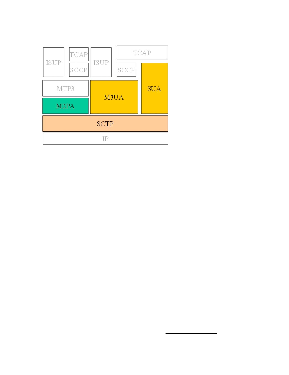
Figure 2-1. SIGTRAN protocols used by Tekelec
SCTP (Stream Control Transmission Protocol)
SCTP is a new reliable transport protocol that operates on top of a connectionless packet network such as IP,
and operates at the same layer as TCP. It establishes a connection between two endpoints, called an association,
for transmission of user messages. To establish an association between SCTP endpoints , one endpoint provides
the other with a list of its transport addresses (one or more IP addresses in combination with an SCTP port).
These transport addresses identify the addresses that will send and receive SCTP packets. SCTP was developed
to eliminate deficiencies in TCP and offers acknowledged, error-free, non-duplicated user data transport.
IP signaling traffic is usually composed of many independent message sequences between many different signaling
endpoints. SCTP allows signaling messages to be independently ordered within multiple streams (unidirectional
logical channels established from one SCTP end point to another) to ensure in-sequence delivery between
associated end points. By transferring independent message sequences in separate SCTP streams, it is less likely
that the retransmission of a lost message will affect the timely delivery of other messages in unrelated sequences
(called head-of-line blocking). Because TCP does enforce head-of-line blocking, the SIGTRAN Working Group
recommends SCTP rather than TCP for the transmission of signaling messages over IP networks.
Security
SCTP provides certain transport-related security features, such as resistance against blind denial of service attacks,
masquerades, or improper monopolization of services.
SIGTRAN protocols do not define new security mechanisms, as the currently available security protocols provide
the necessary mechanisms for secure transmission of SS7 messages over IP networks.
Tekelec deviations
The following sections summarize the most important deviations from the IETF RFCs that Tekelec has made.
Refer to the Tekelec protocol compliance matrices for details; see Tekelec internal references . Contact your Sales
Representative for access to the information contained in these documents.
SIGTRAN User Guide Role of SIGTRAN
910-5346-001 Revision A, September 2008 2-3

SCTP multiple streams
There are several architectural issues regarding the use of multiple streams as described in the SCTP protocol. The
issues include:
•Synchronization between data streams
• Synchronization from control stream to data streams
• Load-sharing implementation based on SLS across streams, either within a connection or across all the
connections in an Application Server
Since the underlying SS7 network is connectionless, a stringent requirement for missequenced messages has
been set because it is often easier to recover from the loss of a message by a time-out than from one message
delivered out-of-sequence. The Message Transfer Part (MTP) is able to maintain a high probability of
message sequencing. This is ensured by the MTP user, which generates a value for a Signaling Link Selection
(SLS) field as a parameter for each message. As the message is routed through the network, wherever there
is a choice to be made between alternate routes, the link selection is made based on the SLS value in the
message.
• Connection behavior when a stream becomes congested
A lack of consensus on the IETF SIGTRAN mailing list regarding these issues resulted in Tekelec supporting a
maximum of two streams: a control stream and a data stream.
SCTP timer
Based on experiences in the field, Tekelec has deviated from some RFC-recommended timer settings, especially
related to retransmission, to better accommodate signaling networks.
The Tekelec default mode for the retransmission timer (RMODE) is linear, whereas the RFC-recommended timer
setting is exponential. Tekelec makes both settings available through configuring an association to use either the
Linear (LIN) or the exponential (RFC) method. For more information about both modes and the timer settings,
see “SCTP timers” .
M2PA (MTP2 User Peer-to-Peer Adaptation Layer) protocol
M2PA is used primarily to replace B-, C-, and D-links. When used with A-links, M2PA connects to Service
Switching Points , Signaling Control Points , Home Locator Registers and other endpoints. M2PA is a direct
replacement for channelized TDM circuits because it has specific controls for assurance of in-sequence delivery
of messages. As such, M2PA is needed to connect points that pass call-related data that is time-sensitive, such
as ISUP calling data.
Congestion procedures conform to those specified by the ANSI/ITU standards. The M2PA protocol can coexist
in a linkset with other link types such as low-speed links and ATM high speed links. When using other link types,
the throughput will always match the lowest-speed link in the linkset.
Tekelec implemented the M2PA protocol through its IPLIMx application. For more information on the IPLIMx
application, see IPLIMx, IPGWx and IPSG applications .
Role of SIGTRAN SIGTRAN User Guide
2-4 910-5346-001 Revision A, September 2008
Other manuals for EAGLE 5
12
Table of contents
Popular Conference System manuals by other brands

Bosch
Bosch DICENTIS user manual

StarLeaf
StarLeaf Group Telepresence 3351 user guide

BMW Motorrad
BMW Motorrad Communication system operating instructions

Optimus
Optimus EDC-1000 SERIES instruction manual

PictureTel
PictureTel Venue-2000 Administrator's guide

Bosch
Bosch DCN-CONCM Concentus Quick reference guide

LEGRAND
LEGRAND C2G 29973 manual

FONESTAR
FONESTAR SCF-250 instruction manual

Sailor
Sailor C4951WP Operating and installation instructions

Polycom
Polycom RealPresence Trio 8500 user guide

Advanced Wireless Communications
Advanced Wireless Communications AWR-CB2200 Operator's manual

JTS
JTS CS-120 Series manual


