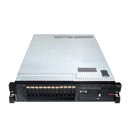
Tekelec 1100 User manual

Tekelec 1100 Application Server
Hardware Manual
910-2969-001 Revision K
June 2009

Copyright 2009 Tekelec
All Rights Reserved
Printed in USA
Notice
Information in this documentation is subject to change without notice. Unauthorized use, copying, or
translation of this documentation can result in civil or criminal penalties.
Any export of Tekelec products is subject to the export controls of the United States and the other
countries where Tekelec has operations.
No part of this documentation may be reproduced, translated, or transmitted in any form or by any
means, electronic or mechanical, including photocopying or recording, for any purpose without the
express written permission of an authorized representative of Tekelec.
Other product names used herein are for identification purposes only, and may be trademarks of their
respective companies.
RoHS 5/6 - As of July 1, 2006, all products that comprise new installations shipped to European Union
member countries will comply with the EU Directive 2002/95/EC "RoHS" (Restriction of Hazardous
Substances). The exemption for lead-based solder described in the Annex will be exercised. RoHS 5/6
compliant components will have unique part numbers as reflected in the associated hardware and
installation manuals.
WEEE - All products shipped to European Union member countries comply with the EU Directive
2002/96/EC, Waste Electronic and Electrical Equipment. All components that are WEEE compliant will
be appropriately marked. For more information regarding Tekelec's WEEE program, contact your sales
representative.
Trademarks
The Tekelec logo, EAGLE, G-Flex, G-Port, IP7, IP7 Edge, and IP7 Secure Gateway are registered
trademarks of Tekelec. TekServer, A-Port, EAGLE 5 ISS, and V-Flex are trademarks of Tekelec. All other
trademarks are the property of their respective owners.
Patents
This product is covered by one or more of the following U.S. and foreign patents:
U.S. Patent Numbers:
5,732,213; 5,953,404; 6,115,746; 6,167,129; 6,324,183; 6,327,350; 6,456,845; 6,606,379; 6,639,981; 6,647,113;
6,662,017; 6,735,441; 6,745,041; 6,765,990; 6,795,546; 6,819,932; 6,836,477; 6,839,423; 6,885,872; 6,901,262;
6,914,973; 6,940,866; 6,944,184; 6,954,526;6,954,794; 6,959,076; 6,965,592; 6,967,956; 6,968,048; 6,970,542;
6,987,781; 6,987,849; 6,990,089; 6,990,347; 6,993,038; 7,002,988; 7,020,707; 7,031,340; 7,035,239; 7,035,387;
7,043,000; 7,043,001; 7,043,002; 7,046,667; 7,050,456; 7,050,562; 7,054,422; 7,068,773; 7,072,678; 7,075,331;
7,079,524; 7,088,728; 7,092,505; 7,108,468; 7,110,780; 7,113,581; 7,113,781; 7,117,411; 7,123,710; 7,127,057;
7,133,420; 7,136,477; 7,139,388; 7,145,875; 7,146,181; 7,155,206; 7,155,243; 7,155,505; 7,155,512; 7,181,194;
7,190,702; 7,190,772; 7,190,959; 7,197,036; 7,206,394; 7,215,748; 7,219,264; 7,222,192; 7,227,927; 7,231,024;
7,242,695; 7,254,391; 7,260,086; 7,260,207; 7,283,969; 7,286,516; 7,286,647; 7,286,839; 7,295,579; 7,299,050;
7,301,910; 7,304,957; 7,318,091; 7,319,857; 7,327,670
Foreign Patent Numbers:
EP1062792; EP1308054; EP1247378; EP1303994; EP1252788; EP1161819; EP1177660; EP1169829; EP1135905;
EP1364520; EP1192758; EP1240772; EP1173969; CA2352246
Ordering Information
Your Tekelec Sales Representative can provide you with information about how to order additional
discs.

Table of Contents
Chapter 1: About This Manual ....................................................1
Introduction........................................................................................................................2
Where to Find Information ..............................................................................................2
Programs Needed to View Linked Documents ................................................4
Documents That Show How to Perform a Procedure......................................4
Installation Documents.........................................................................................4
Applications Documents.......................................................................................5
Related Publications..........................................................................................................5
Documentation Availability, Packaging, and Updates................................................5
Locate Product Documentation on the Customer Support Site..................................6
Documentation Admonishments....................................................................................6
Customer Care Center.......................................................................................................7
Problem Report (PR)..............................................................................................9
Emergency Response...........................................................................................10
Hardware Repair and Return.........................................................................................11
Repair and Return Shipping Instructions.........................................................12
Returning a Crate.................................................................................................13
How to LocateT1100 AS Part Numbers............................................................14
Chapter 2: Safety and Pre-Installation Requirements............29
Introduction......................................................................................................................30
Safety Information...........................................................................................................30
Regulatory Compliance and Certification....................................................................32
Pre-Installation Site Requirements................................................................................33
Generic Site Requirements..................................................................................33
Grounding and Power Requirements...............................................................35
Chapter 3: T1100 AS Hardware System Overview..................39
Introduction......................................................................................................................40
T1100 AS Hardware System...........................................................................................40
T1100 AS Hardware Features.........................................................................................42
Breaker Panel....................................................................................................................46
Breaker Panel LEDs.............................................................................................47
Breaker Panel Power............................................................................................49
iii
910-2969-001 Revision K, June 2009

Power Distribution Units................................................................................................50
Ethernet Switches or Hubs.............................................................................................50
Console Servers................................................................................................................51
Chapter 4: How to Install aT1100 AS Frame.............................53
Introduction......................................................................................................................54
How to Unpack the T1100 AS Frame and Conduct Inventory.................................54
How to Install a T1100 AS Frame..................................................................................54
Recommended Tools...........................................................................................55
How to Prepare the Floor for Heavy Duty Frames.........................................55
How to Anchor the HD Frame to the Floor.....................................................57
How to Anchor to Overhead Rack of HD Frame............................................66
How to Cable a T1100 AS Frame...................................................................................67
Chapter 5: How to Install Hardware in an Existing
Frame............................................................................................69
Introduction......................................................................................................................70
How to Unpack and Conduct Inventory......................................................................70
How to Unpack a T1100 AS Unit and Conduct Inventory............................70
How to Install an Individual T1100 AS Unit...............................................................71
How to Cable Components Added to Existing Frames.............................................81
How to Cable a T1100 AS Unit Added to an Existing Heavy Duty
Frame...............................................................................................................81
How to Cable a T1100 AS Installed in Customer-Provided Frame..............81
Chapter 6: Post Installation Procedures....................................83
Introduction......................................................................................................................84
How to Connect Frame Ground and Logic Ground...................................................84
How to Ground in a DC Environment.............................................................85
How to Ground the Logic Connector in a AC Environment.........................92
Post-Installation Checklist..............................................................................................94
How to Power Up............................................................................................................96
How to Power Up a T1100 AS Unit in an AC Environment.........................96
How to Change Passwords............................................................................................97
Chapter 7: Field Replaceable Units............................................99
Introduction....................................................................................................................100
Safety Information.............................................................................................100
910-2969-001 Revision K, June 2009
iv

T1100 AS Hardware System FRUs and Part Numbers................................102
T1100 AS FRUs...................................................................................................102
Tools Required...............................................................................................................104
How to Replace a Console Server, Router, Ethernet Switch, or Hub ....................104
How to Access T1100 AS FRUs....................................................................................105
How to SlideT1100 AS Chassis Out from Frame...........................................106
How to Slide T1100 AS Chassis Back into Frame..........................................107
How to Remove T1100 AS Chassis from a Frame.........................................108
How to Return a T1100 AS Chassis to the Frame..........................................110
How to ReplaceT1100 AS FRUs...................................................................................113
How to Replace the Air Filters.........................................................................113
How to Replace the Rectangular Fan Assembly...........................................115
How to Replace the Square Fan Assembly....................................................116
How to Replace Hard Disk Drive Assemblies...............................................118
How to Replace Removable Media Disk Drives (CD/DVD)......................123
How to Replace a Power Supply Module......................................................128
How to Replace PCI Cards...............................................................................129
How to Replace aT1100 AS Chassis FRU.......................................................134
Appendix A: T1100 AS Hardware Feature Information......137
Introduction....................................................................................................................138
Hardware Components.................................................................................................138
Interfaces.........................................................................................................................138
Out of Band Management Card...................................................................................140
Electrical Features..........................................................................................................140
Mechanical Design.........................................................................................................140
T1100 AS Diagnostics....................................................................................................142
Appendix B: ELAP or EPAP Network Integration................143
Introduction....................................................................................................................144
Network Overview........................................................................................................144
Customer-Supplied Information.................................................................................145
IP Address Assignment.................................................................................................146
Netmask and Broadcast................................................................................................148
Network Interface Functions........................................................................................149
Network Assumptions..................................................................................................150
Network Configuration.................................................................................................151
Firewall and Router Filtering Considerations...........................................................151
Serial Communication...................................................................................................153
Modems ..............................................................................................................154
v
910-2969-001 Revision K, June 2009

Printers................................................................................................................155
Tip Utility (EAGLE Only..................................................................................155
Glossary............................................................................................................157
910-2969-001 Revision K, June 2009
vi

List of Figures
Figure 1: T1100 AS Chassis Front View....................................................................................15
Figure 2: T1100 AS Front Top Cover screws............................................................................15
Figure 3: Fan Part number labels...............................................................................................16
Figure 4: Removable Media Disk Drive Assembly Part Label..............................................17
Figure 5: T1100 AS Chassis Front View....................................................................................17
Figure 6: T1100 AS Front Top Cover screws............................................................................18
Figure 7: CD/DVD label location..............................................................................................18
Figure 8: T1100 AS Chassis Label Locations............................................................................19
Figure 9: Base Unit/Hard Disk Label onT1100 AS Chassis...................................................19
Figure 10: T1100 AS front fascia open with hard drive locations.........................................20
Figure 11: Hard disk label locations..........................................................................................21
Figure 12: T1100 AS Chassis Label Locations..........................................................................22
Figure 13: PCI Slots Label onT1100 AS Chassis.......................................................................22
Figure 14: T1100 AS Chassis Front View..................................................................................23
Figure 15: Frame Identification Label.......................................................................................24
Figure 16: T1100 AS Chassis Front View..................................................................................25
Figure 17: Base Unit/Hard Disk Label onT1100 AS Chassis.................................................25
Figure 18: Memory Label onT1100 AS Chassis.......................................................................26
Figure 19: PCI Card Label onT1100 AS Chassis......................................................................27
Figure 20: European Directives CE Mark.................................................................................32
Figure 21: Combined UL and GS Mark....................................................................................32
Figure 22: UL-Demko Mark........................................................................................................32
Figure 23: Combined UL Mark for the United States and Canada.......................................32
Figure 24: Door Grounding Strap Placement..........................................................................36
Figure 25: T1100 AS Hardware System in DC Environment.................................................41
Figure 26: Tekelec 1100 AS Chassis...........................................................................................42
Figure 27: Interior View ofT1100 AS Chassis...........................................................................42
Figure 28: Rear I/O Panel...........................................................................................................44
Figure 29: T1100 AS Status Indicators.......................................................................................44
Figure 30: T1100 AS with Side Cable Management Arms ....................................................46
Figure 31: Front of Breaker Panel..............................................................................................46
Figure 32: Breaker Panel LEDs...................................................................................................47
Figure 33: Front and rear of AC power distribution unit......................................................50
Figure 34: Floor Marking Template for HD Frame.................................................................56
Figure 35: Anchor Assembly for Slab Floors...........................................................................57
Figure 36: Anchor Installation of HD Frame into Slab Floor.................................................59
Figure 37: Anchor Assembly for Raised Floor Over Concrete..............................................60
vii
910-2969-001 Revision K, June 2009

Figure 38: Anchoring on Raised Floor Over Concrete Slab...................................................61
Figure 39: Anchor Assembly for Use with Support Channel................................................63
Figure 40: Anchoring Frame to Raised Floor with Support Channel...................................64
Figure 41: Anchor Assembly for Support Channel with Spring Nut...................................65
Figure 42: Anchoring Frame Using Support Channel/Spring Nut......................................65
Figure 43: HD Frame with Overhead Rack..............................................................................66
Figure 44: Slide Assembly...........................................................................................................71
Figure 45: Slide Assembly Extended View..............................................................................72
Figure 46: Slide Assembly Inner Member Roller Side View .................................................73
Figure 47: Frame Adapter Bracket Expanded..........................................................................74
Figure 48: Frame Adapter Brackets and Slide Assemblies....................................................74
Figure 49: Slide Assembly Outer Member...............................................................................75
Figure 50: Slide Assembly Detail Left Side From Rear...........................................................75
Figure 51: Slide Assembly Inner Member Mounting ............................................................76
Figure 52: Detail of a Side Cable Management Arm..............................................................77
Figure 53: Side Cable Management Arm Installation (T1000 AS shown)...........................78
Figure 54: T1100 AS Rear Detail................................................................................................79
Figure 55: Frame Mounting Detail............................................................................................80
Figure 56: Frame Ground Cable Routes in DC Environment................................................86
Figure 57: Frame Ground Cable Attachment Locations in DC Environment ....................87
Figure 58: Chassis Ground Cable Attachment Location in DC Environment....................88
Figure 59: Logic Ground Cable Routes in DC Environment.................................................90
Figure 60: Frame and Logic Ground Cable Attachment Locations......................................91
Figure 61: Logic Ground Cable Route in AC Environment...................................................92
Figure 62: T1100 AS Chassis Front View................................................................................106
Figure 63: Chassis Retention Hardware.................................................................................109
Figure 64: Right Slide Assembly Mounting and Retention Bracket...................................111
Figure 65: T1100 AS Chassis Rear View.................................................................................112
Figure 66: Inside view ofT1100showing fan filters...............................................................114
Figure 67: Front Top Cover Removal - Screw Locations......................................................115
Figure 68: Inside view ofT1100showing square fan assembly............................................117
Figure 69: Inside view ofT1100showing hard drive locations.............................................120
Figure 70: Hard drive removal.................................................................................................121
Figure 71: T1100 AS Chassis Label Locations........................................................................122
Figure 72: Hard Disk Drive Label onT1100 AS Chassis.......................................................122
Figure 73: Disk Drive label locations (fans removed)...........................................................122
Figure 74: Inside view ofT1100showing CD/DVD drive location.....................................124
Figure 75: Front Top Cover Removal - Screw Locations......................................................125
Figure 76: CD/DVD inside bracket screw location..............................................................126
Figure 77: CD/DVD chassis screws........................................................................................126
Figure 78: Removable Media Disk Drive Cables (drives removed)...................................127
910-2969-001 Revision K, June 2009
viii

Figure 79: Rotate lock ring down to disengage power supply module.............................128
Figure 80: PCI Card Part Label................................................................................................130
Figure 81: PCI Slots Label.........................................................................................................130
Figure 82: Chassis Rear Top Cover Views..............................................................................132
Figure 83: PCI Cards and Slot Assignments..........................................................................132
Figure 84: Left Slide Member Mounting................................................................................135
Figure 85: MPS Network Connections, Netra........................................................................144
Figure 86: MPS Network Connections, T1100 AS, T1100 AS..............................................145
ix
910-2969-001 Revision K, June 2009

List of Tables
Table 1: Manual Organization......................................................................................................2
Table 2: Admonishments..............................................................................................................6
Table 3: Basic RMA Types..........................................................................................................11
Table 4: RMA Reasons for Return.............................................................................................11
Table 5: Space Requirements......................................................................................................34
Table 6: Tekelec 1100 AS Chassis Dimensions and Weight...................................................45
Table 7: Breaker Panel LED Settings.........................................................................................47
Table 8: Post-Installation Checklist...........................................................................................94
Table 9: T1100 AS Field Replaceable Units and Part Numbers...........................................103
Table 10: Basic Interfaces .........................................................................................................139
Table 11: Optional Interfaces (on PCI Cards)........................................................................139
Table 12: IP Address for the DSM Network...........................................................................146
Table 13: IP Address for the Sync Network...........................................................................147
Table 14: EAGLE 5 ISS IP Addresses......................................................................................147
Table 15: Interface Functions Required for MPS...................................................................149
Table 16: Interface Functions Required for MPS...................................................................151
Table 17: Serial Port Assignments for MPS Servers A and B...............................................154
910-2969-001 Revision K, June 2009
x

Chapter
1
About This Manual
This chapter describes how to use the manual,
where to find other information about this
Topics:
•Introduction.....2 product, and how to contact the Customer Care
Center on page 7.
•Where to Find Information .....2
•Related Publications.....5
•Documentation Availability, Packaging, and
Updates.....5
•Locate Product Documentation on the Customer
Support Site.....6
•Documentation Admonishments.....6
•Customer Care Center.....7
•Hardware Repair and Return.....11

Introduction
AT1100 AS hardware system consists of one or moreT1100 AS (with applications loaded) and any
additional hardware (such as hubs, switches, or power distribution equipment) needed to support
the applications.
Note: This manual includes links to documents that are specific to a given product, depending
on which product CD this manual is viewed. Although the manual is the same on CDs for various
products, the linked documents are different on different product CDs. For more information
about linked documents, see Where to Find Information on page 2.
T1100 AS hardware systems are delivered with applications already loaded.
For more information aboutT1100 AS hardware systems in AC and DC environments, see T1100
AS Hardware System Overview on page 39
Each time this manual is published, the revision level is changed. For example, the first time this
manual is published, it uses Revision A; the second time it is published, it uses Revision B.
Where to Find Information
Table 1: Manual Organization on page 2 shows how this manual is organized.
Table 1: Manual Organization
DescriptionChapter Number and Title
Describes how to use the manual, where to find
other information, how to contact Customer Care
About This Manual on page 1
Center on page 7, and Hardware Repair and
Return on page 11.
Lists general safety instructions that readers
should be familiar with, and lists site
Safety and Pre-Installation Requirements on page
29
requirements that should be verified before
installingT1100 AS hardware systems.
Presents an overview of the various hardware
components that can be included inT1100 AS
hardware systems.
T1100 AS Hardware System Overview on page 39
Describes how to install a heavy duty frame
which is delivered from manufacturing
How to Install aT1100 AS Frame on page 53
withT1100 AS units mounted in a heavy-duty
frame for use in a DC environment.
910-2969-001 Revision K, June 2009
2
Hardware ManualAbout This Manual

DescriptionChapter Number and Title
Describes how to install an individualT1100 AS
unit into a frame that has already been installed.
This chapter covers both:
How to Install Hardware in an Existing Frame on
page 69
•Adding aT1100 AS unit into a heavy duty
frame that already contains from 1 to 4T1100
AS units in a DC environment
•Installing a singleT1100 AS unit into a
customer’s frame in an AC environment.
Presents a post-installation checklist and
instructions on how to verify voltage and to
power-up the system.
Post Installation Procedures on page 83
Describes the components of aT1100 AS
hardware system that can be replaced in the
Field Replaceable Units on page 99
field, and includes procedures for replacing
each type of field-replaceable unit (FRU).
Describes in greater detail some of the hardware
features of theT1100 AS chassis.
T1100 AS Hardware Feature Information on page
137
Provides network integration information for
the Multi-Purpose Server (MPS) systems
ELAP or EPAP Network Integration on page 143
This manual is delivered on a multi-media disk (DVD) that also contains the following
documentation (these documents can also be accessed from the introductory page of the
documentation DVD.
•The DVD contains linked documents shown in the following sections. To display one of these
documents from within this document, click anywhere in the highlighted area. For information
about software needed to open these links, see Programs Needed to View Linked Documents on
page 4.
•Optionally, the DVD may also contain application documentation, which describes the
environment in which theT1100 AS hardware system runs as well as provides information
about the application.
Note: Documentation aboutT1100 AS hardware components (such as breaker panels or Ethernet
switches) that are supplied by other companies is shipped with theT1100 AS hardware system.
When unpacking a frame or individual components, be sure to obtain this documentation and
store it where it can be accessed later.
):
3
910-2969-001 Revision K, June 2009
About This ManualHardware Manual

Programs Needed to View Linked Documents
To view the linked documents, the workstation on which this manual is being viewed needs to
have the following programs:
•Most of the linked documents are in Portable Document Format (PDF), which has a file type
of .pdf. PDF is also the format of this manual. When a PDF link is clicked, the linked document
is opened in the same window as this manual. To return to this manual, click the Back button
on the PDF display window.
•A document with a .doc file type can be viewed with Microsoft®Word. The linked document
may open in a minimized window.
•A document with an .mpg file type can be viewed with a variety of video programs. Two
commonly used programs are:
•Microsoft Windows®Media Player (this program is usually included with Microsoft Internet
Explorer)
•RealOne™Player
Documents That Show How to Perform a Procedure
The following documents illustrate how to perform procedures. The first document uses a Word
format; the others are videos with sound that can be opened with most video programs.
•822-0094-02.doc, WORK INSTRUCTIONS, UNPACKING, VERTICAL SHIPPING CRATE,
HEAVY DUTY, EAGLE
•fru-filter.mpg, video that shows how to replace a filter (also see How to Replace the Air Filters on
page 113)
•fru-rect-fan.mpg, video that shows how to replace a fan assembly (also see How to Replace the
Rectangular Fan Assembly on page 115 )
•fru-square-fan.mpg, video that shows how to replace a fan assembly (also see How to Replace the
Square Fan Assembly on page 116)
•fru-hdd.mpg, video that shows how to replace a hard disk drive assembly (also see How to Replace
Hard Disk Drive Assemblies on page 118)
•fru-dvd.mpg, video that shows how to replace a fan assembly (also see How to Replace Removable
Media Disk Drives (CD/DVD) on page 123)
•fru-pwr-sup.mpg, video that shows how to replace a fan assembly (also see How to Replace a
Power Supply Module on page 128)
•replace_main_unit.mpg, video that shows how to replace a Tekelec 1000 chassis (also see How
to ReplaceT1100 AS FRUs on page 113)
Installation Documents
This section contains links to assembly drawings, interconnect diagrams, and related installation
documents aboutT1100 AS hardware systems.
910-2969-001 Revision K, June 2009
4
Hardware ManualAbout This Manual

Note: A given application or set of applications might support only a DC environment or only
an AC environment. For information about which environment is supported, refer to the application
documentation. If the environment is not supported by the application, the link in this hardware
manual will open a document that states that the drawing is not available.
•AssemblyDrawingT1100.pdf, a drawing of the maximum configuration possible in a frame for
AC and DC environments.
•InterconnectDiagramT1100.pdf, a diagram that shows how the elements in a frame should be
connected.
•BreakerSettingsT1100.pdf, information that shows mapping of breakers to hardware components.
•PowerReqmtsT1100.pdf, information that shows the amount of power required by each of the
components in aT1100frame.
Applications Documents
Tekelec 1100 Application Server units support a variety of applications. For more information,
refer to application documentation.
Note: Application documentation may also contain information about additional hardware.
Related Publications
For information about additional publications that are related to this document, refer to the Related
Publications document. The Related Publications document is published as a part of the Release
Documentation and is also published as a separate document on the Tekelec Customer Support
Site.
Documentation Availability, Packaging, and Updates
Tekelec provides documentation with each system and in accordance with contractual agreements.
For General Availability (GA) releases, Tekelec publishes a complete EAGLE 5 ISS documentation
set. For Limited Availability (LA) releases, Tekelec may publish a documentation subset tailored
to specific feature content or hardware requirements. Documentation Bulletins announce a new
or updated release.
The Tekelec EAGLE 5 ISS documentation set is released on an optical disc. This format allows for
easy searches through all parts of the documentation set.
The electronic file of each manual is also available from the Tekelec Customer Support site
(support.tekelec.com). This site allows for 24-hour access to the most up-to-date documentation,
including the latest versions of Feature Notices.
Printed documentation is available for GA releases on request only and with a lead time of six
weeks. The printed documentation set includes pocket guides for commands and alarms. Pocket
guides may also be ordered separately. Exceptions to printed documentation are:
5
910-2969-001 Revision K, June 2009
About This ManualHardware Manual

•Hardware or Installation manuals are printed without the linked attachments found in the
electronic version of the manuals.
•The Release Notice is available only on the Customer Support site.
Note: Customers may print a reasonable number of each manual for their own use.
Documentation is updated when significant changes are made that affect system operation. Updates
resulting from Severity 1 and 2 PRs are made to existing manuals. Other changes are included in
the documentation for the next scheduled release. Updates are made by re-issuing an electronic
file to the customer support site. Customers with printed documentation should contact their
Sales Representative for an addendum. Occasionally, changes are communicated first with a
Documentation Bulletin to provide customers with an advanced notice of the issue until officially
released in the documentation. Documentation Bulletins are posted on the Customer Support site
and can be viewed per product and release.
Locate Product Documentation on the Customer Support Site
Access to Tekelec's Customer Support site is restricted to current Tekelec customers only. This
section describes how to log into the Tekelec Customer Support site and locate a document.
Viewing the document requires Adobe Acrobat Reader, which can be downloaded at
www.adobe.com.
1. Log into the Tekelec new Customer Support site at support.tekelec.com.
Note: If you have not registered for this new site, click the Register Here link. Have your
customer number available. The response time for registration requests is 24 to 48 hours.
2. Click the Product Support tab.
3. Use the Search field to locate a document by its part number, release number, document name,
or document type. The Search field accepts both full and partial entries.
4. Click a subject folder to browse through a list of related files.
5. To download a file to your location, right-click the file name and select Save Target As.
Documentation Admonishments
Admonishments are icons and text throughout this manual that alert the reader to assure personal
safety, to minimize possible service interruptions, and to warn of the potential for equipment
damage.
Table 2: Admonishments
DANGER:
(This icon and text indicate the possibility of personal injury.)
910-2969-001 Revision K, June 2009
6
Hardware ManualAbout This Manual

WARNING:
(This icon and text indicate the possibility of equipment damage.)
CAUTION:
(This icon and text indicate the possibility of service interruption.)
Customer Care Center
The Tekelec Customer Care Center is your initial point of contact for all product support needs.
A representative takes your call or email, creates a Customer Service Request (CSR) and directs
your requests to the Tekelec Technical Assistance Center (TAC). Each CSR includes an individual
tracking number. Together with TAC Engineers, the representative will help you resolve your
request.
The Customer Care Center is available 24 hours a day, 7 days a week, 365 days a year, and is
linked to TAC Engineers around the globe.
Tekelec TAC Engineers are available to provide solutions to your technical questions and issues
7 days a week, 24 hours a day. After a CSR is issued, the TAC Engineer determines the classification
of the trouble. If a critical problem exists, emergency procedures are initiated. If the problem is
not critical, normal support procedures apply. A primary Technical Engineer is assigned to work
on the CSR and provide a solution to the problem. The CSR is closed when the problem is resolved.
Tekelec Technical Assistance Centers are located around the globe in the following locations:
Tekelec - Global
•USA and Canada
Phone:
1-888-FOR-TKLC or 1-888-367-8552 (toll-free, within continental USA and Canada)
1-919-460-2150 (outside continental USA and Canada)
TAC Regional Support Office Hours:
8:00 a.m. through 5:00 p.m. (GMT minus 5 hours), Monday through Friday, excluding holidays
•Central and Latin America (CALA)
Phone:
USA access code +1-800-658-5454, then 1-888-FOR-TKLC or 1-888-367-8552 (toll-free)
TAC Regional Support Office Hours (except Brazil):
10:00 a.m. through 7:00 p.m. (GMT minus 6 hours), Monday through Friday, excluding holidays
•Argentina
Phone:
7
910-2969-001 Revision K, June 2009
About This ManualHardware Manual

0-800-555-5246 (toll-free)
•Brazil
Phone:
0-800-891-4341 (toll-free)
TAC Regional Support Office Hours:
8:30 a.m. through 6:30 p.m. (GMT minus 3 hours), Monday through Friday, excluding
holidays
•Chile
Phone:
1230-020-555-5468
•Columbia
Phone:
01-800-912-0537
•Dominican Republic
Phone:
1-888-367-8552
•Mexico
Phone:
001-888-367-8552
•Peru
Phone:
0800-53-087
•Puerto Rico
Phone:
1-888-367-8552 (1-888-FOR-TKLC)
•Venezuela
Phone:
0800-176-6497
•Europe, Middle East, and Africa
•Signaling
Phone:
+44 1784 467 804 (within UK)
TAC Regional Support Office Hours:
8:00 a.m. through 7:00 p.m. (GMT), Monday through Friday, excluding holidays
•Software Solutions
910-2969-001 Revision K, June 2009
8
Hardware ManualAbout This Manual

Phone:
+33 3 89 33 54 00
TAC Regional Support Office Hours:
8:00 a.m. through 7:00 p.m. (GMT), Monday through Friday, excluding holidays
•Asia
•India
Phone:
+91 124 436 8552 or +91 124 436 8553
TAC Regional Support Office Hours:
10:00 a.m. through 7:00 p.m. (GMT plus 5 1/2 hours), Monday through Saturday, excluding
holidays
•Singapore
Phone:
+65 6796 2288
TAC Regional Support Office Hours:
9:00 a.m. through 6:00 p.m. (GMT plus 8 hours), Monday through Friday, excluding holidays
Problem Report (PR)
The assigned Technical Support engineer opens a problem report (PR) using problem criteria as
defined in “TL-9000 Quality System Metrics (Book Two, Release 3.0”and the following sections.
Critical
Critical problems severely affect service, capacity/traffic, billing, and maintenance capabilities
and requires immediate corrective action, regardless of time of day or day of the week, as viewed
by a customer upon discussion with the supplier. For example:
•A loss of service that is comparable to the total loss of effective functional capacity of an entire
switching or transport system.
•A reduction in capacity or traffic handling capacity such that expected loads cannot be handled.
•Any loss of safety or emergency capability (for example, 911 calls).
Major
Major problems cause conditions that seriously affect system operations, maintenance, and
administration, etc., and require immediate attention as viewed by the customer upon discussion
with the supplier. The urgency is less than in a critical situations because of a lesser immediate or
impending effect on system performance, customer, and the customer’s operation and review.
For example:
•Reduction in any capacity/traffic measurement function
•Any loss of functional visibility and/or diagnostic capability
9
910-2969-001 Revision K, June 2009
About This ManualHardware Manual

•Short outage equivalent to system or subsystem outages, with accumulated duration of greater
than two minutes in any 24-hour period, or that continue to repeat during longer periods
•Repeated degradation of DS1 or higher rate spans or connections
•Prevention of access for routine administrative activity
•Degradation of access for maintenance or recovery operations
•Degradation of the system’s ability to provide any required critical or major trouble notification
•Any significant increase in product related customer trouble reports
•Billing error rates that exceed specifications
•Corruption of system or billing databases
Minor
Other problems that a customer does not view as critical or major are considered minor. Minor
problems do not significantly impair the functioning of the system and do not significantly affect
service to customers. These problems are tolerable during system use.
Engineering complaints are classified as minor unless otherwise negotiated between the customer
and supplier.
Emergency Response
In the event of a critical service situation, emergency response is offered by the Tekelec Customer
Care Center 24 hours a day, 7 days a week. The emergency response provides immediate coverage,
automatic escalation, and other features to ensure that the critical situation is resolved as rapidly
as possible.
A critical situation is defined as a problem with an EAGLE 5 ISS that severely affects service,
traffic, or maintenance capabilities, and requires immediate corrective action. Critical problems
affect service and/or system operation resulting in:
•A total system failure that results in loss of all transaction processing capability
•Significant reduction in system capacity or traffic handling capability
•Loss of the system’s ability to perform automatic system reconfiguration
•Inability to restart a processor or the system
•Corruption of system databases that requires service affecting corrective actions
•Loss of access for maintenance or recovery operations
•Loss of the system ability to provide any required critical or major trouble notification
Any other problem severely affecting service, capacity/traffic, billing, and maintenance capabilities
may be defined as critical by prior discussion and agreement with the Tekelec Customer Care
Center.
910-2969-001 Revision K, June 2009
10
Hardware ManualAbout This Manual
Other manuals for 1100
1
Table of contents
Other Tekelec Server manuals
