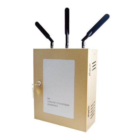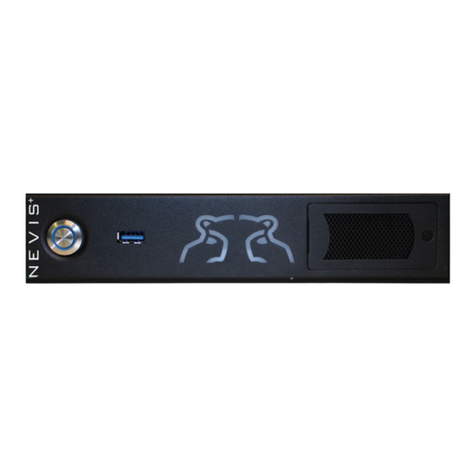
SW5502C
Wireless Serial Server
Figure 4.19 Wireless Status page shows current information of SW550XC............................................................. 32
Figure 4.20 Transition page during the gathering of surrounding wireless network information............................ 33
Figure 4.21 Results of a Site Monitoring of SW550XC Series.................................................................................... 33
Figure 4.22 Network Settings Page (Wireless Client Mode)...................................................................................... 34
Figure 4.23 Network Settings Page for Bridged Interface (AP Client Mode)............................................................. 35
Figure 4.24 Enabling Wireless Profile Option to Add New Access Point................................................................... 36
Figure 4.25 Basic Setting List Webpage after Clicking Add Button ........................................................................... 37
Figure 4.26 Wireless Profile Page ................................................................................................................................ 38
Figure 4.27 Basic Settings for Wireless Connection when Wireless Profile is Enabled ........................................... 39
Figure 4.28 Basic Settings for Wireless Connection when Wireless Profile is Disabled.......................................... 40
Figure 4.29 Results of network scanning when uses “scan network” buttons ......................................................... 42
Figure 4.30 Result when there is no wireless network available in the area............................................................. 42
Figure 4.31 Wireless Advanced Settings Page when Wireless Profile is Disabled and Topology is set to
infrastucture ................................................................................................................................................................... 43
Figure 4.32 Wireless Advanced Settings Page when Wireless Profile is Enabled ................................................... 44
Figure 4.33 COM 1 Port Setting Page ......................................................................................................................... 45
Figure 4.34 Serial Settings Part of COM Port ............................................................................................................. 46
Figure 4.35 Advanced COM Port Settings Page......................................................................................................... 47
Figure 4.36 SNMP/Alert Settings Page ....................................................................................................................... 50
Figure 4.37 E-mail Settings Page ................................................................................................................................ 52
Figure 4.38 Sending Test E-mail Failed ...................................................................................................................... 52
Figure 4.39 System Log Settings Page ....................................................................................................................... 53
Figure 4.40 COM Log Settings Page ........................................................................................................................... 54
Figure 4.41 Event Log Page........................................................................................................................................... 55
Figure 4.42 COM Datalog Page ................................................................................................................................... 56
Figure 4.43 Date/Time Settings Page ......................................................................................................................... 57
Figure 4.44 Admin Settings Page................................................................................................................................ 58
Figure 4.45 Firmware Upgrade Page........................................................................................................................... 59
Figure 4.46 Backup/Restore Setting Page .................................................................................................................. 60
Figure 4.47 Management List Page ............................................................................................................................ 61
Figure 4.48 Successful Ping with No Packet Loss..................................................................................................... 62
Figure 4.49 Unsuccessful Ping with 100% Packet Loss ........................................................................................... 62
Figure 4.50 Reboot Page ............................................................................................................................................. 63
Figure 4.51 Pop-up Windows while Rebooting SW550XC with Reloading Countdown in Seconds........................ 63
Figure 5.1 Link Mode Options for COM 1 Port............................................................................................................ 64
Figure 5.2 An Example of TCP Server Link Mode....................................................................................................... 64
Figure 5.3 Connection Settings for TCP Server Link Mode ....................................................................................... 65
Figure 5.4 TCP Server Link Mode Settings under COM 1 Page................................................................................. 66
Figure 5.5 An Example of TCP Client Link Mode........................................................................................................ 68
Figure 5.6 Connection Settings for TCP Client Link Mode ........................................................................................ 68
Figure 5.7 TCP Client Link Mode Settings under COM 1 Page.................................................................................. 69
Figure 5.8 An Example of UDP Link Mode .................................................................................................................. 70
Figure 5.9 Connection Setting for UDP Link Mode..................................................................................................... 71
Figure 5.10 UDP Link Mode Settings under COM 1 Page.......................................................................................... 71
Figure 5.11 Virtual COM Application in TCP Server Link Mode................................................................................. 73
Figure 5.12 Virtual COM Application in TCP Client Link Mode.................................................................................. 74
Figure 5.13 Pair Connection Master Application in TCP Server Link Mode ............................................................ 75
Figure 5.14 Pair Connection Slave Application in TCP Client Link Mode ................................................................ 76
Figure 5.15 Reverse Telnet Application in TCP Server Link Mode ........................................................................... 77
Figure 5.16 An Example of Network Topology for Multi-Point Pair Connection in UDP Link Mode ...................... 78
Figure 5.17 Setting of Multiple TCP Connection Application via Maximum Connection Option ........................... 79
