3
T 324 - GSM 712 Eng. 04.01.01
We reserve the right to make changes without notice
COSTER
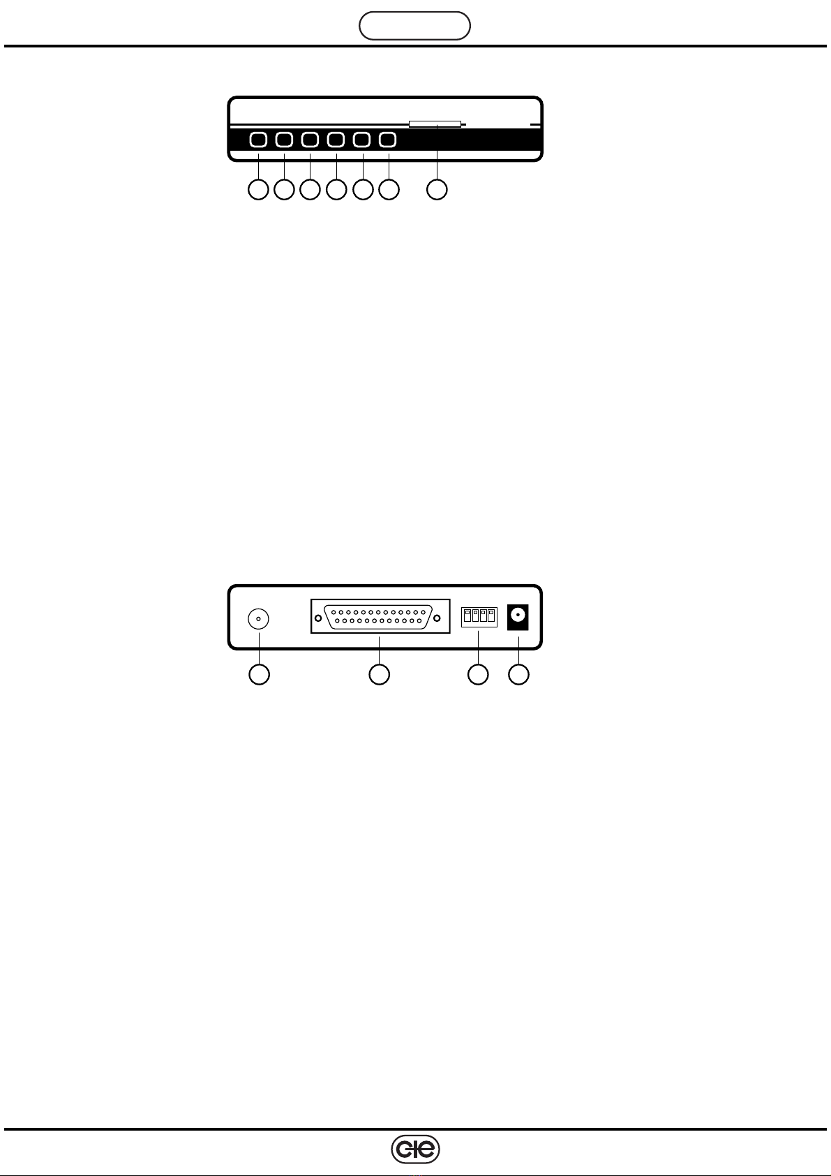
7. CONNECTIONS
– Female connector RS232.
The RS232 female 25-pin D connector (DB25) conforms to recommendation ITU-T V. 24/V.28.
Permits connecting to the telemanagement computer installed in the offices of the telemanager or in those of
supervisory staff.
– Connector for RF antenna.
Theconnectionofthemagneticantenna,suppliedwiththemodem,must becarriedoutbyscrewingupastightly
aspossible the threaded lockingnut, located at theend of the antennacable, on the GSMconnector on the rear
panel.
WARNING: Ensure that the modem is switched off before connecting or disconnecting the antenna.
– Power supply connector
Use the transformer supplied with the modem. Insert the cable connector in the 15V- 50 Hz socket on the rear
panelofthemodem.TheEuropean plugofthetransformeris theninsertedintotheU.K.3-pinadaptor &thelatter
is plugged into the main 3-pin socket.
Eachtimeitisswitchedonthemodemcarriesoutatestlastingabout20secondsattheendofwhichthe“ON”LED
remains lit and the modem is ready to function.
Asanalternative,powerthemodem with a 12VDCsupply;WarningCorrectPolarity Must Be Observed inthis
case the centre pole of the power connector is the positive of the12 V input.
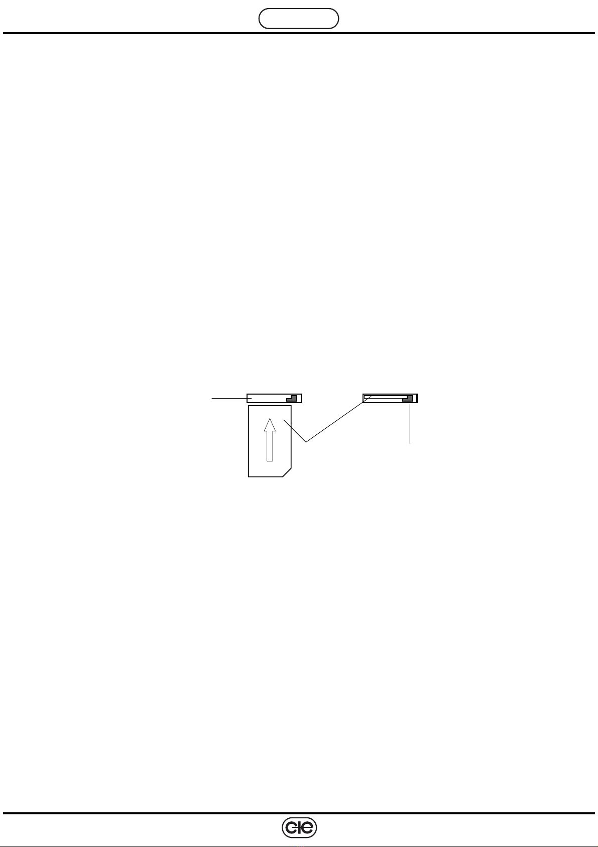
– Connector SIM card.
On the front panel is the slot for inserting the SIM card in the modem.
TheSIMcardmustbeinsertedwiththegoldsidefacingdownwardsandwiththecut-offcornerfacingtowardsthe
right (as in the diagram), pushing it until a light click is felt.
To remove the SIM card depress the red key lightly (see diagram) which will then release the SIM card for
extraction.
WARNING: UNDER NO CIRUMSTANCES MUST THE SIM CARD BE INSERTED OR REMOVED WHILE THE
MODEM IS SWITCHED ON. SUCH OPERATIONS MUST BE CARRIED OUT ONLY WHEN THE MODEM IS
SWITCHED OFF.
8. SIM CARD It is advisable to purchase your SIM card from your chosen GSM network service provider’s agent.
When purchasing it is indispensable to:
– ask for a card enabled for the transmission and reception of data and fax.
Usually, the network operator will supply a SIM card with three telephone numbers:
- a VOICE number to be used for voice TELEPHONE calls.
- a FAX number to be used for fax communications.
- a DATA number to be used for telemanagement.
– ask for the following modes for communication data:
- Asynchronous – “TRANSPARENT” (error correction disabled)
- Asynchronous – “NON TRANSPARENT” (error correction enabled)
Before installing the SIM card in the modem it is essential to disable the PIN code on the card.
This can be done by inserting the SIM CARD in a cellular telephone and altering the security settings of the SIM
using the phone menu system.
Beforefirstusingit,configuretheSWC701telemanagementprogramwiththecommunicationmode(transparentor
non–transparent) as chosen for the card.
SIM card
Insert SIM card
Red key