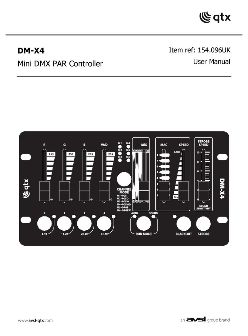
Teknic ClearLink User manual

ClearLink Hardware Manual
Includes wiring information for CCIO-8 (I/O Expansion Board)
Rev. 1.00 / October 29, 2020
U
SER
M
ANUAL

ClearLink Hardware Manual / Rev. 1.00 2
TEKNIC,INC.PHONE (585)784-7454
Table of Contents
Table of Contents.............................................................................................................. 2
Introduction ....................................................................................................................... 4
Welcome................................................................................................................................4
What's in this Document........................................................................................................4
Safety Information............................................................................................................. 5
Precautionary Statement .......................................................................................................5
General Disclaimer ................................................................................................................5
Example ClearLink System ..............................................................................................6
Parts Overview .................................................................................................................. 7
Parts of a ClearLink ...............................................................................................................7
Parts of a CCIO-8 (I/O Expansion Board)..............................................................................8
Powering ClearLink and CCIO-8......................................................................................9
Recommended Power Supply...............................................................................................9
PWR-IO-24VDC.....................................................................................................................9
Wiring DC Power to ClearLink and CCIO-8.........................................................................10
Wiring I/O to ClearLink.................................................................................................... 11
Introduction..........................................................................................................................11
I/O Overview Table..............................................................................................................11
Wiring I/O to the Outer I/O connectors ................................................................................12
I/O-0 through I/O-5 configured as DIGITAL INPUTS...........................................................13
A-9 through A-12 and DI-6 through DI-8 configured as DIGITAL INPUTS...........................14
A-9 through A-12 configured as ANALOG INPUTS.............................................................15
I/O-0 through I/O-5 configured as DIGITAL OUTPUTS.......................................................16
I/O-0 configured as a 4-20mA (or 0-20mA) OUTPUT..........................................................17
ClearLink Combined I/O Header..........................................................................................18
Wiring I/O Devices to CCIO-8..............................................................................................19
I/O-0 through I/O-7 configured as DIGITAL INPUTS...........................................................19
I/O-0 through I/O-7 configured as DIGITAL OUTPUTS.......................................................19
CCIO-8 Combined I/O Header.............................................................................................19
Motor Connectors (M-0, M-1, M-2, M-3) ......................................................................... 20
How to Wire a ClearPath Motor to ClearLink.......................................................................21
ClearPath Controller Cables................................................................................................21

ClearLink Hardware Manual / Rev. 1.00 3
TEKNIC,INC.PHONE (585)784-7454
Wiring a Stepper Motor Drive to ClearLink..........................................................................22
COM-0 (Serial COM Port) ................................................................................................23
COM-0 with 5V compatible RS-232 transceivers ................................................................24
COM-0 configured for 5V logic UART devices ....................................................................25
Appendix A: Specifications ............................................................................................26
ClearLink Specifications.......................................................................................................26
ClearLink I/O Function Table................................................................................................27
CCIO-8 Specifications..........................................................................................................28
CCIO-8 I/O Function Table...................................................................................................29
Appendix B: Mechanical Reference...............................................................................30
ClearLink Mounting and Clearance Dimensions .................................................................30
CCIO-8 Mounting and Clearance Dimensions.....................................................................31
Appendix C: Mating Connectors and Terminals...........................................................32

ClearLink Hardware Manual / Rev. 1.00 4
TEKNIC,INC.PHONE (585)784-7454
Introduction
Welcome
Thank you for purchasing a ClearLink EtherNet/IP Motion and I/O
Controller. This document is a hardware reference manual for the ClearLink
controller, optional I/O expansion board, and optional encoder input board,
PN: CL-ENCDR-DFIN (available soon).
For programming information, please see the ClearLink EtherNet/IP Data
Reference.
What's in this Document
•Parts identification
•Wiring diagrams for common I/O and motor devices
•Power supply requirements
•Mating hardware information
•Product specifications
•Mechanical dimensions
•Mounting information

ClearLink Hardware Manual / Rev. 1.00 5
TEKNIC,INC.PHONE (585)784-7454
Safety Information
Precautionary Statement
Always follow appropriate safety precautions when installing and using any
automated motion control equipment. Motion control systems should be
designed and utilized to prevent personnel from coming into contact with
moving parts and electrical contacts that could potentially cause injury or
death. Read all cautions, warnings, and notes before attempting to install or
operate this device. Follow all applicable codes and standards when using
this equipment. Failure to use this equipment as described may impair or
neutralize protections built into the product.
General Disclaimer
The User is responsible for determining the suitability of this product for his or
her application. The User must ensure that Teknic’s products are installed
and utilized in accordance with all local, state, federal and private governing
bodies and meet all applicable health and safety standards.
Teknic has made all reasonable efforts to accurately present the information
in the published documentation and shall not be responsible for any incorrect
information which may result from unintentional oversights.
Due to continuous product improvements, the product specifications as stated
in the documentation are subject to change at any time and without notice.
The User is responsible for consulting a representative of Teknic for detailed
information and to determine any changes of information in the published
documentation.
Should Teknic’s products be used in an application that is safety critical, the
User must provide appropriate safety testing of the products, adequate safety
devices, guarding, warning notices and machine-specific training to protect
the operator and/or bystanders from injury.

ClearLink Hardware Manual / Rev. 1.00 6
TEKNIC,INC.PHONE (585)784-7454
Example ClearLink System
A-12 A-11 A-10 A-9 D I-8 D I-7 D I-6
M-2 M -3
COMBINED I/O
5V COM-0 5V COM-1
I/O-3 I/O-4 I/O-5I/O-0 I /O-1 I/O-2
M-1M-0
XBee
RESET

ClearLink Hardware Manual / Rev. 1.00 7
TEKNIC,INC.PHONE (585)784-7454
Parts Overview
Parts of a ClearLink
EtherNet/IP
M-2 M-3M-1M-0
ClearLink
A-12 A-11 A-10 A-9 DI-8 DI-7 DI-6
5V COM-0 CCIO Port
COMBINED I/O
I/O-5I/O-4I/O-3I/O-2I/O-0 I/O-1
RESET
Dedicated plug-in
terminal blocks for
each I/O point
Digital Inputs or
0-10V Analog Inputs (4x)
Digital Inputs (3x)
or
Differential Encoder Input (3-channel)
Teknic Encoder Board PN
CL-ENCDR-DFIN *** required.
Card Slot
(not used for ClearLink)
Combined I/O Header
Can be used in only one of the two ways listed
EtherNet/IP Port
USB Port
(not used)
Mounting Holes (2x)
*Digital outputs I/O-0 through I/O-3 have
built-in clamping circuitry and are capable of
driving coils of up to 9-watts max.
I/O-4 , I/O-5 can drive up to 18 watts max.
Reset Switch
Motor Connectors
(4x) M0-M3 Control
ClearPath motors,
step motor drives, or
servo motor drives
Digital Input,
Digital Output*, or
Analog Output
(4-20mA or 0-20mA)
Combined I/O Header
see description below
Communication Port
RJ-45 connector, compatible
with UART, or RS-232 devices
DC Power Input
24VDC
Digital Inputs or
Digital Outputs*
CCIO Port
RJ-45 connector, used to
connect CCIO-8 I/O
expansion module(s)
Breaks out all 13 I/O points.
(Provides an alternative
hookup path to the individual
3-pin I/O connectors.)
Connect optional Teknic Differential
Encoder Board here
(Teknic PN CL-ENCDR-DFIN***).
If Encoder Board is used, DI-6,7,8
3-position connectors cannot be
used and must remain unpopulated.
or
ENCODER BOAR
D
A
VAILABLE
SOO
N.
*
**
ClearLink top and side views

ClearLink Hardware Manual / Rev. 1.00 8
TEKNIC,INC.PHONE (585)784-7454
Parts of a CCIO-8 (I/O Expansion Board)
Combined I/O Header
For alternate hookup of
I/O points (for use with
custom break-out boards,
bulkhead connectors,
harness, etc.)
COM IN (RJ-45)
Serial communication
input from ClearCore
or previous CCIO-8
Mounting Hole
Mounting Hole
Mounting Plate
Aluminum, 2mm
COM OUT (RJ-45)
Serial communication
output to next CCIO-8
if applicable
DC Power Input
24VDC
Digital Inputs or
Digital Outputs (8 total)
Digital Inputs or
Digital Outputs (8 total)
CCIO-8 I/O expansion board

ClearLink Hardware Manual / Rev. 1.00 9
TEKNIC,INC.PHONE (585)784-7454
Powering ClearLink and CCIO-8
ClearLink and CCIO-8 are 24VDC compatible devices. This section includes
ClearLink power supply recommendations and wiring instructions.
Important: Do not use your ClearLink power supply to also supply DC bus
power to servo or stepper drives attached to ClearLink (this applies to
ClearPath motors too!). Always use a separate, dedicated power supply,
such as the IPC-5, that is specifically designed to manage the power and
regenerated energy requirements of servo or step motor drives.
Recommended Power Supply
PWR-IO-24VDC
The PWR-IO-24VDC power supply (Mean Well PN LRS-150-24) is an
inexpensive, 24VDC, 6.5A (156W) switching supply capable of powering most
ClearLink applications. Click here to view product datasheet.
Why choose a "higher current" power supply?
A power supply of 6.5A or more is recommended for ClearLink applications to ensure that
the ClearLink processor always remains powered, even under adverse operating conditions
such as overloads or shorts. Note: Lower current supplies will work with ClearLink, but may
experience shutdowns or brown outs if ClearLink is overloaded or shorted due to use or
application error.

ClearLink Hardware Manual / Rev. 1.00 10
TEKNIC,INC.PHONE (585)784-7454
Wiring DC Power to ClearLink and CCIO-8
See below for instructions on wiring 24VDC power to ClearLink and CCIO-8.
Tools Required
•Slotted screwdriver with max. 2mm wide blade
•Wire cutter/stripper
•3-position screw terminal connector, Molex part # 0395105003
Procedure 1. Turn off power supply.
2. Strip DC output wires from power supply. Expose
approximately 6.5mm (0.25") of bare wire.
3. Fully insert V+ and V- wires fully into terminal block "+" and
ground positions.
4. Tighten terminal screws.
5. Inspect connector for good wire capture. Verify that no wire
insulation is captured in the closure, and that no loose wire
strands are sticking out of the connector.
6. Recommended: Before connecting the terminal block to
ClearLink, test for correct voltage polarity between "+" and
ground terminals.
Strip Length
0.25 in.
6.5 mm
Tighten screws to
approx. 2 in/lbs.
Use 2mm slotted
screwdriver.
ClearCore/ClearLink CCIO-8
PWR
From DC
Power Supply Insert connector(s)
as shown.
Press firmly to seat.
Connecting power to ClearLink and CCIO-8
Chassis Connection
Mount ClearLink and CCIO-8 to a machine frame or chassis continuous with
Protective Earth. Alternately, connect the chassis terminal on the 3-position
power connector to machine frame using conductive hardware.

ClearLink Hardware Manual / Rev. 1.00 11
TEKNIC,INC.PHONE (585)784-7454
Wiring I/O to ClearLink
Introduction
This section discusses the function and wiring of ClearLink and CCIO-8 user-
configurable I/O points.
ClearLink I/O at a Glance
•(13) configurable I/O points
•Up to (13) digital inputs
•Up to (4) analog inputs
•Up to (6) digital outputs (with PWM)
•Up to (1) 4-20mA (or 0-20mA) output
•Separate ground and power for all I/O points (grounds not isolated)
•A dedicated status LED for every I/O point
•Add up to 64 more digital in/out points with Teknic's CCIO-8 (I/O
expansion modules)
I/O Overview Table
The table below lists all ClearLink and CCIO-8 I/O connectors and their
supported I/O types. Refer to the ClearLink programming reference for
instructions on how to configure ClearLink and CCIO-8 I/O connectors.
Label Digital Input Digital
Output
1
0-10V
Analog Input 4-20 mA
Output
2
Servos or
Steppers Encoder Input
IO-0 yes yes yes
IO-1 yes yes
IO-2 yes yes
IO-3 yes yes
IO-4 yes yes
IO-5 yes yes
DI-6 yes yes
5
DI-7 yes yes
5
DI-8 yes yes
5
A-9 yes yes
A-10 yes yes
A-11 yes yes
A-12 yes yes
M-0 yes
3
M-1 yes
3
M-2 yes
3
M-3 yes
3
CCIO-8
4
yes yes
Note 5: Additional encoder board required Teknic PN: CL-ENCDR-DFIN
Note 1: All digital outputs are PWM capable (except for those on the CCIO-8 expansion board).
Note 2: This output can also provide 0-20mA, which is less commonly used.
Note 3: Each motor connector has 3 digital outputs (step, dir., enable) and 1 digital input.
Note 4: There are 8 of these I/O points on the CCIO-8 expansion module.
ClearLink I/O overview table

ClearLink Hardware Manual / Rev. 1.00 12
TEKNIC,INC.PHONE (585)784-7454
Wiring I/O to the Outer I/O connectors
This section explains how to wire common I/O devices to a ClearLink
controller. Each subsection includes a diagram of the ClearLink internal
circuitry and several example hookup diagrams.
EtherNet/IP
M-2 M-3M-1M-0
ClearLink
A-12 A-11 A-10 A-9 DI-8 DI-7 DI-6
5V COM-0 CCIO Port
COMBINED I/O
I/O-5I/O-4I/O-3I/O-2I/O-0 I/O-1
RESET
Digital Inputs or
0-10V Analog Inputs Digital Inputs
Dedicated
indicator LED for
each I/O point
Digital Input, Digital Output,
or 4-20mA (0-20mA) Analog
Output
Digital Inputs or
Digital Outputs
ClearLink I/O connectors

ClearLink Hardware Manual / Rev. 1.00 13
TEKNIC,INC.PHONE (585)784-7454
I/O-0 through I/O-5 configured as DIGITAL INPUTS
Note: The wiring examples shown below also apply to all CCIO-8 I/O points
configured as digital inputs.
Input Equivalent Circuit Typical Sensor Hookup Details
169k
10k
Vsupply (24V)
Vsupply (24V)
3V3
IN[NN]n
Digital “NPN”
Sensor:
Proximity
Optical
Hall-Effect, etc.
G
S
BLK
BLU
BRN
Switch or Relay Contact
G
S
5V/3.3V Logic System
G
S
IMPORTANT:
Inputs are “negative true”:
On<~1.0V, Off>=~1.0V
G
S
“Ease of Use” Note: 5V Sensors
Before using 5VDC sensors, consider either
1) sourcing 24V alternatives, or 2) providing a
separate 5VDC supply to power your 5V
sensors.
*
*Wire colors listed are typical of industrial sensors
Digital “PNP”
Sensor:
Proximity
Optical
Hall-Effect
820 Ω
1 Watt
330 Ω
1/2 Watt
BLK *
BLU
BRN
G
S
Gnd
*Wire colors shown are
typical of industrial sensors
● Resistors sized for 24VDC supply voltage
● External resistors not included

ClearLink Hardware Manual / Rev. 1.00 14
TEKNIC,INC.PHONE (585)784-7454
A-9 through A-12 and DI-6 through DI-8 configured as DIGITAL INPUTS
IMPORTANT:
Inputs are “negative true”:
On<~1.0V, Off>=~1.0V
Input Equivalent Circuit Typical Sensor Hookup Details
Digital “NPN”
Sensor:
Proximity
Optical
Hall-Effect, etc.
G
S
BLK
BLU
BRN
Switch or Relay Contact
G
S
5V/3.3V Logic System
G
S
5k
5V
Vsupply (24V)
20k
3V3
IN[NN]n
G
S
“Ease of Use” Note: 5V Sensors
Before using 5VDC sensors, consider either:
1) sourcing 24V alternatives, or 2) providing a
separate 5VDC supply to power your 5V
sensors.
Digital “PNP”
Sensor:
Proximity
Optical
Hall-Effect
820 Ω
1 Watt
330 Ω
1/2 Watt
BLK *
BLU
BRN
G
S
Gnd
*Wire colors shown are
typical of industrial sensors
● Resistors sized for 24VDC supply voltage
● External resistors not included

ClearLink Hardware Manual / Rev. 1.00 15
TEKNIC,INC.PHONE (585)784-7454
A-9 through A-12 configured as ANALOG INPUTS
ClearLink is compatible with a variety of analog sensors (transducers)
including the following:
•Pressure •Force •Torque
•Temperature •Angle •Inclination
•Distance •Level •Velocity
•Mass •Flow •Electric current
G
S
Out
Gnd
V+
0-10V
Analog
Sensor
G
S
Out
Gnd
V+
4-20mA
Analog
Sensor
499Ω, 1/2 Watt
Note:
Place the 499 Ohm shunt resistor
close to input terminal block.
Loop-
powered
4-20mA
Sensor
V-
V+
G
S
499Ω, 1/2 Watt
Notes:
Place the 499 ohm shunt resistor close to
input terminal block.
Use twisted pair wire as shown to minimize
noise pickup.
G
S
1.4k
CW
1.0k
Engineering Note:
The repeatability of this circuit will be
affected by the drift and regulation of
the power supply connected to
Vsupply. (Values shown for a 24V
supply.)
Potentiometer
Input Equivalent Circuit Typical Sensor Hookup Details
G
S
G
S
G
S
G
S
(Cfg[NN]_AIN_DINn = Hi)
A/D
0-10V
30k Vsupply
(24V)
Ain[NN]
G
S
Typical Sensor Hookup Details
Sensor Notes:
•0-5V output sensors can be used with ClearLink, but there will be a
loss of 1 bit of resolution (provided they are compatible with the
ClearLink supply voltage (Vsupply).
•0-20mA sensors can be used with ClearLink, but there will be some
loss of linearity near zero current (this is sensor dependent).

ClearLink Hardware Manual / Rev. 1.00 16
TEKNIC,INC.PHONE (585)784-7454
I/O-0 through I/O-5 configured as DIGITAL OUTPUTS
Note: The wiring shown in this section also applies to all CCIO-8 points
configured as digital outputs.
Output Equivalent Circuit Typical Actuator Hookup Details
Typical Actuator Hookup Details
Vsupply
(24V)
Vsupply (24V)
*
10k
*
protected FET
0.375A Max.
OUT[NN]
IMPORTANT:
Outputs are “negative true”:
On state turns on transistor, enabling
current in load, pulling output <0.5V
G
S
Coil
Relay
Contactor
Pneumatic Valve
Fluid Valve
Vacuum Valve
Solenoid Guard Lock
Solenoid Actuator
(e.g., diverter)
No Shunt Diode Required
(Outputs have built-in
active clamping)
G
S
M
G
S
DC Motor. Pump, etc.
(single direction)
G
S
G
S
DC Fan
G
S
+
5V/3.3V Logic System
G
S
External clamping diode to logic
supply may be required, consult
logic IC datasheet.
Logic
G
S
G
S
LED Indicator
G
S
G
S
SSR
Input
Output
Solid State Relay
G
S
G
S

ClearLink Hardware Manual / Rev. 1.00 17
TEKNIC,INC.PHONE (585)784-7454
I/O-0 configured as a 4-20mA (or 0-20mA) OUTPUT
ClearLink connector I/O-0 can be configured to supply a variable 4-20mA
analog signal to control a wide variety of analog actuators. A few examples of
devices that can be controlled using 4-20mA signaling include:
•Damper control •Proportional valve
•Pressure regulator •Linear position actuator
•Rotary position actuator •Process meter (display)
•Variable speed display
Output Equivalent Circuit Typical Actuator Hookup Details
Typical Actuator Hookup Details
DAC
Aout00
Vsupply
VoutMAX=
Vsupply-2V
DAC/Vout1
Output produces positive current flow through the
S (signal) pin as shown, i.e., output is “sourcing”
4-20mA
4-20mA RET.
COM
V+ SUPPLY
Notes:
Connect signal and supply return
wires close to output terminal block
Use twisted pair as shown for best
noise immunity
4-wire Actuator
G
S
G
S
3-wire Actuator
G
S4-20mA
COM
V+ SUPPLY
G
S
G
S0-10V
COM
V+ SUPPLY
3-wire 0-10V
Actuator
499/
0.5W
Note:
Place 499 Ohm shunt resistor close
to actuator
G
S
G
S
2-wire Control
EXTERNAL
SUPPLY
May be required
depending on device
4-20mA
COM
G
S
G
S

ClearLink Hardware Manual / Rev. 1.00 18
TEKNIC,INC.PHONE (585)784-7454
ClearLink Combined I/O Header
The ClearLink I/O header (labeled "Combined I/O" on the case) provides an
alternative way to connect I/O devices to ClearLink's I/O points.
Note: This connector can alternately be used to take encoder input from
Teknic PN CL-ENCDR-DFIN encoder board (available soon).
Combined I/O
10x2 Header, 0.10” pitch
A-9
A-11
A-12
DI-6
DI-7
I/O-1
I/O-2
I/O-3
I/O-4+
I/O-5+
A-10
GND
Vsupply
Vsupply
DI-8
I/O-0
Vsupply
GND
I/O-4
I/O-5
Mating Connector (for use with ribbon cable)
Housing: OST/101-206
Ribbon cable: CnC Tech/
304-28-20-MC-0250F
Mating Connector (crimp style)
Housing: AMP/102387-4
Terminals: AMP/87756-4 (22-26AWG)
1
12
34
56
78
910
11 12
13 14
15 16
17 18
19 20
ClearLink I/O Header

ClearLink Hardware Manual / Rev. 1.00 19
TEKNIC,INC.PHONE (585)784-7454
Wiring I/O Devices to CCIO-8
The CCIO-8 board connects to ClearLink's CCIO Port via standard Ethernet
cable (CAT5e or better). CCIO-8 provides 8 additional I/O points per board.
Up to (8) CCIO-8 boards can be connected to a ClearLink.
IMPORTANT NOTES
•All CCIO-8 I/O points are electrically identical to ClearLink I/O points
I/O-1, I/O-2, and I/O-3. The only functional difference is that the
CCIO-8 points cannot output PWM signals.
•CCIO-8 I/O points can be configured as either digital inputs or digital
outputs.
•Do not hook up the accessory encoder input board to CCIO-8
(Encoder board available soon).
I/O-0 through I/O-7 configured as DIGITAL INPUTS
The wiring for all 8 of these I/O points (as inputs) is the same as the wiring for
ClearLink I/O-0 through I/O-5 configured as DIGITAL INPUTS
I/O-0 through I/O-7 configured as DIGITAL OUTPUTS
The wiring for all 8 of these I/O points (as outputs) is the same as the wiring
for ClearLink I/O-0 through I/O-5 configured as DIGITAL OUTPUTS
CCIO-8 Combined I/O Header
The CCIO-8 I/O header (labeled "Combined I/O" on the board) provides an
alternate, functionally identical way to connect I/O devices to ClearLink's I/O
points.
Combined I/O
10x2 Header, 0.10” pitch
CCIO-8 top view
I/O-6
I/O-7
I/O-1
I/O-2
I/O-3
GND
Vsupply
Vsupply
I/O-0
Vsupply
GND
I/O-4
I/O-5
Mating Connector (for use with ribbon cable)
Housing: OST/101-206
Ribbon cable: CnC Tech/
304-28-20-MC-0250F
Mating Connector (crimp style)
Housing: AMP/102387-4
Terminals: AMP/87756-4 (22-26AWG)
Pin 1
12
34
56
78
910
11 12
13 14
15 16
17 18
19 20
CCIO-8 I/O Header

ClearLink Hardware Manual / Rev. 1.00 20
TEKNIC,INC.PHONE (585)784-7454
Motor Connectors (M-0, M-1, M-2, M-3)
ClearLink has four multi-function motor connectors that each have three (3)
specialized outputs and one (1) specialized input. They are plug and play
compatible with Teknic ClearPath motors, but are compatible with many third
party servo/stepper drives.
ClearLink can be programmed to send either of the following types of control
signals to the motor connectors:
•Step & Direction signals to ClearPath-SD series motors or
compatible third-party servo or step motor drives.
OR
•Digital control signals to ClearPath-MC series (Motion Controller)
motors.
IMPORTANT: Only one type of motor control method can be used on any
given ClearLink Controller: either Step and Direction or Digital Control
signals, but not both types on the same ClearLink unit.
ClearLink Motor
Connectors
Et
h
e
rN
et/
I
P
M
-
2
M
-
1
M
-
0
C
l
e
a
r
L
i
n
k
A
-
12
A
-
1
1
A
-
10
A-
9
D
I-
8
DI
-
7
5
V C
O
M-
0
CO
MBINED I/
O
I
/
O
-
5
I
/
O
-
4
I/
O
-
3
I
/
O
-
2
I
/
O
-
0
I
/
O
-
1
RESET
E
ClearLink motor connectors
Note: ClearLink motor connectors are designed to send and receive low-
power signals only.The motor connectors are not designed to directly
power the phase windings of servo or stepper motors.
Table of contents
