www.ismacontrolli.com
The performances stated in this sheet can be modifi ed without any prior notice.
page 1DIM014en | 1st Issue | 07/2022
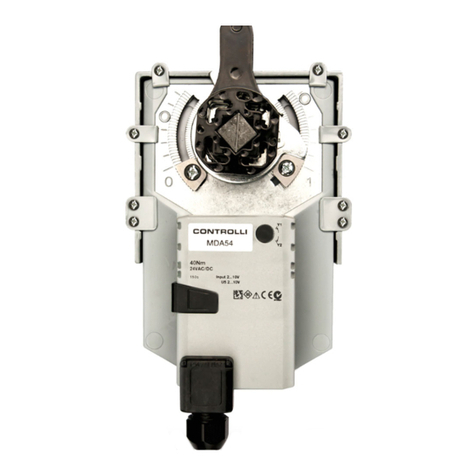
MDLX_B
Damper Actuators
GENERAL
MDLX_B model corresponds to the actuator having 24 V AC power supply without control board. The board assemblymust be
arranged by the user.
Actuator
(without board)
Floating
Board
MDL4x,
MDLPA4*
Prop.
Potentiometric
Board MDL3x
Module**
(Prop. V/I)
MDLS5 (xed
ranges)
iSMA
CONTROLLI
Model
MDLX2B 6 Nm x MDL42 3P
MDLX4B 20 Nm x MDL44 3P
MDLX6B 30 Nm x MDL46 3P
MDLX2B 6 Nm x MDL32 prop. Ohm
MDLX4B 20 Nm x MDL34 prop. Ohm
MDLX6B 30 Nm x MDL36 prop. Ohm
MDLX2B 6 Nm x MDL52 prop V/I
MDLX4B 20 Nm x MDL54 prop V/I
MDLX6B 30 Nm x MDL56 prop V/I
(*) MDLPA4 board = with 1 Kohm feedback potentiometer.
(**) MDLV5 (adjustable elds and ranges) model is available as an alternative to MDLS5. Mother board
MDL4X-MDLPA4-MDL3X BOARDS MOUNTING AND CONNECTIONS
• Remove the actuator cover.
• Mount the mother board paying attention that the centring holes are correctly placed into the rods protruding from the
support and that the 4 support catches t the mother board.
• Connect the stroke end cables to the mother board using the corresponding connectors:
• yellow wire connectors to the G marked connector on the board
• red wire connectors to the R marked connector on the board
• Connect the motor cables by the respective connector (4-wire) to the mother board, as follows:
Control Type Motor Torque
(Nm) Board Type Connector Model (on
Mother Board)
Floating 6MDL4X-MDLPA4 J4 (MDL42)
Floating 20-30 MDL4X-MDLPA4 J1 (MDL44-46)
Prop. 6MDL3X J1 (MDL32-52)
Prop. 20-30 MDL3X J5 (MDL34-36-54-56)
• After linking the connector, insert the cables inside the guide on the board support.
• Mount the gear couple of the potentiometer (present into the packaging), only for MDL3. proportional models.
• For MDLPA4 board see “Accessories and options” installation instructions.
• Mount the plate 8 and the ring 6 on the gear 7.
• Mount simultaneously the gear couple on the potentiometer shaft and on the hexagonal shaft as showed in g. above.
• Make sure that the gear 7 hits on the hexagonal shaft and that it meshes correctly with the gear 3.
