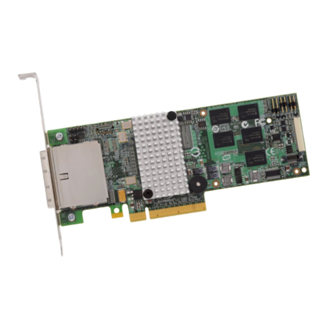
IBM ServeRAID M5025 User manual

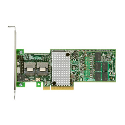
®
ServeRAID M5025
SAS/SATA Controller
USER’S
GUIDE
September 2011

ii
Second Edition (September 2011)
© Copyright International Business Machines Corporation 2011. All rights reserved.
US Government Users Restricted Rights – Use, duplication or disclosure
restricted by GSA ADP Schedule Contract with IBM Corp.

ServeRAID M5025 SAS/SATA Controller User’s Guide iii
Preface
This book is the primary reference and user’s guide for the ServeRAID
M5025 SAS/SATA controller. It contains installation instructions and
specifications for the adapter. In addition, it explains how to install and
use the intelligent Battery Backup Unit (iBBU) that is used with the
ServeRAID-MR controller. In addition, it explains how to install the
ServeRAID M5000 Series Advanced Feature Key on the ServeRAID
M5025 SAS/SATA controller.
For details on how to configure the storage adapter, refer to the
ServeRAID-MR Software User’s Guide. For information about the
operating system drivers, refer to the ServeRAID-MR Device Driver
Installation User’s Guide.
Audience
This document assumes that the reader is familiar with RAID controllers
and related support devices. The people who benefit from this book are:
Engineers who are designing a system that will include the
ServeRAID M5025 SAS/SATA controller
Anyone installing the ServeRAID M5025 SAS/SATA controller in a
RAID system
End users who need to install the iBBU product on the ServeRAID
M5025 SAS/SATA controller
Engineers and managers who are evaluating BBU products for
possible use with ServeRAID-MR controllers
Note: The ServeRAID M5000 Series Battery Assembly is pre-
installed on the ServeRAID M5025 SAS/SATA controller.

iv Preface
End users who need to install a ServeRAID M5000 Series Advanced
Feature Key on a ServeRAID M5025 SAS/SATA controller
Organization
This document has the following chapters and appendices:
Chapter 1, Overview, provides a general overview of the ServeRAID
M5025 SAS/SATA controller.
Chapter 2, ServeRAID M5025 SAS/SATA Controller
Hardware Installation, describes the procedures for installing the
ServeRAID M5025 SAS/SATA controller.
Chapter 3, ServeRAID M5025 SAS/SATA Controller
Characteristics, provides the characteristics and technical
specifications for the ServeRAID M5025 SAS/SATA controller.
Chapter 4, Introduction to the Intelligent Battery Backup Unit,
describes the iBBU model and explains how it operates.
Chapter 5, Installing the Intelligent Battery Backup Unit, explains
how to install the iBBU model.
Chapter 6, Using the Intelligent Battery Backup Unit, explains
how to use and monitor the iBBU model and how to replace it.
Chapter 7, Intelligent Battery Backup Unit Specifications, has
complete technical information and specifications for the iBBU
model.
Chapter 8, Installing a ServeRAID M5000 Series Advanced
Feature Key, describes how to install the ServeRAID M5000 Series
Advanced Feature Key.
Appendix A, Notices, contains information about the warranty,
patents, license inquiries, and trademarks.
Appendix B, Glossary of Terms and Abbreviations, lists and
explains the terms and abbreviations used in this manual.

Preface v
Related Publications
ServeRAID-MR Device Driver Installation User’s Guide
IBM Document Number: 46M1382
This document explains how to install the ServeRAID-MR device driver
for your operating system. The information in this document is
independent of the back-end bus and applies to the ServeRAID-MR
controllers.
ServeRAID-MR Software User’s Guide
IBM Document Number: 46M1381
This document explains how to use the MegaRAID Storage Manager,
WebBIOS, and Command Line Interface (CLI) utilities to configure,
monitor, and maintain the ServeRAID-MR controller and the
storage-related devices connected to them.
IBM Systems Safety Notices
IBM Document Number: G229-9054-01
This book contains safety notices from IBM Systems documentation. The
safety notices include danger and caution notices.
Notices and Statements in This Document
The caution and danger statements in this document are also in the
multilingual IBM Systems Safety Notices document, which is on the
ServeRAID-MR Documentation CD. Each statement is followed by a
reference number that you can use to locate the corresponding
statement in your language in the IBM Systems Safety Notices
document. The following notices and statements are used in this
document:
Note: These notices provide important tips, guidance, or advice.
Important: These notices provide information or advice that might help
you avoid inconvenient or problem situations.

vi Preface
Attention: These notices indicate potential damage to programs,
devices, or data. An attention notice is placed just before
the instruction or situation in which damage might occur.
CAUTION: These statements indicate situations that can be potentially
hazardous to you. A caution statement is placed just before
the description of a potentially hazardous procedure step or
situation.
DANGER:These statements indicate situations that can be poten-
tially lethal or extremely hazardous to you. A danger
statement is placed just before the description of a
potentially lethal or extremely hazardous procedure
step or situation.
Revision History
IBM Customer Support
Web site:
http://www.ibm.com/support/us/en/
Safety Instructions
Use the following safety guidelines to help protect your computer system
from potential damage and to ensure your own personal safety.
Note: Use the ServeRAID M5025 SAS/SATA controller
with UL-listed Information Technology Equipment (ITE)
products only.
Edition/Date Remarks
Second Edition
September 2011
Updated Chapter 6.
First Edition
August 2010
Initial release of document.

Preface vii
DANGER
When working on or around the system, observe the following precautions:
Electrical voltage and current from power, telephone, and communication
cables are hazardous. To avoid a shock hazard:
Connect power to this unit only with the provided power cord. Do not use
the provided power cord for any other product.
Do not open or service any power supply assembly.
Do not connect or disconnect any cables or perform installation,
maintenance, or reconfiguration of this product during an electrical storm.
The product might be equipped with multiple power cords. To remove all
hazardous voltages, disconnect all power cords.
Connect all power cords to a properly wired and grounded electrical
outlet. Ensure that the outlet supplies proper voltage and phase rotation
according to the system rating plate.
Connect any equipment that will be attached to this product to properly
wired outlets.
When possible, use one hand only to connect or disconnect signal cables.
Never turn on any equipment when there is evidence of fire, water, or
structural damage.
Disconnect the attached power cords, telecommunications systems,
networks, and modems before you open the device covers, unless
instructed otherwise in the installation and configuration procedures.
Connect and disconnect cables as described in the following procedures
when installing, moving, or opening covers on this product or attached
devices.
To disconnect:
1. Turn off everything (unless instructed otherwise).
2. Remove the power cords from the outlets.
3. Remove the signal cables from the connectors.
4. Remove all cables from the devices.
To connect:
1. Turn off everything (unless instructed otherwise).
2. Attach all cables to the devices.
3. Attach the signal cables to the connectors.
4. Attach the power cords to the outlets.
5. Turn on the devices.
(D005)

viii Preface
CAUTION:
The battery is a lithium ion battery and can present a fire or chemical burn
hazard if mistreated. Do not dissassemble, heat above 100 C (212 F), or
incinerate. To avoid possible explosion, do not burn. Keep away from
children. Exchange only with the IBM-approved part. Recycle or discard the
battery as instructed by local regulations. In the United States, IBM has a
process for the collection of this battery. For information, call 1-800-426-
4333. Have the IBM part number for the battery unit available when you call.
(C007)
Protecting against Electrostatic Discharge – Static electricity can
harm delicate components inside your computer. To prevent static
damage, discharge static electricity from your body before you touch any
of your computer’s electronic components, such as the microprocessor.
You can do so by touching an unpainted metal surface, such as the
metal around the card-slot openings at the back of the computer.
As you continue to work inside the computer, periodically touch an
unpainted metal surface to remove any static charge your body may
have accumulated. In addition to the preceding precautions, you can also
take the following steps to prevent damage from electrostatic discharge:
When unpacking a static-sensitive component from its shipping
carton, do not remove the component from the antistatic packing
material until you are ready to install the component in your
computer. Just before unwrapping the antistatic packaging, be sure
to discharge static electricity from your body.
When transporting a sensitive component, first place it in an
antistatic container or packaging.
Handle all sensitive components in a static-safe area. If possible, use
antistatic floor pads and workbench pads.

ServeRAID M5025 SAS/SATA Controller User’s Guide ix
Contents
Chapter 1
Overview
1.1 Overview 1-1
1.2 ServeRAID M5025 SAS/SATA Controller Description and
Limitations 1-3
1.2.1 Controller Limitations 1-3
1.3 General Description 1-4
1.4 Configuration Scenarios 1-5
1.4.1 Number of Physical Disks Supported 1-7
1.5 Benefits of the SAS Interface 1-7
1.5.1 PCI Express Architecture 1-8
1.5.2 Operating System Support 1-8
1.6 Summary of the ServeRAID M5025 SAS/SATA Controller
Characteristics 1-9
1.6.1 SAS Features 1-10
1.6.2 SAS Array Limitations 1-10
1.6.3 SATA II Features 1-11
1.6.4 PCI Express Performance 1-12
1.6.5 Usability Features 1-12
1.6.6 Flexibility Features 1-12
1.6.7 Drive Roaming 1-13
1.6.8 Drive Migration 1-14
1.7 Hardware Specifications 1-15
1.8 Technical Support 1-16
Chapter 2
ServeRAID M5025 SAS/SATA Controller Hardware Installation
2.1 Requirements 2-1
2.2 Quick Installation 2-2

xContents
2.3 Detailed Installation 2-2
2.4 After Installing the Controller 2-6
2.5 Connecting the ServeRAID M5025 Controller to a Drive Enclosure
2-6
2.6 Replacing a Failed Controller Containing Data in the iBBU 2-7
Chapter 3
ServeRAID M5025 SAS/SATA Controller Characteristics
3.1 ServeRAID M5025 SAS/SATA Controller 3-1
3.1.1 Board Layout and Connector Information 3-1
3.2 ServeRAID M5025 SAS/SATA Controller Characteristics 3-3
3.3 Technical Specifications 3-3
3.3.1 Controller Specifications 3-4
3.3.2 Array Performance Features 3-5
3.3.3 Fault Tolerance 3-5
3.3.4 Power Supply Requirements for the ServeRAID M5025
SAS/SATA Controller 3-6
3.3.5 Operating and Non-operating Conditions 3-7
3.3.6 Safety Characteristics 3-7
Chapter 4
Introduction to the Intelligent Battery Backup Unit
Chapter 5
Installing the Intelligent Battery Backup Unit
5.1 Installing the iBBU on the ServeRAID M5025 Controller 5-2
5.1.1 Connecting the iBBU Remotely to the ServeRAID M5025
SAS/SATA Controller 5-5
Chapter 6
Using the Intelligent Battery Backup Unit
6.1 Monitoring the IBBU with the MegaRAID Configuration Utilities
6-2
6.1.1 Monitoring the iBBU with the WebBIOS Configuration
Utility 6-2
Setting the Learn Delay Interval 6-5
Setting the Learn Mode 6-6

Contents xi
6.1.2 Monitoring the iBBU with the MegaCLI Utility 6-6
Display BBU Information 6-6
Display BBU Status Information 6-7
Display BBU Capacity 6-8
Display BBU Design Parameters 6-9
Display Current BBU Properties 6-9
Start BBU Learning Cycle 6-10
Place Battery in Low-Power Storage Mode 6-10
Set BBU Properties 6-10
6.1.3 Monitoring the iBBU with the MegaRAID Storage
Manager 6-11
Battery Learn Cycle 6-11
Setting the Learn Cycle Properties 6-12
Starting a Learn Cycle Manually 6-12
6.2 Replacing the Battery Backup Unit 6-13
6.3 Resolving a Configuration Mismatch 6-13
Chapter 7
Intelligent Battery Backup Unit Specifications
7.1 Intelligent Battery Backup Unit Specifications 7-1
7.2 Battery Life and Data Retention Time 7-2
Chapter 8
Installing a ServeRAID M5000 Series Advanced Feature Key
8.1 Installing the ServeRAID M5000 Series Advanced Feature Key on
the ServeRAID M5025 SAS/SATA Controller 8-1
Appendix A Notices
A.1 Trademarks A-2
A.2 Important Notes A-3
Appendix B
Glossary of Terms
and Abbreviations

xii Contents

Contents xiii
Figures
1.1 Example of a SAS Direct-Connect Application 1-6
1.2 Example of a SAS RAID Controller Configured with an
LSISASx12 Expander 1-6
2.1 ServeRAID M5025 Controller Installation in a PCI Express Slot
2-4
2.2 Connecting the ServeRAID M5025 Controller to a Drive
Enclosure 2-7
3.1 Card Layout for the ServeRAID M5025 RAID Controller 3-2
5.1 Intelligent Battery Backup Unit 5-2
5.2 Installing the iBBU Daughtercard on the ServeRAID M5025
SAS/SATA Controller 5-4
5.3 Installing the ServeRAID M5025 SAS/SATA Controller 5-5
5.4 Connecting the iBBU Remotely to the ServeRAID M5025
SAS/SATA Controller 5-6
6.1 First Controller Properties Screen 6-3
6.2 Second Controller Properties Screen 6-4
6.3 Battery Module Screen 6-5
8.1 M5000 Series Advanced Feature Key 8-1
8.2 Installing the ServeRAID M5000 Series Advanced Feature Key
on the M5025 ServeRAID SAS/SATA Controller 8-2

xiv Contents

Contents xv
Tables
1.1 Physical Devices Required for Each RAID Level 1-7
1.2 ServeRAID M5025 SAS/SATA Controller Array Limitations 1-10
1.3 ServeRAID M5025 SAS/SATA Controller
Specifications 1-15
3.1 ServeRAID M5025 SAS/SATA Controller – Connectors 3-2
3.2 ServeRAID M5025 SAS/SATA Controller Characteristics 3-3
3.3 ServeRAID M5025 SAS/SATA Controller Specifications 3-4
3.4 Array Performance Features 3-5
3.5 Fault Tolerance Features 3-6
3.6 Power Supply for the ServeRAID M5025 Controller 3-7
6.1 Display BBU Information 6-7
6.2 Display BBU Status Information 6-7
6.3 Display BBU Capacity Information 6-8
6.4 Display BBU Design Parameters 6-9
6.5 Display Current BBU Properties 6-9
6.6 Start BBU Learning Cycle 6-10
6.7 Place Battery in Low-Power Storage Mode 6-10
6.8 Set BBU Properties 6-10
7.1 Intelligent Battery Backup Unit Specifications 7-1
7.2 Reference Data Retention Times 7-2

xvi Contents

ServeRAID M5025 SAS/SATA Controller User’s Guide 1-1
Chapter 1
Overview
This section provides a general overview of the ServeRAID®M5025
SAS/SATA controller with RAID control capabilities. It consists of the
following sections:
Section 1.1, “Overview”
Section 1.2, “ServeRAID M5025 SAS/SATA Controller Description
and Limitations”
Section 1.3, “General Description”
Section 1.4, “Configuration Scenarios”
Section 1.5, “Benefits of the SAS Interface”
Section 1.6, “Summary of the ServeRAID M5025 SAS/SATA
Controller Characteristics”
Section 1.7, “Hardware Specifications”
Section 1.8, “Technical Support”
1.1 Overview
The ServeRAID M5025 Serial Attached SCSI (SAS)/Serial ATA II (SATA
II) controller is a high-performance intelligent PCI Express-to-SAS/SATA
II adapter with RAID control capabilities. The ServeRAID M5025
controller provides reliability, high performance, and fault-tolerant disk
subsystem management. It is an ideal RAID solution for the external
storage of workgroup, departmental, and enterprise systems. The
controller offers a cost-effective way to implement RAID in a server.
SAS technology brings a wealth of options and flexibility with the use of
SAS devices and SATA II devices within the same storage infrastructure.
However, SAS devices and SATA devices bring individual characteristics
that make each one a more suitable choice depending on your storage

1-2 Overview
needs. MegaRAID®gives you the flexibility to combine these two similar
technologies on the same controller and within the same enclosure.
Note: You cannot mix SAS drives and SATA drives within the
same virtual disk(s).
The ServeRAID M5025 controller is based on the MegaRAID
first-to-market SAS IC technology and proven technology. As the
second-generation PCI Express controller, the ServeRAID M5025
controller addresses the growing demand for increased data throughput
and scalability requirements across midrange and enterprise-class server
platforms. IBM offers a family of SAS controllers to address the needs
for both internal solutions and external solutions.
The innovative intelligent Battery Backup Unit (iBBU) can be used with
the ServeRAID M5025 controller.The iBBU provides protection of cached
data, which allows system builders to protect cached data even during
the most catastrophic system failures. You can install the iBBU directly
on the controller or mount it remotely in the chassis and connect it to the
controller with a cable.
Note: You must charge the battery before use. See Chapter 4,
“Introduction to the Intelligent Battery Backup Unit,” for
more information about the intelligent battery backup unit.
The ServeRAID M5000 Series Advanced Feature Key enables support
for RAID 6 configurations and self-encrypting disks (SED) on the
ServeRAID M5025 SAS/SATA controller. The ServeRAID M5000 Series
Advanced Feature Key mounts directly on the controller. See Chapter 8,
“Installing a ServeRAID M5000 Series Advanced Feature Key” for
installation instructions.
The controller supports the SAS protocol as described in the Serial
Attached SCSI Standard, version 1.1. It also supports the Serial ATA II
(SATA II) protocol defined by the Serial ATA Specification, Version 1.0a,
and the Serial ATA II; Extension to the Serial ATA Specification, Version
1.1. SATA II is an extension to SATA 1.0a. The ServeRAID M5025
controller is a versatile controller that provides the backbone of both
server and high-end workstation environments.
Each port on the ServeRAID M5025 controller supports SAS devices
and/or SATA II devices using the following:

ServeRAID M5025 SAS/SATA Controller Description and Limitations 1-3
SAS Serial SCSI Protocol (SSP), which enables communication with
other SAS devices
SATA II, which enables communication with other SATA II devices
Serial Management Protocol (SMP), which communicates topology
management information directly with an attached SAS expander
device
Serial Tunneling Protocol (STP), which enables communication with
a SATA II device through an attached expander
1.2 ServeRAID M5025 SAS/SATA Controller Description and
Limitations
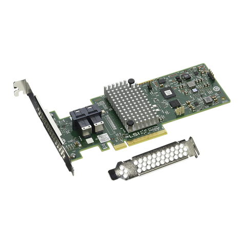
The ServeRAID M5025 controller is available with eight PHYs. The
controller has one LSISAS2108 ROC (RAID-on-chip) processor that
controls eight external SAS/SATA ports through two x4 SAS external
connectors.
1.2.1 Controller Limitations
The ServeRAID M5025 controller has the following limitations:
You can connect only one device per SAS PHY unless you use an
expander
You can use a maximum cable length of 10 feet (using shorter
cables is preferred)
Cables have to meet the SAS specification
You cannot mix SAS drives and SATA drives in the same virtual disk
You cannot mix SAS or SATA Solid State Drives (SSDs) and legacy
mechanical drives (SAS or SATA) in the same virtual disk
You cannot mix Solid State Drives and Solid State SATA Drives in
the same virtual disk
See Section 3.3.4, “Power Supply Requirements for the ServeRAID
M5025 SAS/SATA Controller,” for information about the power
requirements, and Section 3.3.5, “Operating and Non-operating
Conditions” for information about the minimum and the maximum
temperature ranges

1-4 Overview
1.3 General Description
The ServeRAID M5025 controller brings 6.0 Gbit/s Serial Attached SCSI
(SAS) and 3.0 Gbit/s Serial ATA II (SATA II) performance to host
adapter, workstation, and server designs. The controller supports
external storage devices, which allows you to use a system that supports
enterprise-class SAS drives, and desktop-class SATA II drives. Each
ServeRAID M5025 controller can connect to drives directly. Simplified
cabling between devices is an additional benefit.
This controller is based on the LSISAS2108 ROC device. This device is
compliant with the Fusion-MPT architecture and provides a PCI Express
x8 interface.
The controller integrates eight high-performance SAS/SATA II PHYs and
a PCI Express bus master DMA core. Each of the eight PHYs is capable
of 6.0 Gbit/s SAS link rates and 3.0 Gbit/s SATA II link rates.
The LSISAS2108 ROC device provides an eight-lane, 5-Gbit/s PCI
Express host interface, eight 6.0 Gbit/s SAS ports or 3.0 Gbit/s SATA
ports, and a full-featured, hardware-based RAID implementation. The
LSISAS2108 ROC device integrates a high-speed DDR/DDR2 SDRAM
interface with a hardware RAID assist engine for parity calculations. The
LSISAS2108 ROC device provides the maximum benefits of a RAID
system and enables you to configure the system to satisfy your system
requirements.
The LSISAS2108 ROC device increases system performance and
provides fault-tolerant data storage. The LSISAS2108 supports data
striping across multiple disks, which reduces disk access time because
multiple disks simultaneously read or write data. The LSISAS2108 ROC
device backs up data with either data mirroring or a parity block. Either
backup method enables you to recover lost data in the event of a disk
failure. You can select the data backup method that best suits your
needs. A hardware RAID assist exclusive-OR (XOR) engine speeds
parity generation and checking and reduces system-access times.
The controller supports the SAS protocol as described in the Serial
Attached SCSI Standard, version 1.1. In addition, it supports the Serial
ATA II (SATA II) protocol defined by the Serial ATA Specification,
Version 1.0a, and the Serial ATA II; Extension to the Serial ATA
Other manuals for ServeRAID M5025
1
Table of contents
Other IBM Controllers manuals

IBM
IBM 3745 130 Setup guide

IBM
IBM Nways 3746-900 Service manual

IBM
IBM ServeRAID-MR10is User manual

IBM
IBM 3745 Series Quick setup guide

IBM
IBM 3174 Reference manual

IBM
IBM 3720 User manual

IBM
IBM CPC700 User manual

IBM
IBM 3708 Service manual

IBM
IBM 3720 Quick setup guide

IBM
IBM Netfinity ServeRAID-3H User manual
IBM
IBM N6000 Series Manual

IBM
IBM 3745 Series Setup guide

IBM
IBM FlashSystem 900 User manual

IBM
IBM SAS RAID Series User manual

IBM
IBM 3745 Series Parts list manual

IBM
IBM SAN Volume Controller 2145-CG8 Manual

IBM
IBM ServeRAID M1215 SAS User manual

IBM
IBM ServeRAID-4 Ultra160 Series User manual

IBM
IBM 3746-900 Instruction Manual

IBM
IBM 1L Setup guide