Teknion interpret WWSSC Operating and maintenance instructions

Single - Sided Complete Frame (WWSSC),
Wire Gap Worksurface (WWWRW)
Part and Product Identification
Section:
Description: Page No:
Date:
Rev. No: 4
COMPLETE FRAME AND WIRE GAP WORKSURFACE - SINGLE SIDED
FRAMES, SUPPORTS AND WORKSURFACES
Aug 2017 1 of 12
INT_009
interpret
Installation Guides
A
G
F
H
Angled Leg Frame shown
I
J
C1
E
M
Wire Gap Worksurface
(WWWRW) x1
O
A-End Leg, Angle
Single Sided
(N02-3700) x1
Left & 1 Right
D-1/4-20x3-1/2 Flat Head
Machine Quad
(E01-0771) x2
E-Front Standoff
(B02-0658) xqty varies
F-Return Center Rail
Assembly
(N02-2150) x1
H-Modesty, Single Sided
(C05-7238) x1
O-Gable Corner Bracket
L/R
(X05-0273) x2
I-Infill Bottom Bracket
(A16-0947) x2
K-1/4-20 UNC x0.500"
2A, Cross Square
Socket, Truss Head,
Machine Steel, Zinc
(E01-0110) x8
or x12
N-#10x0.875 Quad Pan
Washer
(E07-0077) x 6
or x12
L-#8118x1/2 Cross
Square Comb, Self
(E07-0012) x2
M-Worksurface Support
Bracket
(N09-4134) x2
or x4
B-End Leg, Straight
Single Sided
(N02-3698) x1
Left & 1 Right
G-Return Center Rail Cap
(N02-2151) x2
J-Infill Bottom Bracket
Cover
(A25-0389) x2
Q-5/16-18 x 3/8 Hex Nut
1/2A/F .190 Thick
(E03-0551) x6
or x8
P-5/16-18x3/8 Button
Head, Hex Socket
(E01-0798) x6
or x10
R-Interpret Drilling
Template
(A16-1623) x1
OR
C2-5/16-18x2.5 Socket Head
Cap Screw
(E01-0756) x8
C3-5/16-18 Hex Nut 1/2 A/F
.265 Thick
(E01-0755) x8
C1-Transverse Beam
Assembly
(N02-3688) x1
Leveler Cover is
located inside Leg,
assembled and
secured in place
with tape.

Section:
Description: Page No:
Date:
REMOVE NUTS AND SCREWS
Aug 2017 2 of 12
INT_009
COMPLETE FRAME AND WIRE GAP WORKSURFACE - SINGLE SIDED
FRAMES, SUPPORTS AND WORKSURFACES
interpret
Installation Guides
STEP 1: Remove Screw and Nut from Clamp as shown on illustration.STEP 1: Remove Screw and Nut from Clamp as shown on illustration.
Do Not Remove
C2
C3
C1
C3
C2
C1
End Gable Connection
Mid Gable Connection

Section:
Description: Page No:
Date:
RELOCATE CLAMP
Aug 2017 3 of 12
INT_009
COMPLETE FRAME AND WIRE GAP WORKSURFACE - SINGLE SIDED
FRAMES, SUPPORTS AND WORKSURFACES
interpret
Installation Guides
STEP 2: Remove Clamp.
Clamps at End Gable Location
Clamps at Mid Gable Location
Clamp to be removed and repositioned to
End Gable Postion
Clamps at End Gable Location
Refer to highlighted holes to
fasten Clamps for End Gable
Position.
C3
C2

Section:
Description: Page No:
Date:
CONNECT END GABLES AND TRANSVERSE BEAM SECURE WITH FASTENERS
INT_009
4 of 12
Aug 2017
COMPLETE FRAME AND WIRE GAP WORKSURFACE - SINGLE SIDED
FRAMES, SUPPORTS AND WORKSURFACES
interpret
Installation Guides
STEP 4 : Fasten together using Socket Cap Screw and Nuts. Level and square the whole
assembly.
STEP 3: Bring End Gables and Central Transverse Beam Assembly together. Line up the
middle set of holes on the End Gable Cross Beams with Clamp Brackets holes.
Position End Gables
with holes facing inward.
C2
C3
A1
End Gable Connection

Section:
Description: Page No:
Date:
REMOVE SCREWS FROM THE GABLE FASTEN GABLE CORNER BRACKETS
INT_009
5 of 12
Aug 2017
COMPLETE FRAME AND WIRE GAP WORKSURFACE - SINGLE SIDED
FRAMES, SUPPORTS AND WORKSURFACES
interpret
Installation Guides
STEP 6: Using the same screws install two Gable Corner Brackets.STEP 5: Remove two screws from both gables as shown.
M

Section:
Description: Page No:
Date:
RAIL ASSEMBLY SLIDING NUTS INTO POSITION
INT_009
6 of 12
Aug 2017
COMPLETE FRAME AND WIRE GAP WORKSURFACE - SINGLE SIDED
FRAMES, SUPPORTS AND WORKSURFACES
interpret
Installation Guides
STEP 8: Slide Nuts inside the channel to line them up with holes in both Gable Corner
Brackets. Place remaining Nuts in approximate position for future installation.
STEP 7: Insert Hex Nuts into Rail underside channel. There should be one Nut for each Gable
Corner Bracket and two for each Worksurface Support Bracket.. Install Rail Cap both sides of
the Rail. Rotate set screws to secure Caps in place.
G
F
Q
O
Q

Section:
Description: Page No:
Date:
INSTALL RAIL ASSEMBLY TO THE FRAME ATTACH MODESTY
INT_009
7 of 12
Aug 2017
COMPLETE FRAME AND WIRE GAP WORKSURFACE - SINGLE SIDED
FRAMES, SUPPORTS AND WORKSURFACES
interpret
Installation Guides
STEP 10: Fasten Modesty Panel to Corner Brackets. Make it loose connection.STEP 9: Line up the Rail with Nuts and holes in the Gable Corner Brackets align. Fasten with
Screws. Don't tighten.
P
FH
Underside View
K
Do not tighten!

Section:
Description: Page No:
Date:
PREPARATION FOR ATTACH MODESTY TO LEG ATTACH INFILL BOTTOM BRACKET TO MODESTY
INT_009
8 of 12
Aug 2017
COMPLETE FRAME AND WIRE GAP WORKSURFACE - SINGLE SIDED
FRAMES, SUPPORTS AND WORKSURFACES
interpret
Installation Guides
STEP 12: Fasten Infill Bottom Brackets to the Modesty. Use pilot holes for location.STEP 11: Align Drilling Template with the bottom of Modesty and push it against the Leg.
Mark the location to be drill as shown. Push Modesty out of the way and drill the marked
location.
NOTE: Please mark another pilot hole if End Gable is specified.
Underside VIew
K
I
ALIGN
NOTE: Make sure to position
Drilling Template as shown.
Please mark another pilot hole if
End Gable is specified.
Modesty End Gable
(Optional)
R

Section:
Description: Page No:
Date:
FASTEN MODESTY TO LEGS SUPPORT BRACKET ALIGNEMENT
INT_009
9 of 12
Aug 2017
COMPLETE FRAME AND WIRE GAP WORKSURFACE - SINGLE SIDED
FRAMES, SUPPORTS AND WORKSURFACES
interpret
Installation Guides
STEP 14: Line up each Worksurface Support Bracket with sets of inserts on the Modesty. Push
the top of Modesty for easier access to the Rail channel. Adjust Nuts inside channel to align
with Bracket holes.
C
L
J
M
Push the top of
the Modesty for
an easieraccess
L
Q
STEP 13: Fasten Infill Bottom Brackets to back legs using predrilled holes. Slide Bracket Cover
on the top of them.

Section:
Description: Page No:
Date:
FRAMES, SUPPORTS AND WORKSURFACES FRAMES, SUPPORTS AND WORKSURFACES
INT_009
10 of 12
Aug 2017
COMPLETE FRAME AND WIRE GAP WORKSURFACE - SINGLE SIDED
FRAMES, SUPPORTS AND WORKSURFACES
interpret
Installation Guides
STEP 15. After Bracket is placed in the space between Rail and Modest, with holes aligned with
Nuts, secure it with Screws provided. Continue with remaining Brackets. Tighten Corner
Bracket to Rail screws.
P
Underside View
K
STEP 16: Move Modesty back to it's original location. Fasten Brackets to the Modesty.
Move Modesty back
to original location
Tighten Screws!

Section:
Description: Page No:
Date:
LEVEL INSTALL LEVELER COVERS AND SPACER
INT_009
11 of 12
Aug 2017
COMPLETE FRAME AND WIRE GAP WORKSURFACE - SINGLE SIDED
FRAMES, SUPPORTS AND WORKSURFACES
interpret
Installation Guides
STEP 18: Lock each leveler and remove tape so Leveler Cover can slide down.STEP 17: Level and square. Tighten screws and bolts.
E
Tighten

Section:
Description: Page No:
Date:
LOWER WORKSURFACE ON THE FRAME FASTEN
INT_009
12 of 12
Aug 2017
COMPLETE FRAME AND WIRE GAP WORKSURFACE - SINGLE SIDED
FRAMES, SUPPORTS AND WORKSURFACES
interpret
Installation Guides
STEP 20: Fasten with screws provided. Inside set of inserts are to be used for Complete Frame.
The second set is for Mid Gable connection.
STEP 19: Line up holes in Clamp Brackets and inserts underneath of Worksurface. Place
Worksurface on the top of the frame.
Underside View
Top View
D
N
This manual suits for next models
1
Popular Tools Storage manuals by other brands
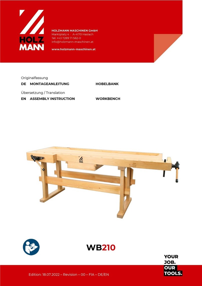
Holzmann
Holzmann WB210 Assembly instruction

Husky
Husky H27CH5TR4BGK Use and care guide
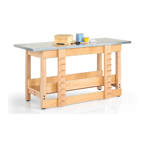
DIVERSIFIED WOODCRAFTS
DIVERSIFIED WOODCRAFTS SHAIN GSB-6024 Assembly instruction
Grizzly
Grizzly H7725 instructions
Husky
Husky HOTC4412BN1S Use and care guide

Seville Classics
Seville Classics UltraDurable SHE15390B manual


