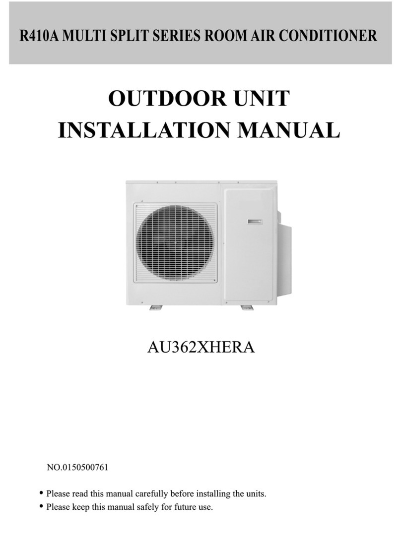
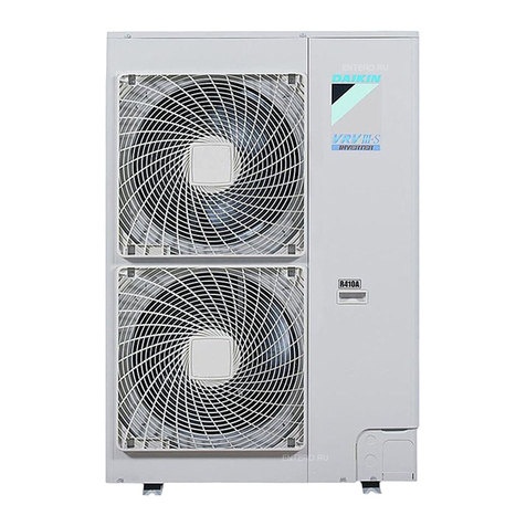
Tekno Point MDV D Series User manual

MDV[D]Series
DigitalScrollCentralAirConditionerOutdoorUnit
INSTALLATIONMANUAL
Pleasereadthismanualcarefullybeforeinstallationandkeep
thismanualforfuturereference.
8 HP = 25.2 kW
10 HP = 28 kW
12 HP = 33.5 kW
14 HP = 40 kW
16 HP = 45 kW

INSTALLATIONLOCATION
Outdoorunitinstallationmanual
Outline
Name
1
1
Function
Qty.
90
elbow
Holesiteforforklift
Chassis
1
1
1
1
1
2
PRECAUTIONS
1.Thisinstallationmanualisfortheoutdoorunit.
2.Refertotheindoorunitinstallationmanualforindoorparts
installation.
3.Pleasereadthepowersourceunitinstallationmanualto
installthepowersourceunit.
4.Pleaserefertotherefrigerantdistributorinstallation
manualtoinstalltherefrigerantdistributor.
KEYPOINTSININSTALLATION
INSTALLATION
Confirmthemodelandnameofyourairconditioner
toavoidinstallationmistakes.
REFRIGERANTPIPING
Separatelypurchasedrefrigerantdistributor(branch
joint,branchheaderpipe)shouldbeusedintheprocess
ofrefrigerantpiping.
Chargenitrogenundercertainpressureintherefrigerant
pipingbeforewelding.
Heatinsulationshouldbedonetorefrigerantpiping.
Aftertheinstallingrefrigerantpiping,donotelectrifythe
indoorunitbeforetheairtighttestandvacuum.
Refrigerantpipingshouldaccordwithspecified
diameter.
AIRTIGHTTEST
Refrigerantpipingmustbetestedforgasproof
[3.8MPa(40kgf/cm)nitrogen.]
2
VACUUM
Vacuumpumpmustbeused,andvacuumingshould
bedonefromthegassideandliquidside
simultaneously.
ADDREFRIGERANT
Whentheactualpipeislongerthanthefiduciallength,
theaddedrefrigerantvolumeofeveryoutdoorunit
dependsonthecalculatingaccordingtotheactuallength.
Filltheformontheoutdoorunitelectriccontrolboxwith
theaddedvolume,lengthofpipes(actuallength)andthe
relativeheightdropbetweenoutdoorunitandindoorunit.
WIRING
Choosepowercapacityandwirediameteraccordingto
thedesignmanual.Thepowercordoftheairconditioner
shouldbewiderthanthepowercordofordinarymotor.
Connecttheindoorunittothepowerafterairtighttest
andvacuuming.
Donottwistorcrossthepowercord(380V3N~)with
wiring(lowvoltage)betweenindoorandoutdoorunit,or
mishandlingmayoccur.
Settheaddressofoutdoorunit,seeAddressdial
ofoutdoorunit “
”
TESTRUNNING
Thetestrunningcannotbeginuntiltheoutdoorunithas
beenconnectedtothepowerfor12hr.
Removesixspongesatthebackofunit.Pleasehandle
withcaretoavoiddamagetofin,whichwilldecrease
heatexchangingefficiency.
1.Pleasekeepawayfromthefollowingplace,or
malfunctionofthemachinemaybecaused:
2.Theinsulationofthemetalpartsofthebuildingandthe
airconditionershouldcomplywiththeregulationof
NationalElectricStandard.
CAUTION
Thereiscombustiblegasleakage.
Thereismuchoil(includingengineoil)ingredient.
Thereissaltyairsurrounding(nearthecoast)
Thereiscausticgas(thesulfide)existingintheair(near
ahotspring).
Aplacetheheatairexpelledoutfromtheoutdoorunit
canreachyourneighbor'swindow.
Aplacethatthenoiseinterferesyourneighborsevery
daylife.
Aplacethatistooweaktobeartheweightoftheunit.
Unevenplace.
Insufficientventilationplace.
Nearaprivatepowerstationorhighfrequencyequipment.
Aplacewithstrongelectromagneticinterference.
ACCESSORIES (Outdoorunit)
Outdoorunitownersmanual
’
Indoorunitownersmanual
’
Screwbag
Straightscrewdriver
(Giventousers)
(Giventousers)
Thismanual
Spare
Dialling
Forairtighttest
Pipeconnecting
Gaugejoint
CARRYINTHEOUTDOORUNIT
Slingtheoutdoorunitandcarryitinwithsteelwire
(6mmormore)
Usesoftboardtoprotecttheunitsurfacefromscratch
anddistortionwherecontactthesteelwire.
Removethetransportationboardaftercarryinginthe
outdoorunit.
4
φ
1.Carryinwithsteelwire:
2.Carryinwithaforklift
Protectionboard
Steelwire

HP Mode
Qty.of
indoorunit
HP
8
10
12
14
16
18
20
22
24
26
28
30
32
34
36
38
42
40
44
46
48
50
52
54
56
58
60
62
64
12HP×1
10HP+16HP
16HP×2+12HP+10HP
14HP×1
16HP×1
8HP+10HP
10HP+10HP
10HP+12HP
10HP+14HP
14HP+14HP
14HP+16HP
16HP+16HP
10HP×2+14HP
10HP×2+16HP
10HP+12HP+16HP
14HP×3
14HP×2+16HP
16HP×2+14HP
16HP×3
8HP×1
10HP×1
14HP×2+16HP×2
16HP×4
13
16
20
32
32
12HP+12HP+16HP
14HP×3+16HP
14HP+16HP×3
(Air-in)
(Air-out)
Outdoorunitplanform
Installationandmaintenancesurface
>
1000mm
>1000mm
100mm~500mm
>
1000mm
>
1000mm
2.Whenthereisobstacleabovetheoutdoorunit:
A
B
C
D
>
>
45
1000mm
Airflowdeflector
Frontview
B
A
B
A
C
D
Sideview
B
A
2
100mm~500mm
16
16
20
20
20
20
20
20
32
32
32
INSTALLATIONSPACE
1.Leaveenoughspaceformaintenance(seefollowing
picture)andinstallpowerunitonthesideofoutdoor
unit.Refertopowerunitinstallationmanual.
2.Keepthemodulesinonesystematthesamelevel.
>300mm
Frontview Frontview
NOTE:Thetopofanypilearoundtheoutdoorunitshouldatleast800mm
belowthetopofunit.Ifnot,pleaseinstallmechanicalairdischargeequipment.
REFRIGERANTPIPE
1.Refrigerantpipingconnectionisinsidetheoutdoor
unit,pleaseremovethefrontclapboard.
2.Thepipingcanbeledthroughthedown-leftofthe
outdoorunitorthesoleplategap.
3.Whenthroughthefront,pipingisledbywiringfrom
thepanel,thenconnectbranchpipestowardsleft
orright.
4.Whenthroughthesoleplategap,installthebranch
pipetowardsleft,rightorback.
5.Ifthroughthefront,pleaseremovetheclapboard
atcorrespondingplacefirst.
Topreventtheinsideofpipingfromoxidizing
whenwelding,itisnecessarytochargenitrogen,
oroxidemayblockthecirculation.
CAUTION
OUTDOORUNITCOMBINATION
Mode Qty.of
indoorunit
Togasbalancepipe
Ⅱ
Togassidepipe
Low-pressure
ballvalve
NOTE:Noconnection
withgasandoilbalance
pipesforsinglemodule.
40
50
50
64
64
64
40
40
40
40
50
50
50
1
2
3
RefertoNumber1inpicturebelow
Pipebetweenoutdoorunitandthefirst
branch(Mainpipe)
Sizeofmainpipeconnectingmulti-modules
Number2inpicturebelow
Pipebetweenbranches
Number3inpicturebelow
PIPESIZEANDCONNECTION
Outdoorunit
<Moduleinstallationchart>
Singlemodule
Gaspipe
Liquidpipe
NOTE:Pipesizeofmodel8HP,10HPand12HP:
liquidside12.7,gasside25.4.φφ
Pipesizeofmodel14HPand16HP:
liquidside15.88,gasside35.0.φφ
Noconnectionwithgasbalancepipesforsinglemodule.
Toliquidsidepipe
Togasbalancepipe
Ⅰ
(Flaringnut)
(Flaringnut)
(Flaringnut)
Liquidpipe
Gaspipe
14HP×2+12HP2×
14HP×4
14HP×2+12HP+10HP

(3)
Connectionofgasbalancepipes
(2)
Connectionofgasbalancepipes
(1)16HP 28HP
capacity
<
≤
3
(2)28HP32HP
capacity
<
≤
Fourmodules
(1)48HP 64HP
capacity
≤≤
Liquidpipe25
φ
Gaspipe54
φ
Threemodules
(1)32HP 48HP
capacity
<
≤
Twomodules
NOTE:Wrapthevalves
withwetclothwhenwelding,
orthevalvesmaybe
damagedtocauseleakage.
(2)
Connectionofgasbalancepipes
SeefollowingchartforsizeofT-shapedpipesZandD
connectingwithgaspipe.
Gasbalancepipe19.0
Ⅱφ
3-19.0
φ
Z
16HP
14HP
12HP
Model 汽侧液侧
φ25.4 φ12.7
φ25.4 φ12.7
φ25.4 φ12.7
φ35.0 φ15.88
φ35.0 φ15.88
CE-MDV-BY102A
(Table1) Pipesizeandconnectionofsinglemodultand Branchjoint
Gasside Liquidside
HorespowerA(HP)
16<A≤28
28<A≤32
32<A≤48
48<A≤64
Mainpipe(gasside/liquidside)
φ38.0/φ19.0
φ42.0/φ22.0
φ45.0/φ22.0
φ54.0/φ25.4
CE-MDV-BY104A
CE-MDV-BY104A
(Table2) SizeofMulti-Taiwanpipeandbranchpipe
Branchjoint
Note:thedistancebetweenanoutdoorunitandtheother
whichisfarthestfromitislessthan90meters.Themain
pipemaybethesmallerlevel.
Liquidpipe19.0φ
Gaspipe38.0φ
12.7φ
25.4φ
YThreeContacts:CE-MDV-BY102A
Liquidpipe22.0φ
Gaspipe42.0φ
15.9φ
35.0φ
YThreeContacts:CE-MDV-BY103A
GasblancepipeⅡ19.0φ
GasblancepipeⅠ15.9
φ
Liquidpipe22.0φ
Gaspipe45.0φ
A
B
12.7(15.9)φφ
25.4(35.0)φφ
19.0(22)φφ
38.0(42.0)φφ
LiquidsideYThreeContactsA:
GassideYThreeContactsB:
Notethe
MDV-DY01
:、、YtypethreeContactsatgasorliquidsideCDEandFis
A
B
12.7(15.9)φφ
25.4(35.0)φφ
19.0(22)φφ
38.0(42.0)φφ
22.0φ
45.0φ
ZZ
Gas/liquidside
Gas/liquidside
ZTXST-28:
10HP
8HP
D
3-15.88
φ
DTXST-01V:
Gasbalancepipe15.9
Ⅰφ
DD
Gasbalancepipe19.0
Ⅱφ
Gasbalancepipe15.9
Ⅰφ
CE-MDV-BY102A
CE-MDV-BY101N1
CE-MDV-BY101N1
CE-MDV-BY101N1
CE-MDV-BY102A
CE-MDV-BY103A
Branchjoint
A
B
A
B
C
D
C
D
E
F
TheselectionofYtypethree-wayvalveAorBisaccordingtothe
compoundmadingofthetwomodulesabove.
TheYtypethree-wayvalveatgasorliquidsideCandDisMDV-DY01
Note:allthedesignsabovearebasedonthedesignstandardthatthedistance
betweentheoutdoorunitandthefurthestindoorunitismorethan90meters.
Whilethedistanceislessthan90meters,themainpipecanbethesmalllevel,
andtheYtypecontactsshouldbechangedcorrespongdingtoit.

1
#
(5P)(5P)(5P) (5P)(5P) (5P)
2
#
3
#
4
#
5
#
6
#
7
#
(5P)(5P) (4P)
8
#
9
#
150m
175m
40m
70m
40m
15m
L1+L2+L3+L4+L5+L6+L7
+L8+A+b+c+d+e+f+g+h+i
L1+L5+L6+L7+L8+i
L5+L6+L7+L8+i
<
30HP
350m
500m
>
30HP
Table3
Sizeofmainpipe
A:Capacityofalltheindoorunits.
A(horsepower)
A12
12A16
16A28
28A34
34A48
48A64
≤
<≤
<≤
<≤
<≤
<≤
Φ
/
Φ9.53
Φ35.0Φ15.9
/
Φ38Φ19
.0/.0
Φ42Φ22
.0/.0 CE-MDV-BY103A
Take(12+16+16)HPoutdoorunitasexample:
paralleloutdoorunit:
1.Branchpipes:No.L,M,Nthesizeis25.0/12.7/15.935.0/
2..pipe1,totalHPis16+12=28HPpipesizeis0/
3.modelofbranchjoint:a,typeCE-,bchooseMDV-DY01.
Roominside:
1).Branchpipesare10--18,refertotable5,thesizeis:
2).Subordinateindoorunitsofpipe9are8#,9#,totalHPis5+4=9P12P
,pipe9sizeis22.0/,modelofbranchjointj:CE-MDV-BY101N1
3).Subordinateindoorunitsofpipe8are7#,8#,9#,totelHPis5+5+4=14P
16P,pipesizeis/12.7,modelofbranchjointI:CE-MDV-BY101N1
4).Subordinateindoorunitsofpipe7are6#~9#,totelHPis5+5+5+4=19P
28P,pipesizeis35.0/,modelofbranchjointh:CE-MDV-BY102A
5).Subordinateindoorunitsofpipe6are5#~9#,totelHPis5+5+5+5+4=24P28P
pipesizeis35.0/,modelofbranchjointg:CE-MDV-BY102A
6).Subordinateindoorunitsofpipe5are4#~9#,totelHPis5+5+5+5+5+4=29P
34P,pipe5sizeis.0/,modelofbranchjointf:CE-MDV-BY102A
7).Subordinateindoorunitsofpipe4are3#~9#,totelHPis5+5+5+5+5+5+4=34P
34P,pipe4sizeis.0/,modelofbranchjointe:CE-MDV-BY102A
8).Subordinateindoorunitsofpipe3are2#~9#,totelHPis5+5+5+5+5+5+5+4=39P
48P,pipe3sizeis.0/,modelofbranchjointd:CE-MDV-BY103A
9).
10).pipe3sizeis.0/modelofbranchjointc:CE-MDV-BY103A
,、、
,
≤
≤
≤
≤
≤
≤
≤
ΦΦΦ35.0ΦΦΦ15.9.
Φ38.Φ19.0.
ΦΦ9.53
Φ28.6Φ
ΦΦ15.9
ΦΦ15.9
Φ38Φ19.0
Φ38Φ19.0
Φ42Φ22.0
Φ45Φ22.0,
Accordingtothecorrespondingoutdoorunitsability.
MDV-BY101N1
15.9/9.53ΦΦ
Pipe2isthemainpipe,thesizeofpipe2andbranchcrefertotheoutdoorunit.
4
φ
9.53
φ
12.7 0.060kg
0.110kg
φ
19.0
φ
22.0 0.250kg
0.350kg
φ
25.00.520kg
φ
15.9 0.170kg
φ
28.6 0.680kg
Φ28.6Φ12.7
/
Φ45Φ22.0
.0/
Mainpipe(gasside/liquidside) Branchjoint
Note:thefirstbranchpipeisaccordingtothetotalabilityofthe
outdoorunit,theotherscouldnotlargerthanit.
LengthandDropHeightPermittedoftheRefrigerantpiping
Permittedvalue
TotalPipeLength(Actual)
MaxPiping(L)
IndoorUnittoIndoorUnitDropHeight(h)
Indoor-OutdoorUnit
DropHeight(H)
Piping(farthestfromthefirstline
pipebranch)EquivalentLength(l)
ActualLength
EquivalentLength
OutdoorUnitUp
OutdoorUnitDown
Piping
Makesurethereisnoanydirtorwaterbefore
connectingthepipingtotheoutdoorunits.
Washthepipingwithhighpressurenitrogen,never
userefrigerantoftheoutdoorunit.
RemoveDirtorWaterinthePiping
AirtightTest
1.Connectpipingonhi-pressuresidewithhi-pressure
valve.(Formulti-modulesparallelconnection,please
connectgasbalancevalves.)
2.Weldthepipingonlow-pressuresidewithgaugejoint.
3.Chargenitrogenfromhi-pressurevalvecoreandgauge
joint.
4.Afterairtighttest,weldlow-pressureballvalveand
pipingonlow--pressureside.
CAUTION
1.Pressurednitrogen[3.8MPa(40kg/cm)shouldbeusedinthe
airtighttest.
2
3.Theairtighttestshouldneveruseanyoxygen,flammablegas
orpoisonousgas.
2.Donotconnectpipingonlow-pressuresideandlow-pressur
ballvalvebeforechargingnitrogen.
4.Wraplow-pressurevalveandbalancevalveswithwetclothwhilewelding.
Dovacuumwithvacuumpumpinsteadofrefrigerant.
Vacuumwithvacuumpump
Vacuumingshouldbedonefromliquidandgasside
simultaneously.Thepressureshouldbelowerthan
30Pa.
Openallvalves
RefrigerantAmounttobeAdded
Calculatetheaddedrefrigerantaccordingtothediameter
andthelengthoftheliquidsidepipeoftheoutdoor/indoor
unitconnection.Therefrigerantis
.
R410A
Pipesizeonliquidside
RefrigeranttobeAddedpermeter
φ
6.350.022kg
CE-MDV-BY101N1
CE-MDV-BY101N1
CE-MDV-BY102A
CE-MDV-BY102A
CE-MDV-BY103A
22.0
Table4
sizeandconnectionofbranchpipesofindoorunits
Note:Ytypebranchjointa,bmustbethelevellaying,otherwisecancause
thecoldintermediaryassignmenttobeuneven!Andmulti-Taiwanparallel
outdoorunitmustbeintheidenticalaltitude.
Indoorunitandbranchjoint
OutdoorUnit(oneormoreoutdoorunits)
Firstbranch IndoorUnit
MaxPipingEquivalentLengthL125m
7
(Fromthefirstbranch)MaxpipingEquivalentLengthl40m
IndoorUnit
Gasbalancevalve
Ⅱ
Hi-pressurevalve
Gaugejoint
Low-pressurevalve
Gasbalancevalve
Ⅰ
Low-pressurevalve
GasbalancevalveⅡ
GasbalancevalveⅠ
Hi-pressurevalve
Gaugejoint
81012P、、 1416P、
Type
WallmountedandCeilingandFloor36
Gasside Liquidside
Fourwaycassettetype56~112
Fourwaycassettecompacttype28~45
Ducttype22~36
Ducttype45~140
CeilingandFloor45~140
φ()12.7Flaringnut
φ()16.0Flaringnut
φ()12.7Flaringnut
φ()12.7Flaringnut
φ()16.0Flaringnut
φ()16.0Flaringnut
φ()6.35Flaringnut
φ()9.53Flaringnut
φ()6.35Flaringnut
φ()6.35Flaringnut
φ()9.53Flaringnut
φ()9.53Flaringnut

5
1
2
3
4
5
6
7
8
9
10
11
12
13
14
15
16
17
18
19
20
21
22
23
0,1,2,3,4
8,10,12,14,16
CHECKDESCRIPTION
Addressdialofoutdoorunit
Theaddressdialofoutdoorunitisshownbelow:
whenoutdoorunitison,namelyexaminesoutdoor
schemequantity,anddeterminesthemainunit
orunitaccordingtooutdoorunitaddress.
Address0:outdoormainunit;
Address1:outdoorauxiliaryunit;
Address2:outdoorauxiliaryunit;
Address3:outdoorauxiliaryunit;
Addresshigherthan3:ineffectiveaddress,erroroccurs.
auxiliary
Distancebetweengroundboltisshownbelow:(Note:Outdoorunitsin
thesamesystemshouldbelocatedinthesamelevel.)
Sw4queryinstructions:
Displaycontent Note
Normaldisplay
Normaldisplay
ADDRofoutdoorunit
Cap.ofoutdoorunit
Qty.ofoutdoorunit
Totalcap.ofoutdoorunits
Cap.REQT.ofindoorunits
Cap.REQT.ofmainunit(aftercorrection)
Runningmode
Actualrunningcap.ofoutdoorunit
Fanspeed
Dischargetemp,digitalcompressor
Dischargetemp,No.1fixedcompressor
Dischargetemp,No.2fixedcompressor
Current,digitalcompressor
Current,No.1fixedcompressor
Current,No.2fixedcompressor
Openingdegree,electronicexpansionvalveA
Openingdegree,electronicexpansionvalveB
Qty.ofindoorunit
Thelasterrororprotectioncode
T2average
T3pipetemp
T4ambienttemp
Actualvalue
Actualvalue
Actualvalue
Actualvalue
Actualvalue
Actualvalue
Actualvalue
Actualvalue
Actualvalue
Actualvalue
Actualvalue
×
8
Actualvalue
×
8
Effectivetomainunit
Effectivetomainunit
Effectivetomainunit
Noprotectionorerror,display00
Endofquery
()
table5functionaldescription
1
2
3
4
5
6
7
8
9
10
11
12
13
14
15
16
18
19
20
21
22
23
24
Currentprotector,usedforDigitalScrollcompressor
Currentprotector,usedforNo.2fixedcompressor(Reserved)
Currentprotector,usedforNo.1fixedcompressor
Reserved
Transformerinput,220VAC
Reserved
Reserved
Loadoutput
Electricexpansionvalvedriveport
Electricexpansionvalvedriveport
Communicationbetweenindoor/outdoorunits,RS-485signal
T3sensorport
Lowpressuredetectport
Highpressuredetectport
No.1Fixedcompressordischargetemperaturedetectport
Reserved
Communicationbetweenoutdoorunits,RS-485signal
25
26
27
28
17
T4sensorport
Transformeroutput
Loadoutput
Digitalscrollcompressordischargetemperaturedetectport
Digitalscrollcompressordischargetemperaturedetectport
PhaseCPower
Loadoutput
Reserved
Reserved
Reserved
No.2Fixedcompressordischargetemperaturedetectport
Pleaseestablishtheaddressofindoorandoutdoor
unitbeforedebugging!!!
High-voltageintheelectricallycontrolledbox,
donotmoveifnotprofessional!!!
Normaldisplay:
Displayqty.ofindoorunitswhichcommunicatewithoutdooruniton
standbymode.Incaseofcap.requirement,displayrunningfrequency
ofcompressor.
Runningmode:
OFF:0--OFF,1--FAN,2--COOL,3--HEAT,4--Constraintcool
Fanspeed:0--OFF,1--LOW,2--HIGH
PWVopening:pulsecount=displayedvalue×8
Sw1,Sw2:networkADDRsettingswitch
Sw4:querybutton
Theoutdoorunitof8Hp,10Hpand12Hpexcludethepartinbroken
linecircleandrelevantwiring(includingthewiringwithCT2current
inductorandHEAT2)onnameplate.
Sw3:constraintcoolbutton
Sw5:Setlockmodeswitch
SW5 COOLHEAT OR
AUTO
ON
12
ON
12
ON
12
ON
12
Patternlockingcode
Sw5underthefollowingrule:
Pattern
locking
0,1,2,3,4
1416HP、
81012HP、、
OutdoorUnit
ThewireconnectionpleaserefertoTable6

6

XS8XP8
XS7XP7
XS9 XP9
FAN1
XS5XP5
FAN2
21
22
KM(2)
5
3
1
A1
6
2
4
CN12
CAP1CAP2
A2
YELLOW
21
22
KM(1)
5
3
1
A1
6
2
4
A2
XS4XP4
YELLOW/
GREEN
COMP
(U) (V) (W)
DIGITAL
CN14
BLACK
WHITE
BLACK
YELLOW
GRAY
BLACK
ORANGE
GREEN
BLACK
BLUE
BLACK
CN17
GREEN
YELLOW
BROWN
CN16 CN15 CN5
BLUE
BLUE
T1 T2 T3
XS6 XP6
7
YELLOW
GREEN
YELLOW
BROWN
YELLOW/
GREEN
WHITE
BLACK
BLUE
BLUE
BLUE
BLUE
BLACK
BLACK BLACK
BLUE
BLUE
BLUE

16(29) 16
25(46)
35(78) 60 50
380V3N~
50Hz
80 70
()
a
()
b
8
()
b
()
a
OUTDOORUNITINSTALLATION
Insnowyareas,facilitiesshouldbeinstalledto
preventsnow.(Seethechartbelow)(defective
facilitiesmaycausemalfunction.)Pleaseliftthe
brackethigherandinstallsnowshedattheair
inletandairoutlet.
Snowshedforairinlet
Snowshedforairoutlet
Snowshedforairinlet
ELECTRICWIRING
CAUTION
Pleaseselectpowersupplyforindoorunitand
outdoorunitseparately.
Thepowersupplyshouldhavespecifiedbranch
circuitwithleakageprotectorandmanualswitch.
Pleaseputtheconnectivewiringsystembetween
indoorunitandoutdoorunitwithrefrigerantpiping
systemtogether.
PleasecomplywithrelevantNationalElectricStandard.
Powerwiringshouldbedonebyprofessionalelectrician.
Thepowersupply,leakageprotectorandmanualofall
theindoorunitsconnectingtothesameoutdoorunit
shouldbeuniversal.(Pleasesetalltheindoorunitpower
supplyofonesystemintothesamecircuit.)
Itissuggestedtouse2-coreshieldedwireassignal
wirebetweenindoorandoutdoorunits,multi-corewire
isunavailable.
POWERWIRING
SeparatePowerSupply(withoutpowerfacility)
(Seetablebelow)
Model
Item
Power
supply
Min.Powerwirediameter mm
()
Wiringofmentalandsyntheticresin 2
Manualswitch
(A)
Leakage
protector
Grounding
wire
Capacity
Fuse
100mA
0.1secor
less
SizeSize
380V3N~
50Hz
16(29) 25(46)
35(78) 16
Note:1)Selectpowercordforthesefivemodelsseparately
accordingtorelevantstandard.
2)Thewiringdiameterandthelengthinthetableindicate
theconditionthatthevoltagedroppingrangeiswithin
2%.Ifthelengthexceedstheabovefigure,pleaseselect
thewirediameteraccordingtorelevantstandard.
380V3N~
50Hz
Outdoorunit
powersupply Leakage
protector Manual
switch
Leakage
protector
Manual
switch
Outdoorunit
Outdoorunit
Outdoorunit
Outdoorunit
Outdoorunit
Outdoorunit
GND
GND
GND
GND
GND
GND
Branchbox
GND
GND
GND
GND
GND
GND
Withpowerfacilities Powerfacilities
(withleakageprotector)
Branchbox
Leakage
protector
Manual
switch
Outdoorunit
Outdoorunit
Selectthewirediameter
Powerwiringrefertothemainwire(a)connectingto
branchboxandthewiring(b)betweenbranchboxand
powerfacilities.Pleaseselectthewirediameteraccording
tothefollowingrequirement.
(1)Diameterofmainwire(a)
Dependsonthetotalhorsepowerofoutdoorunitand
followingtable.
E.gInsystem:(5Hp1unit+8Hp1unit+10Hp1unit)
TotalHp=23Hp(Table)sizeofwire=70mm(within
50m)
×××
(2)Wiring(b)betweenbranchboxandpowerequipment
Dependsonthenumberofcombinedoutdoorunit.Iffewer
than5,thediameteristhesameasthatofmainwire(a);
ifmorethan6,therewillbe2electriccontrolboxes,andthe
diameterofwiringdependsonthetotalhorsepowerof
outdoorconnectingtoand
followingtable.
unitseachelectriccontrolbox
2
Selectwirediameter()(table7)(unit:mm)≥2
81012HP
、、
1416HP
、
Outdoorunit

2.5
30m
()
3.5
50m
()
φ
1.6mm 3015
Single-phase
220V~50Hz
380V3N~
50Hz
10~14
15~18
19~28
29~36
37~47
48~50
100
100
150
200
300
300
75
100
150
200
250
300
<20m<50m<50m
8
10
12
14
16
18
20
22
24
26
28
30
32
34
36
38
40
42
44
46
48
50
52
54
56
58
60
62
64
<20m
10 25
16
25
25
25
35
35
35
35
10
25
25
25
35
35
35
35
50
50
50
50
70
70
70
70
70
70
70
70
70
95
95
95
95
95
70
70
70
70
70
95 120
95
95
95
95
95
95
95
95
120
120
120
120
120
120
120
(PQE) (H1H2E)(H1H2E) (H1H2E) (H1H2E)
(PQE)
1
9
2
10
3
11
4
12
5
13
6
14
78
9
TotalHpTotalHp
Selectthecapacityofmanualswitchandfuseofthebranchbox.
(1)Seefollowingtablewhenwithoutpowerfacilities,
dependsontheoutdoorunititconnectingto.
(2)Seetablebelowwhenthereispowerfacility,
dependsonthetotalhorsepower.
Totalhorsepower,capacityofmanualswitchandfuse(tablebelow)
TotalHp
Manual
switch(A) Fuse(A)
TotalHp
Manual
switch(A) Fuse(A)
Powercord
Model
Item
Power
supply
Min.Powerwirediameter
mm
()
2
Manualswitch
(A)
Leakage
protector
Grounding
wire
Capacity
Fuse
20A30mA
0.1secor
less
SizeSize
All
models
Nonauxil
heater
Auxil
heater
Note:Thelengthinthetableequalsthevalueofpowercord
connectingparallelindoorunits,indicatingthecondition
thatthevoltagedroppingrangeiswithin2%.Ifthelength
exceedstheabovefigure,pleaseselectthewirediameter
accordingtorelevantstandard.
Single-phase220V~50Hz
Indoorpowersupply
Leakageprotector
Manualswitch Branchbox
Indoorunit
1.Setrefrigerantpipingsystem,signalwiresbetween
indoor-indoorunit,andthatbetweenoutdoor-outdoorunit
intoonesystem.
2.Pleasedonotputthesignalwireandpowerwireinthe
samewiretube;keepdistancebetweenthetwotubes.
(Currentcapacityofpowersupply:lessthan10A--300mm,
lessthan50A--500mm.)
3.Makesuretosetaddressofoutdoorunitincaseofparallel
multi-outdoorunits.
CAUTION
Signalwireofindoor/outdoorunitadopts2-core
shieldedwire(0.75mm)whichhaspolarity,please
connectitcorrectly.
≥2
Signalwireof
indoor/outdoor
units
Signalwireofindoor/outdoorunits
Outdoorunit
(mainunit)
Outdoorunit
(auxilunit)
Outdoorunit
(auxilunit)
Outdoorunit
(auxilunit)
Signalwirebetweenoutdoorunits
(Allshieldterminalsofshieldwires
connecttoCOMMterminalE)
Groupcontrol
Toclosedendofshieldwire
(Open)
CAUTION
1.Donotstarttestrunninguntiltheoutdoor
unithasbeenconnectedtothepowerfor12hr.
2.Makesuretoopenallvalvesbeforetestrunning.
3.Donotmakeforcedrunning.(Ortheprotection
devicewillnotwork,whichisverydangerous.)
Testrunning
Pleasefollowthegistfortestrunningonelectric
controlboxcover.“”
Indoorunit
Table7

OA
10
Model(indoorunit)
RoomName
E.g.:Indoorunit(A)ofthe
firstsystemonsecondfloor
isrecordedas:2F1A.
Toclearlyidentifytheconnectedsystemsbetween
twoormoreindoorunitsandoutdoorunit,select
namesforeverysystemandrecordthemonthe
nameplateontheoutdoorelectriccontrolboxcover.
FILLTHENAMEOFCONNECTEDSYSTEM
CAUTIONONREFRIGERANTLEAKAGE
ThisairconditioneradoptsR22asrefrigerant,whichis
safeandnoncombustible.Theroomforairconditioner
shouldbebigenoughthatrefrigerantleakagecannot
reachthecriticalthickness.Besidesthis,youcantake
someactionontime.
CriticalthicknessthemaxthicknessofFreon
withoutanyharmtoperson.R22critical
thickness:
0.3[kg/m]
3
Outdoorunit
Indoorunit
Roomfullofleakingrefrigerant
(Alltherefrigeranthasleaked)
Calculatethecriticalthicknessthroughfollowing
steps,andtakenecessaryactions.
Totalrefrigerantvolume=refrigerantvolumewhen
delivered(13[kg])+superaddition
2.Calculatetheindoorcubage(B[m])(asthe
minimumcubage)
3
1.Installmechanicalventilatortoreducetherefrigerant
thicknessundercriticallevel.(ventilateregularly)
2.Installleakagedetectoralarmingdevicerelatedto
mechanicalventilatorifyoucannotregularly
ventilate.
1.Calculatethesumofthechargevolume(A[kg])
3.Calculatetherefrigerantthickness
A[kg]
B[m]
3Criticalthickness:0.3[kg/m]
3
Countermeasureagainstoverhighthickness
b. Leakagedetectoralarmingdevice
relatedtomechanicalventilator
Indoorunit
(Leakagedetectoralarmingdeviceshould
beinstalledinplaceseasilykeepingrefrigerant)
a. Ventilation
peristome
Theowner'smanualsofindoorunitandoutdoor
unitandServicemanualmustbeturnedoverto
thecustomer.
TURNOVERTOCUSTOMER
Particularizethecontentsintheowner'smanual
tothecustomers.
Dimensionandthequantityofelectricwire
Name Size
Signalwire
ofindoor/
outdoorunit
Type
2-core
CAUTION
Signalwireofindoor/outdoorunitandwiring
ofwirecontrollerbelongtolowvoltagecircuit,
whichshouldnotcontactpowercordwithhigh
voltage.
1.Signalwireofindoor/outdoorunitadopts2-coreshielded
wirewhichhaspolarity.Forleastinterference,theclosed
endsofshieldwireshouldbeconnectedcontinuouslyand
theshieldinglayershouldbeconnectedtotheendEon
outdoorterminalblock.
3.Thecontrollingbetweenindoorandoutdoorunitsis
realizedbyRS485communication,andtheaddressis
setwhileinstallation.
2.5-coreshieldwireisusedforwirecontroller(terminals
A,B,C,DandE)
≤
0.75mm500mRVVP-0.75mm
22
x2

Edition:MDV06I017aW-
2200017176
Table of contents
Other Tekno Point Air Conditioner manuals

Tekno Point
Tekno Point CAIO CAI-12 C Operating manual
Tekno Point
Tekno Point PICCOLO Mono Technical specifications
Tekno Point
Tekno Point COROLLA SRV-09H User manual
Tekno Point
Tekno Point Multisplit air conditioner User manual
Tekno Point
Tekno Point 2650 OG 410A User guide
Tekno Point
Tekno Point IC-24 User manual
Tekno Point
Tekno Point CONSOLLE Series Operating manual
Tekno Point
Tekno Point ELSKOV-12 Technical specifications

Tekno Point
Tekno Point IQ-25 User manual

Tekno Point
Tekno Point IQ-32 User manual
