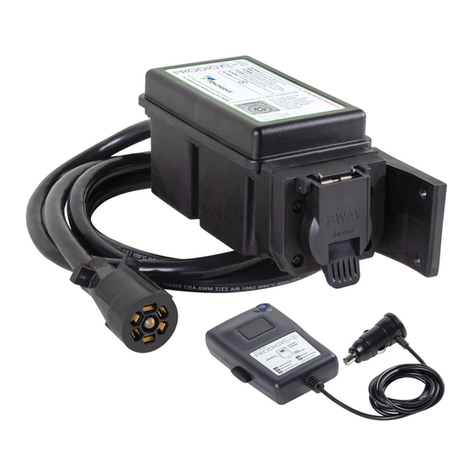
Tekonsha Prodigy RF User manual

Preferred
Mounting Location
Alternate Mounting
Locations
Cable Toward
Tow Vehicle
Prodigy® RF
Electronic Brake Control
For 2, 4 and 6 brake applications
READ THIS FIRST:
Read and follow all instructions carefully before
installing or operating the Prodigy RF. Keep these
instructions with the Brake Control for future
reference.
Components of Prodigy RF
A. Power Knob F. 7-Way cable to
B. Boost Button tow vehicle
C. Manual Override G. Connection to trailer
D. Display
E. Connector to
Auxiliary Power Port
Important Facts to Remember
1. WARNING The Prodigy RF may operate with reduced
performance if the Remote Hand Held Unit is removed
or disconnected while the trailer is in use.
2. Do not mount or activate RF generating items (cell
phones, two way radios) near (less than 12”) to the
Hand Held Unit or Power Module.
3. The Prodigy RF employs an inertial sensor. It senses
deceleration and generates an output that is based on
deceleration, thus the term “Proportional Braking”.
4. The Prodigy RF will “HOLD” your trailer with 25% of
power setting while you are at a standstill with brake
pedal applied for longer than 5-7 seconds.
5. The Prodigy RF will brake proportionally in reverse.
It will apply the appropriate brake voltage based on
deceleration.
6. WARNING The Gross Combined Weight Rating
(GCWR) must never exceed the vehicle manufacturers
recommendation.
7. CAUTION This control is not designed for use with
electric-hydraulic trailer brake systems.
8. CAUTION Do not submerge or immerse Prodigy RF
in water.
Installation Guide
Trailer Mount Power Module
Mounting Instructions
WARNING The Prodigy RF Power Module must
be securely mounted to the trailer frame. Failure to
install the Power Module within these constraints
may cause impaired performance.
The Power Module can be mounted to any suitable sur-
face on the trailer frame. The module cover should be
approximately level, within ±5 °, and above the trailer
frame rail. Preferred mounting location is on the side of
the trailer frame rail with the 8 foot cable towards the
tow vehicle.
1. Select a location so that the Power Module’s cover
is in the UP direction.
2. Use the four 1/4–14 x 1-1/4 self drilling screws
(provided) to drill into the trailer frame. Snug
screws securing Power Module. Tamper Resist
Washer Head Screws may be used for added
security.
3. Secure the excess 7-Way tow vehicle and trailer
wiring.
CAUTION Use of different screws may damage
the Power Module, or may not provide sufficient
mounting.
CAUTION Do not mount in a concealed location,
or inside a metal part of the trailer. Do not place
inside a utility box mounted on the trailer.
CAUTION Do not mount in a location that will
interfere with a load equalizing hitch.
Connecting Power Module
Your Prodigy RF Power Module has a molded
Bargman® 7-Way cable that will plug into the tow vehi-
cle. Refer to Wiring Diagram for location of pins and
function. When all connections are made, this connec-
tion supplies all power and signals to both the Power
Module and to the trailer. The trailer 7-Way cable is
connected directly to the 7-Way connector on the rear of
the Power Module. There is no additional wiring neces-
sary on the trailer.
WARNING Tow vehicle Must be Capable of pro-
viding 12V @ 20A for Electric Brake Applications,
Up to 6 brakes (3 axles).
CAUTION The Battery Charge to the trailer may
be temporarily disconnected (approximately 5 min-
utes) during braking if the total current to the Trailer
(Battery Charge and Electric Brake) exceeds 20
Amps. This allows for full brake power without
exceeding the tow vehicles wiring capacity.
Pin No. Function
1 Common Ground
2 Electric Brake
3 Tail & License
4 Battery Charge
5 Left Stop & Turn
6 Right Stop & Turn
7 Center Auxiliary
4
7
6
2
3
5
1
Remote Hand Held Unit
Plug the Hand Held Unit into any suitable 12V
Auxiliary Power Port in the vehicle.
• Remote Hand Held Unit must be within easy reach
of the operator.
• Do NOT operate with the Remote Hand Held Unit
disconnected.
NOTE: Some factory wired tow vehicles disconnect
the Battery Charge output in the 7-Way connector
when the ignition is turned off. This will turn off the
Power Module and the Hand Held Unit will display
n.c.
Display Readings after Connecting the Prodigy RF
Once the units are connected and successfully paired,
you should see the following on the two digit display:
• Initial Power to the Hand Held, without pairing or
• Power Module not powered or
• Paired, but Trailer is not connected to Power
Module.
• Power to Prodigy RF with trailer connected and
• Manual Override Activated without trailer connected.
• Manual Override activated (with trailer), 5.4 denotes
a hypothetical power output. This value is set using
the power knob. Range is 0.0 to 13 volts. This is an
indication of voltage output to electric brakes.
• Display will be blank during power saving mode (no
motion or braking
activity for at least 2
hours)
Boost
feature
engaged.
Boost
feature not
engaged.
(Blank
Display)
Pairing Instructions
Synchronization of the Remote Hand Held Unit to the
Power Module:
1. Connect trailer to tow vehicle.
2. Plug the Power Module 7-Way cable into the tow
vehicle.
3. Trailer’s 7-Way connector must be disconnected
from the Power Module.
4. Start vehicle’s engine. (Some vehicles require Key
On to supply power to the 7-Way connector or
Auxiliary Power Port)
5. Plug the Remote Hand Held Unit into an auxiliary
power source within easy reach of the operator.
6. Turn the Power Knob to minimum position,
Flashing 0.0.
7. Fully depress and hold both the MANUAL
OVERRIDE and BOOST BUTTON. The display
will start from P.5 and end at P.A.
Once P.A has been achieved, the Manual and Boost
can be released.
8. Press and hold the brake pedal until the display
shows flashing 0.0. for a correct pairing.
9. Set the Power Knob to greater than minimum.
Display now flashes n.c. (not connected).
10. Re-connect the Trailer 7-Way connector to the
Power Module. Display should now be .c.
(connected).
NOTE: To properly identify your trailer during
pairing, the 7-Way trailer plug must be disconnected
from the Power Module.
FLASHING
FLASHING
FLASHING
Automatic Leveling of the Sensor
The Prodigy RF will automatically acquire the proper
level setting of the tow vehicle and trailer combination
during the pairing operation.
to
Wiring Diagram
FLASHING
EG
F
D
C
BA
Remote Hand
Held Unit
Trailer Mount
Power Module

Adjusting the Power to the Trailer
Brakes (Prior to setting Boost)
Once the Power Module has been securely mounted to
the trailer frame and paired to the Hand Held Unit, it is
necessary to set the power needed to stop the trailer
during a braking event.
1. Connect trailer to tow vehicle.
2. Verify the Power Module to the Hand Held Unit
have been paired.
3. Verify that all tow vehicle and trailer cables have
been properly connected.
4. CAUTION Verify proper operation of all tow
vehicle and trailer lights prior to towing.
5. With the engine running, and the Manual Override
fully depressed, set the Power Knob to indicate
approximately 6.0, then release the Manual
Override.
6. Drive tow vehicle and trailer on a dry level paved
surface at 25 mph and fully apply Manual
Override.
If trailer brakes lock up:
Turn power down using power knob.
If braking was not sufficient:
Turn power up using power knob.
7. Repeat Step (6) until power has been set to a point
just below wheel lock up or at a force sufficient to
achieve maximum braking power.
8. Using the brake pedal, make a few low speed stops
to check the power setting. Trailer braking is initi-
ated and terminated via signals on the trailer
wiring, (Left and Right Turn and Stop). When the
brake pedal is released, the trailer braking will
cease.
(Boost Setting continued)
[
b
.I ], during a braking event, the power automatically
starts out at approximately 13% of the power setting and
increases with deceleration. With the boost on level 2,
[
b
.2 ], or with the boost on level 3, [
b
.3 ], during a
braking event, the power automatically starts out at
approximately 25% of the power setting and increases
with deceleration.
Some cases where you might want to use the boost button:
• You like the trailer braking to ‘LEAD’ the tow
vehicle’s braking
• Towing a full vs. empty trailer
• Degraded brake performance (most electric brakes
require manual adjustment - see Appendix A or a
dealer for adjustment or repair)
NOTE: Boost not intended to be used to take place of
trailer brake adjustment or repair.
See the chart below for recommended “Boost” settings
(indicated with X) for typical Trailer to Vehicle weight
relationships.
Select your boost setting based on your towing situation,
driving preference and condition of your trailer brakes.
Typical Boost Settings For Optimal Performance
(with properly adjusted trailer brakes*)
TRAILER WEIGHT compared to VEHICLE WEIGHT
Trailer weighs LESS than Vehicle
Trailer weighs APPROXIMATELY SAME as Vehicle
Trailer weighs UPTO 25% MORE than Vehicle
Trailer weighs UPTO 40% MORE than Vehicle
Trailer weighs OVER 40% MORE than Vehicle
XX
XXX
XXX
XX
X
WARNING
Do not exceed Gross
Combined Weight Rating (GCWR)
* Increased Boost setting may be needed if trailer brakes are worn, see Appendix A or a dealer for brake adjustment or repair
.
INCREASING BOOST LEVEL
BOOST “OFF”
Boost Setting
The boost button was designed to allow a more aggressive
setting for your trailer brakes and is available in three lev-
els - [
b
.I ], [
b
.2 ], [
b
.3 ]. Each incremental boost setting
increases the sensitivity of the Prodigy RF’s inertial sen-
sor, enhancing the participation of the trailer brakes during
a braking event.
The first press on the boost button displays the current set-
ting. Boost is advanced to the next level by continuing to
press the boost button.
Five seconds after setting the boost level, the display will
show
indicating Boost On by the right most decimal.
For example: With the boost off, [
b.
], during a braking
event, the power to the brakes starts out at zero and
increases with deceleration. With the boost on level 1,
Boost On
3. The power may need to be adjusted for different
load weights and road conditions.
4. Not all trailer brakes will lock up due to various
conditions. However, inability to lock up the
brakes generally indicates the need for an
inspection to determine the cause.
5. When the power is set correctly you should feel
unified braking between the trailer and tow
vehicle.
NOTE:
1. Always warm the trailer's brakes before
setting the power. Warm trailer brakes tend to be
more responsive than cold brakes. To warm trailer
brakes, drive a short distance (1/4 mile) at 45
MPH with manual lever engaged enough to cause
trailer braking at a low level.
2. WARNING The power should never be set high
enough to cause trailer brakes to lock up.
Skidding trailer wheels can cause loss of
directional stability of trailer and tow vehicle.

Display Situation Probable Cause
Sleep Mode
To conserve power, the Prodigy RF system will enter a
sleep mode 2 hours after there has been no movement
or braking activity on the Power Module or Hand Held
Unit.
Wake Up
1. Pressing the brake pedal in the tow vehicle or con-
necting/disconnecting the trailer from the Power
Module will wake up both the Power Module and
Hand Held Unit
2. The Hand Held Unit will wake up by any activation
of the Manual, Power or Boost. However, if the
Power Module does not have power or is discon-
nected, the Hand Held Unit will flash “n.c.” then
return to the sleep mode.
Troubleshooting Chart
Reverse
When backing a trailer you can cancel “BOOST” and
“HOLD” for a period of three minutes. This can be
accomplished by pressing the boost button continuous-
ly for five seconds with the brake pedal depressed. The
display will indicate:
(If “boost” was active, the right hand decimal point
will also be on.) After three minutes the “BOOST” and
“HOLD” features will automatically return to your
previous settings.
NOTE:
Returning to your previous settings prior to three min-
utes can be accomplished by pressing the boost button.
Flashes 2 times per second. Trailer is connected and Prodigy RF loses connection
to battery ground.
Flashes 2 times per second. Prodigy RF “sees” an overload condition during operation.
Flashes 2 times per second. 1. Prodigy RF sees brake wire short during idle condition.
2. Use of some test lights or non-Tekonsha testers
can cause this problem.
1. Power Module not connected to tow vehicle.
2. Trailer connector disconnected or corroded.
3. Key off or Loss of Battery Power from tow vehicle.
Flashes continuously 4. Trailer connected with open circuit on the brake line.
5. Loss of trailer brake magnet ground.
6. Loss of RF Communications, signal or interference.
7. Unit not paired or improperly paired.
No display with manual or pedal 1. Loss of power to Prodigy RF Hand Held Unit.
activation. 2. Loss of Ground to Prodigy RF Hand Held Unit.
3. Sleep mode. To wake up, press manual or boost button.
4. Blown fuse in Hand Held Power Plug.
No Braking Flashes Continuously Power control set to zero.
Power interruption while brake 1. Intermittent power connection in 7-Way connector.
pedal is depressed. 2. Power is applied while the manual or brake pedal
is depressed.
Pairing mode 1. Pairing mode
Flashing continuously 1. Unable to pair.
2. Trailer connected while in pairing mode. Temporarily
disconnect trailer from Power Module while P.A
is flashing.
3. Brake pedal not depressed during pairing.
4. Unable to recognize Left / Right Turn and Stop Signals.
(Blank
Display)
to
Appendix A: Trailer Brake Adjustment**
Appendix B: FCC Information
Brakes should be adjusted after the first 200 miles of
operation when the brake shoes and drums have “seated” and
at 3000 mile intervals, or as use and performance requires. The
brakes should be adjusted in the following manner:
1. Jack up trailer and secure on adequate capacity jack
stands. Follow trailer manufacturers recommendations
for lifting and supporting the unit. Check that the wheel
and drum rotate freely.
WARNING Do not lift or support trailer on any part of
the axle or the suspension system.
2. Remove the adjusting hole cover from the adjusting slot
on the bottom of the brake backing plate.
3. With a screwdriver or standard adjusting tool, rotate the
starwheel of the adjuster assembly to expand the brake
shoes. Adjust the brake shoes out until the pressure of the
Contains Transmitter Module
FCC ID: TBF-FREESTAR
WARNING This device complies with Part 15 of the FCC
Rules. Its operation is subject to the following conditions:
(1) This device may not cause harmful interference, and
(2) This device must accept any interference received,
including interference that may cause undesired operation.
To comply with FCC RF exposure requirements for mobile
transmitting devices, this transmitter should only be used or
installed at locations where there is at least 20 cm separation
distance between the antenna and all persons.
Appendix C: Patent Information
COVERED BY ONE OR MORE OF THE FOLLOWING:
U.S. PAT. 5741048, 6012780, 6068352, 6445993, 6615125
AU 716150, CA 2225644
OTHER PATENTS PENDING
linings against the drum makes the wheel very difficult to
turn.
Note: With drop spindle axles, a modified adjusting tool with
about an 80 degree angle should be used.
4. Then rotate the starwheel in the opposite direction until
the wheel turns freely with a slight lining drag.
5. Replace the adjusting hole cover and lower the wheel to
the ground.
6. Repeat the above procedure on all brakes.
WARNING Never crawl under your trailer unless it is
resting on properly placed jack stands.
Follow the trailer manufacturers recommendations for lifting
and supporting the unit. Do not lift or place supports on any
part of the suspension system.
**Note: Trailer Brake Adjustment procedures courtesy DexterAxle.
Other manuals for Prodigy RF
1
Other Tekonsha Controllers manuals
