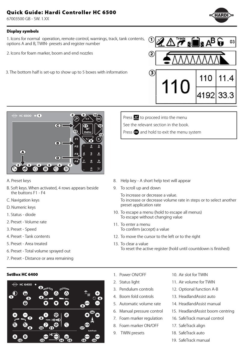
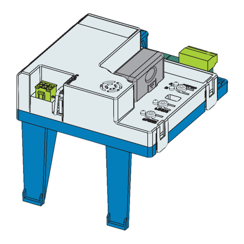
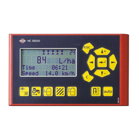
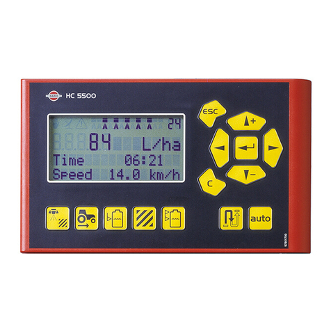
Hardi HC5500 User manual

CONTROLLER
HC5500
Service Manual – SW 4.XX
679060-702 – Version 7.02
GB – 11.2008
www.hardi-international.com

Page 2 of 87
Service Manual HC5500
Table of contents:
INTRODUCTION.................................................................................................................................................. 4
SPECIFICATIONS............................................................................................................................................... 5
HARDI HC5500 CONTROLLER:........................................................................................................................................5
HC5500, SPRAY BOX AND JOBCOM POWER SUPPLY AND PROTECTION ..............................................................................5
FUNCTIONS AND FUNCTIONALITY ................................................................................................................. 6
CONNECTORS AT THE BACK OF THE HC5500:....................................................................................................................6
SPRAYER CONNECTION:.....................................................................................................................................................7
Fluid cables..................................................................................................................................................................7
COMMANDER:...........................................................................................................................................................7
NAVIGATOR: ..............................................................................................................................................................7
NAVIGATOR or RANGER:..........................................................................................................................................7
Hydraulic cables..........................................................................................................................................................8
Commander with JobCom: ..........................................................................................................................................8
Navigator with JobCom:..............................................................................................................................................8
Commander, Navigator and Ranger without JobCom:................................................................................................8
Master..........................................................................................................................................................................8
AMP CONNECTORS ...........................................................................................................................................................9
OPTIONAL EXTRAS FOR THE HC5500 ..............................................................................................................................10
Printer........................................................................................................................................................................10
Foot pedal for main ON/OFF function......................................................................................................................11
SENSORS:.........................................................................................................................................................................12
Speed sensor for Tractor: Wheel, gearbox or radar..................................................................................................13
Pressure sensor..........................................................................................................................................................13
Fan speed on TWIN ...................................................................................................................................................14
TankGauge.................................................................................................................................................................15
End nozzle kit.............................................................................................................................................................17
EXTENDED MENU FOR SW 4.00..................................................................................................................... 18
Extended Menu 1 Language.......................................................................................................................................18
Extended Menu 2 Unit ...............................................................................................................................................18
Extended Menu 3 Sprayer type ..................................................................................................................................19
Extended Menu 4 Data exchange...............................................................................................................................20
Extended Menu 5 Optional sensors............................................................................................................................21
Extended Menu 6 Service interval..............................................................................................................................22
Extended Menu 7 Factory settings.............................................................................................................................22
Extended Menu 9 Jobcom..........................................................................................................................................26
TRACK SETTING IN EXTENDED MENU:........................................................................................................ 29
Menu E 8.4.1 Enable..................................................................................................................................................29
Menu E 8.4.2 Sensor test............................................................................................................................................29
Intellitrack rear sensor calibration:...........................................................................................................................30
Menu: E 8.4.3 Chassis...............................................................................................................................................32
Menu: E 8.4.4 Sprayer drawbar ................................................................................................................................32
SafeTrack on COMMANDER ....................................................................................................................................32
IntelliTrack on NAVIGATOR.....................................................................................................................................32
Menu E 8.4.5 Manual angling ...................................................................................................................................33
Menu E 8.4.6 Boom sensor ........................................................................................................................................33
Menu E 8.4.7 Error print...........................................................................................................................................33
Menu E 8.4.8 Minimum radius...................................................................................................................................33
Menu E 8.4.9 Half steer.............................................................................................................................................33
Select half steer for SPC/SPZ boom, only active with 2 boom sensors......................................................................33
Menu E 8.4.10 Safety factor.......................................................................................................................................33
Menu E 8.4.11 Boom type..........................................................................................................................................33

Page 3 of 87
LOOKAHEAD ...................................................................................................................................................................34
What is the LookAhead? ............................................................................................................................................34
How to use the LookAhead.........................................................................................................................................35
Calibration of LookAhead..........................................................................................................................................36
Pressure regulation valve for LookAhead..................................................................................................................36
SOFTWARE....................................................................................................................................................... 37
Software program for the controller..........................................................................................................................38
Communication cable ................................................................................................................................................40
USB to RS232 Converter............................................................................................................................................41
SOFTWARE UPLOAD HC5500........................................................................................................................ 44
SOFTWARE UPLOAD JOBCOM...................................................................................................................... 49
HANDLING THE CONFIGURATION FILE........................................................................................................ 55
Save the configuration file to the PC:........................................................................................................................55
Send the configuration file to the HC5500: ...............................................................................................................56
DUMP OF DATA FROM HC5500 CONTROLLER............................................................................................ 57
Configuration of HC5500 to dump data ....................................................................................................................57
DUMP DATA FROM HC5500............................................................................................................................ 59
CONFIGURATION OF HYPERTERMINAL....................................................................................................... 60
HANDLING DATA FROM HYPERTERMINAL ................................................................................................. 64
LOCAL LANGUAGE MAINTENANCE.............................................................................................................. 66
How to translate a language file................................................................................................................................66
New software and local language..............................................................................................................................66
Transfer the language file from PC to HC5500.........................................................................................................67
Download language file from HC5500 to PC:...........................................................................................................68
PCB’S ................................................................................................................................................................ 70
PCB for Liquid...........................................................................................................................................................70
Breakout PCB ............................................................................................................................................................70
PCB for section valves, 9 sections .............................................................................................................................71
PCB for section valves 13 sections ............................................................................................................................73
PCB for hydraulic......................................................................................................................................................74
PCB for SafeTrack.....................................................................................................................................................75
PCB for Jobcom.........................................................................................................................................................76
Resetting the Jobcom .................................................................................................................................................76
FAULT FINDING ON HC5500 & JOBCOM....................................................................................................... 77
LED´s on Jobcom.......................................................................................................................................................77
Thermal fuses on the HC5500 and Spray box............................................................................................................78
CABLES CONFIGURATION............................................................................................................................. 79
37–39 pole cable between Spray II and the JobCom / Breakout or 9 sec. PCB ........................................................79
37–39 pole cable between Hydraulic Box and the JobCom / Breakout PCB.............................................................80
DB37M–DB37F pole cable between JobCom / Breakout PCB to 13 sec. PCB.........................................................81
DB37M–DB37F pole cable between JobCom / Breakout PCB to 9 sec. PCB...........................................................82
DB25M–DB25F pole HY cable..................................................................................................................................83
Cable for LPZ/DH......................................................................................................................................................84
Cable for VHZ............................................................................................................................................................85
15F-15F DSUB Cable................................................................................................................................................86
REVISION.......................................................................................................................................................... 87

Page 4 of 87
Introduction
This manual covers the HARDI Controller 5500 and the options it supports like SafeTrack
on the Commander and IntelliTrack on Navigator.
It assumes the reader has knowledge of the more basic HC2500. The menu systems,
calibration and operations of the HC5500 are built up from the HC2500. The sensors used
are also similar or the same.
This manual also at times has notes on the HC6500. This is because the HC6500 is built up
around the HC5500 and has many similarities.

Page 5 of 87
Specifications
HARDI HC5500 Controller:
Display:
1. 4th line
2. 3rd line
3. Main Readout
4. Manual
5. External rate
6. Warning
7. Boom line status
8. Register no.
Navigation keys:
9. Multi function keys
Readout presets &
Short cuts:
10. Auto On
11. Remaining Distance
or Area
12. Volume used
13. Area covered
14. Tank volume
15. Speed
16. Volume rate
HC5500, Spray box and JobCom power supply and protection
Power supply:
Operating range: 9-16V DC
Controlled processor shut down: < 9 VDC
Protected against over voltage: 28 VDC
The electronics are protected against reverse polarisation of the power input.
Ambient temperature: – 5°C to + 70°C
Memory: Flash PROM non-volatile
Analog transducers typ. press. (Option 1):
Supply: 12 V
Input: 4 to 20 mA
Minimum speed for volume regulation: 0.5 km/h
Digital transducers type fan speed (option 2): Square signal
Frequency: 0.5 Hz to 2 kHz
Trigger high: 4.0 to 12.0 Volt DC
Trigger low: 0.0 to 2.0 Volt DC

Page 6 of 87
Functions and functionality
Connectors at the back of the HC5500:
The connector’s functions are:
A: COM 1:
This can be used for dumping data, receiving data or for the connection to the printer. Use
COM 1 for software updates.
B: COM 2:
This has the same function as COM 1, though not for software updates.
C: Control box:
This is used for the liquid control box Spray I or Spray II box.
D: AUX:
This is used if the tractor speed sensor or the foot pedal is connected to the HC5500.
Harness P/N 28027600 is necessary.

Page 7 of 87
Sprayer connection:
Fluid cables
Cables details can be found in the cables configuration chapter.
COMMANDER:
1. HC2500/5500
2. Spray II
3. Hydraulic Box
4. Cable: 26004200 L=17,5m
28028700 L=14m
28027500 L=11,5m
28028900 L=8m
28028800 L=5m
26003900 L=2m
26028300 L = 0,5m
5. JobCom or Breakout PCB
6. Cable P/N 26004900
7. 13 sec PCB P/N 26004800
NAVIGATOR:
1. HC5500
2. Spray II
3. Hydraulic Box
4. Cable P/N: 26004200 L = 17,5m
28028700 L=14m
28027500 L=11,5m
28028900 L=8m
28028800 L=5m
26003900 L=2m
26028300 L = 0,5m
5. JobCom
6. Cable P/N 26023800
7. 9 sec PCB P/N 72173900
NAVIGATOR or RANGER:
1. HC2500/5500
2. Spray II
3. Hydraulic Box
4. Cable: 26004200 L = 17,5m
28028700 L=14m
28027500 L=11,5m
28028900 L=8m
28028800 L=5m
26003900 L=2m
26028300 L = 0,5m
7. 9 sec PCB P/N 72173900

Page 8 of 87
Hydraulic cables
Cables details can be found in the cables configuration chapter.
Commander with JobCom:
1. HC5500
2. Spray II Box
3. Hydraulic Box
4. Cable P/N: 72236600, L=5m
72236400, L=8m
5. JobCom with DAH Interface
6. Cable P/N 26016900
7. Hydraulic junction box
9. SafeTrack and lock cable P/N26024000
Navigator with JobCom:
1. HC5500
2. Spray II Box
3. Hydraulic Box
4. Cable P/N: 72236600, L=5m
72236400, L=8m
5. JobCom DAH Interface
6. Cable P/N 26016900
7. Hydraulic junction box
10. IntelliTrack cable P/N26024100
Commander, Navigator and Ranger without JobCom:
1. HC5500
2. Spray II Box
3. Hydraulic Box
4. Cable P/N: 26008400, L=8m
6. Cable P/N 26016900
7. Hydraulic junction box
11. Breakout PCB
Master
1. HC5500
2. Spray II Box
3. Hydraulic Box
4. Cable P/N: 72168100, L=8m
72278300, L=12m
7. Hydraulic junction box

Page 9 of 87
AMP connectors
The AMP connectors have each of the legs numbered so they are easy to identify. The
table shows how the wires are mounted in the plug and what function the wires have.
AMP plug Pin & Wire connection
AMP Super Seal Function Colour
2 + Brown
3 Signal Blue
1 - Black

Page 10 of 87
Optional extras for the HC5500
Printer
A printer can be fitted for the HC5500, as shown on Picture 1.
Picture 1: Printer for the HC5500
The printer can print out several kinds of data from the HC5500.
Picture 2 is an example of a printed register and Picture 3 a printed configuration.
Register printout gives the user sprayed area, volume rate that has been used etc.
The configuration print is very useful for a quick overview of how the controller is set up and
for spotting errors.
Picture 2: Print of the register Picture 3: Print of the configuration
Printer

Page 11 of 87
The connection from the printer to the HC5500 is done through COM 1 or COM 2. The
printer is powered through the COM port so there is only one plug for the connection.
The configuration of the com port is done in Extended Menu 4.
In menu E4.1.1 Equipment type, Printer must be chosen and in menu E4.1.2 the baud rate
must be set to 9600.
In the section "Configuration of HC5500 to dump data” is a detailed description of the setup.
If the printer does not work, then check the connection to the COM port and see if it is
correct.
If it does not print, check the paper is threaded correctly (not reverse side).
Foot pedal for main ON/OFF function
The foot pedal is an extra option for the HC5500. The pedal is connected through the wire
harness that can be seen on Picture 4 and Picture 5.
The wire harness is plugged into the AUX connector.
The “Speed2” connector has GND on pin1, +12V on pin 2 and Speed signal on pin 3.
The “Switch” connector has GND on pin 1, +12V on pin 2 and Switch signal on pin 3.
Picture 4: Foot pedal for the HC5500 Picture 5: Wire harness for the HC5500
The setup of the foot pedal to the HC5500 is done in E8.5.1. The menu tree can be seen in
section “Extended Menu 8”. There are two choices depending on the switch type.
The HC5500 can be set to a toggle or a pulse function. The standard HARDI foot pedal is a
toggle type.

Page 12 of 87
Sensors:
Angle sensor Sensor AMP Con PCB
Blue Signal Signal 3Signal
Black GND GND 1-
Brown +12V +12V 2+
Speed, TWIN, Boom and SafeTrack lock
sensor
Hardi P/N 28047500
Type: Inductive
Range: 0-8mm
Signal: 0-200Hz
Operation indicator: Yellow light when
active (0,8V)
Power: 12V
Visual indicator: LED to indicate active
status
Hardi Pin assignment: Brown +
Blue signal
Black -
Front angle sensor:
Hardi P/N 26005700
Type: Potentiometer
Range: 0-70°
Signal: 0,5 - 4,5V
Centre position: 2,5 V
Power: 12V
Hardi Pin assignment: Brown +
Blue signal
Black -
SafeTrack rear sensor:
Hardi P/N 26005800
Type: Potentiometer
Range: 0-120°
Signal: 0,5 - 4,5V
Centre position: 2,5 V
Power: 12V
Hardi Pin assignment: Brown +
Blue signal
Black -

Page 13 of 87
Flow sensor:
Hardi P/N 72117500
Type: Inductive
Range: On, 0,2-0,5 V
Off, 6,5-7,0 V
Visual indicator: Red light at Off (0,8V)
Power: 12V
Hardi Pin assignment: Brown +
Blue signal
Black -
Pressure sensor:
Hardi P/N 842022
Type: Pressure
Range: 0-10 Bar
Signal: 4-20mA
Power supply: 8-30V
Hardi pin assignment: Brown +
Blue Signal
Black N/C
Speed sensor for Tractor: Wheel, gearbox or radar
The HC5500 can have several different kinds of speed sensors. It can have an inductive
sensor mounted on the back wheel, the same sensor as on the trailed sprayers, or it can be
connected to the tractors speed sensor, in the gearbox, or radar.
The sensors are connected to the HC5500 through wire harness on
Picture 5.
The signal from the tractor or the radar must be between 0 - 5 Volt and below 2,000 Hz.
Most radar’s have this signal range.
The signal from the tractors can however change a lot from brand to brand; consult your
manual or tractor dealer for more information.
The setup of the speed sensors in the HC5500 is done in the menu 3.1. Further instructions
about the connection and calibration can be found in the instruction book.
Pressure sensor
An optional 4 to 20 mAmp pressure sensor can be fitted to the liquid system.
With the sensor, the controller can switch to pressure based regulation when the flow drops
below the minimum rate measurable by the flow meter. Preventing LookAhead from winding
the pressure regulation valve down too far when driving very slowly.
In menu E8.1.7 the sensor has to be set to “Active”.
The sensor can be set for a minimum pressure. If the pressure drops below the set value,
pressure regulation stops.
The HC5500 has min and max pressure alarm that will be shown in the display menu.
The cable is connected to the “PCB for section valves”.

Page 14 of 87
The version of the PCB used depends of what type of sprayer the sensor in mounted on.
For the wire connections to the PCB, see section “PCB’s” on pages 70.
When the pressure sensor is mounted on the sprayer, the HC5500 is setup to the sensor. In
menu “5” on pages 21, the setup is shown.
The pressure sensor has a fixed measuring range in Bar or PSI.
In Menu E5.1.1 the minimum value is typed in and in menu E5.1.2 the maximum is typed in.
The measuring range is written on the pressure transducer. Our standard is 0 to 10 Bar.
Note that the sensor is ignored if the minimum input is less than 3 mAmp.
In menu E8.1.3 is the minimum allowed pressure typed in. In practice, this means the
regulation will stop if the pressure goes below this value.
These setting are done in the Extended Menu.
For a readout, the sensor must be setup. In Menu 2.1 Display readout / Optional sensor
Menu 2.1.3, the pressure sensor is chosen so the actual pressure can be seen.
Fan speed on TWIN
The Fan speed sensor can measure the revolutions on the blower unit on a TWIN sprayer.
The sensor is mounted on blower as shown in Picture 6.
For connecting the wiring from the Fan speed sensor see section “PCB’s” on pages 70.
Picture 6 Fan speed sensor
When the Fan speed sensor is mounted and the wires are connected, the HC5500 must be
setup for the sensor. In menu E5.2 the PPU value is set. The PPU value can be seen in the
menu E5.2.1. The default value is 1.
For a reading on the HC5500 display, the Fan speed sensor must be setup for the display.
In Menu 2.1, Display readout / Optional sensor, Menu 2.1.3, is the Fan speed sensor
chosen so the fan r/min can be seen.
Note the following for the Linak actuators on the TWIN FORCE sprayers
Spray II box &
Linak actuator AMP
connector Linak
Part no. Voltage
(min to max stroke) Signal
Breakout PCB 4 pin 262034 1.0 to 5.0 V Analogue
JobCom PCB 4 pin 262034 1.0 to 12.0 V PWM (Hz)

Page 15 of 87
TankGauge
The TankGauge (digital contents sensor) is a sensor that can measure how much liquid is in
the tank. It has no automatic function. It can give a warning when the tank is about to run
dry.
Connecting TankGauge
Wire between JobCom and 26007300
Figure 1 Wire for connection between JobCom and TankGauge
The cable is fitted with an AMP plug and three lose wires at the other end. It is attached to
the JobCom at J1, “Tank gauge”.
For JobCom with hardware version before 2.0, a 10Kohm resistor is fitted between
connector 2 & 3 on the JobCom.
Figure 2 shows the resistor location.
Figure 2 Mounting of the 10 K ohm resistance in the JobCom
Models without JobCom:
A. TankGauge is mounted on PCB in
distribution valves junction box.
Green/Grey wire is connected to the
blue wire from TankGauge.
B. Is mounted in OPT 1 as shown.
Brown wire +
Black wire –
If a speed sensor is present, connect
it in parallel.
Distribution Valves Junction Box
The cable from the Spray box has two lose wires which are not connected in the JobCom.
These much be attached to the plug as shown on Picture 7
AMP Super Seal PCB Wire Wire (old version)
2 + Brown Green
3 Sig Blue White
1 - Black Brown
- Signal +
Blue
wire
Black
wire Brown
wire
A B

Page 16 of 87
Picture 7 Connection of the two wires from Spray box cable
The sensor is mounted on the back side of the sump of the tank.
Settings in the HC5500
“Extended Menu 5 Optional sensors" is the setup menu. In Menu E5.3.1 chose “HARDI”.
To check the connections, the frequency with an empty tank can be checked.
Menu 4.5.3.3, Tank Gauge, should read be between 100 and 200 Hz.
How does it work?
The TankGauge sensor measures the pressure created by the water in the tank. The
sensor sets data points for each 25 mm of water level. 100 data points are available. The
data points are registration marks where the tank sensor registers the pressure and
therefore how much water there is left in the tank at this water level.
The data points can be seen in Menu E8.2.3. They can also be edited in this Menu.
For setting the data points, the flow sensor must first be calibrated.
Next step is to fill the tank completely with a known quantity of water.
When the calibration starts, the flow sensor will register how much water is sprayed out and
the tank sensor will register the pressure for every 25 mm water level until the tank is empty.
At the end of the calibration, the actual verses the theoretical quantity of water is set just like
doing a “Tank Method” calibration of the nozzles. This will fine tune the flow sensor PPU.
The calibration of the TankGauge is described in the instruction book.
When the TankGauge is used in use, there are two modes:
•When the sprayer is moving
•When the sprayer is stationary
When the sprayer is moving, the HC5500 will calculate an average value of the read out
from the TankGauge. The average value is necessary because of the movement of the
liquid in the tank will when the sprayer is moving. If a not averaged value was shown, the
readout would be useless for the driver.
When stationary, the value is not averaged. The movement of the liquid in the tank should
stop and the average value is therefore not necessary.
Left side = Green/Gray
Right side = Pink/Yellow

Page 17 of 87
End nozzle kit
The End nozzle kit is connected to the “PCB for section valves”, seen on page 71. For
accurate boom width whilst using the end nozzles, Menu 3.3.4 needs to be set up. For more
information, see in the instruction book for the HC5500.
Picture 8 End Nozzle kit

Page 18 of 87
Extended Menu for SW 4.XX
To access Extended Menu, press and hold the “ESC” button, switch the power ON and wait
until the menu is opened.
The “[xxx]” indicates the choices or range.
The factory default and helpful notes like increments of change are in italics.
Extended Menu 1 Language: Here the is language choice. There are standard languages
and place for two local languages that can be uploaded to the HC5500 by a service person.
Note: For Russian, the HC5500 hardware version with Cyrillic text is used.
Extended Menu 2 Unit: Is for what unit the controller shall use.
Extended Menu 3 Sprayer type: The basis setup of what kind of sprayer is the HC5500
attached to and what kind of liquid system is mounted on the sprayer.
Extended Menu 4 Data exchange: Setup of the data communication.
HC5500 can be attached to other units like a PC, printers, variable Rate Application or
remote control. The communication between the HC5500 and the unit has to be set up
correctly.
The setup and use of the com ports are described in the “Software” section of this manual.
Extended Menu 5 Optional sensors: Setup of optional sensors that can be fitted. It is
typically the pressure, fan revolutions and tank contents (TankGauge).
Extended Menu 6 Service interval: Setup of the service interval.
Extended Menu 7 Factory settings: Setup of factory settings
Extended Menu 8 Settings: Settings of the regulation, tank, track and misc. settings are
done.
Extended Menu 9 JobCom: Is for setup of the JobCom, TWIN actuators and read out of
the software version and serial number.
Extended Menu 1 Language
E1 Language [UK, D, DK, F, SF, HU, Local 1, Local 2]
Default is UK.
Local 1 & 2 are languages that can be added with a PC and the “HC 5500 Language config”
software or another HC5500.
Extended Menu 2 Unit
E2 Unit [Metric, US]

Page 19 of 87
Extended Menu 3 Sprayer type
E3.1 Field sprayer E3.1.1 Liquid system
[Equalization, Not equalization, Circulation]
Default is Equalization.
Equalization = System with liquid return to tank from
section valves; e.g. EVC.
Not equalization = System without returns to tank;
e.g. EFC on CM05.
Circulation = System where liquid constantly
circulates in the boom lines.
E3.1.2 Dual Line
E3.1.2.1 System type
[Not present, 2 stage, 3 stage]
Default is Not present.
2-stage: Line A will always be open, and Line B can
be switched on and off automatically.
3-stage: Line A switches to B, then Line A comes on
so both A & B are on.
E3 Sprayer
type E3.1.2.2 Sensor type
[Pressure, Speed]
If a pressure transducer is fitted, pressure is used to
trigger the line change.
E3.1.2.3 System lag
[Second]
Default is 1.0 sec.
System lag prevents oscillation when spray lines
change.
E3.1.2.4 Line overlap
[Second]
Default is 1.5 sec.
System overlap allows the activated spray line to
stabilise before the other line is turned off.
E3.2 Mistblower E3.2.1 Liquid system
[Equalization, Not equalization, Circulation]
Default is Equalization.
Equalization = System with liquid return to tank from
section valves; e.g. EVC.
Not equalization = System without returns to tank;
e.g. Solenoid controls.
Circulation = System where liquid constantly
circulates in the boom lines
E3.2.2 Sub unit
[Standard, UCR]
Default = Standard (UCR affects menu 3.3)
UCR = Unit Canopy Row. Bases application on the
size of the tree canopy.

Page 20 of 87
Extended Menu 4 Data exchange
E4.1 COM 1
setup E4.1.1 Equipment type
[Printer, Dump, Printer & dump, GSM,
VRA/remote]
Dump is for data transfer to a PC via for
example Microsoft HyperTerminal.
GSM is not used.
Variable Rate Application/remote is signal from
an external source.
E4 Data
exchange E4.1.2 Baud rate
[19200, 9600, 4800, 2400, 1200]
Default is 9600.
Use 9600 for HARDI 12 volt printer.
E4.1.3 Protocol select
[HARDI VRA proto.]
Only one protocol available at the moment.
E4.2 COM 2
setup E4.2.1 Equipment type
[Printer, Dump, Printer & dump, GSM,
VRA/remote]
Dump is for data transfer to a PC via for
example Microsoft HyperTerminal.
GSM is not used.
Variable Rate Application/remote is signal from
an external source.
E4.2.2 Baud rate
[19200, 9600, 4800, 2400, 1200]
Default is 9600.
Use 9600 for HARDI 12 volt printer.
E4.2.3 Protocol select
[HARDI VRA proto.]
Only one protocol available at the moment.
Other manuals for HC5500
6
Table of contents
Other Hardi Controllers manuals
Hardi
Hardi HC 5500 SPRAY BOX III User manual
Hardi
Hardi COMMANDER 5500 User manual
Hardi
Hardi HC5500 User manual
Hardi
Hardi HC 9600 User manual

Hardi
Hardi HC5500 User manual

Hardi
Hardi HC5500 User manual
Hardi
Hardi ISOBUS VT User manual
Hardi
Hardi HC 2500 Series User manual
Hardi
Hardi HC 8500 User manual

Hardi
Hardi HC5500 User manual
