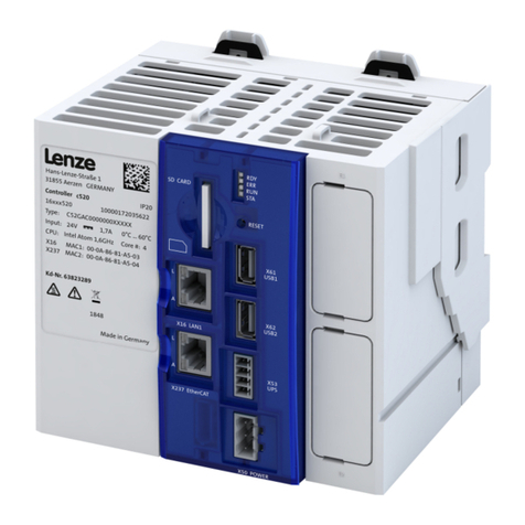
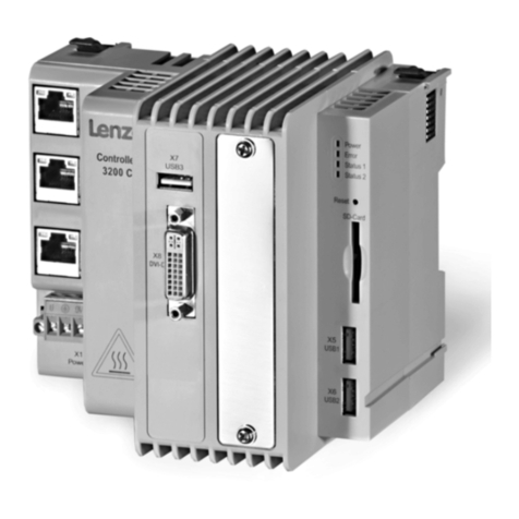
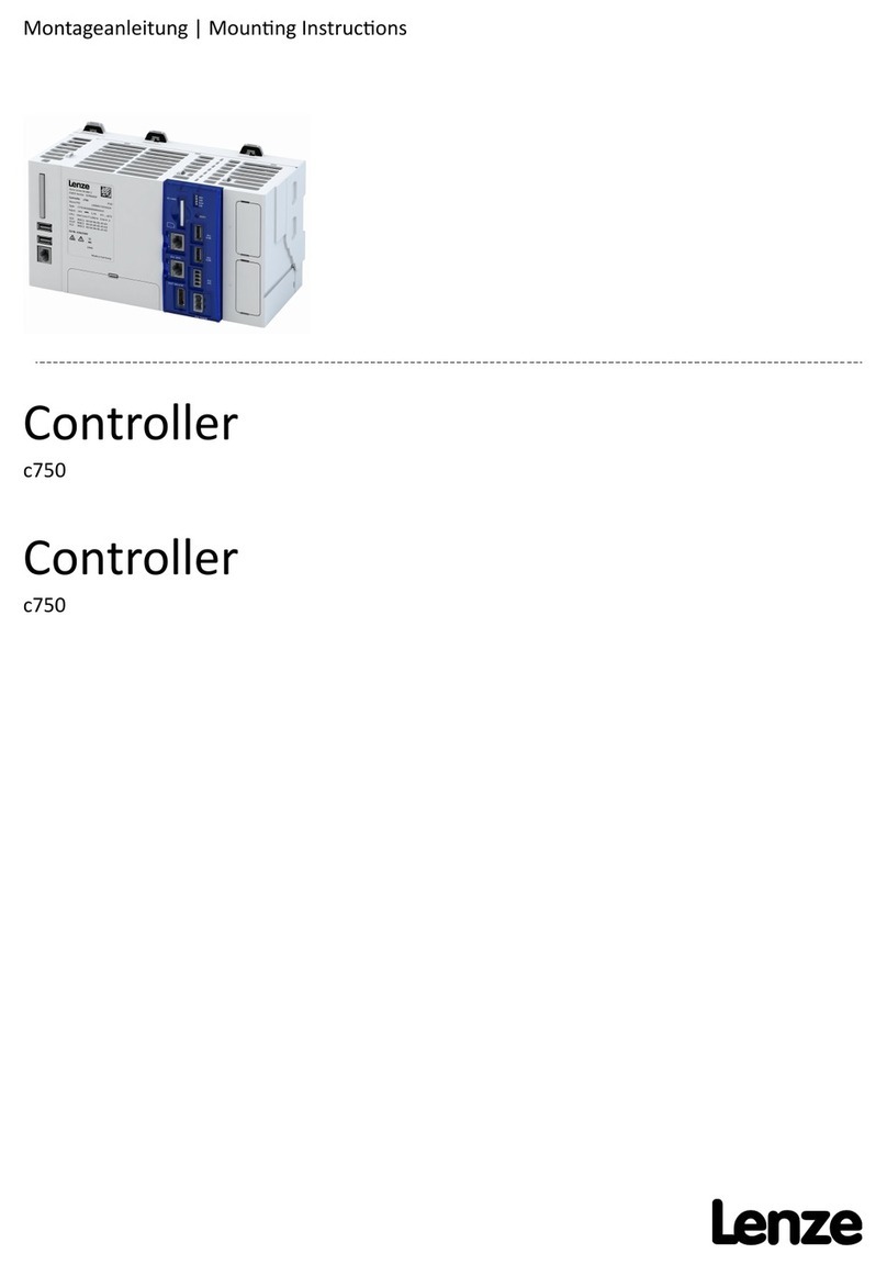
Lenze c250-S User manual

Safety-Controller c250-S, Safety-Buskoppler, Safety-I/O-Modul
Safety controller c250-S, Safety bus coupler, Safety I/O-module
Montageanleitung | Mounng instrucons


Über dieses Dokument
WARNUNG!
Lesen Sie diese Dokumentaon sorgfälg, bevor Sie mit den Arbeiten beginnen.
▶Beachten Sie die Sicherheitshinweise!
Detaillierte Informaonen nden Sie in den Betriebsanleitungen zu den Modulen.
Informaonen und Hilfsmiel rund um die Lenze-Produkte nden Sie im Internet:
hp://www.lenze.com à Download
Über dieses Dokument
3

Sicherheitshinweise
Nur qualiziertes Personal darf Arbeiten mit dem Produkt ausführen.
•Qualiziertes Personal, das mit den einschlägigen Sicherheitskonzepten zur Funkonalen Sicherheit sowie
den geltenden Normen und Vorschrien vertraut ist.
•Qualiziertes Personal, das Sicherheitseinrichtungen für Maschinen und Anlagen plant, entwickelt, ein-
baut und in Betrieb nimmt.
•Qualiziertes Personal im Sinne der sicherheitstechnischen Hinweise dieser Anleitung sind Personen, die
aufgrund ihrer Ausbildung, Erfahrung und Unterweisung sowie ihrer Kenntnisse über einschlägige Nor-
men, Besmmungen, Unfallverhütungsvorschrien und Betriebsverhältnisse berechgt sind, die jeweils
erforderlichen Tägkeiten auszuführen und dabei mögliche Gefahren erkennen und vermeiden können.
Grundlegende Sicherheitsmaßnahmen
Beachten Sie:
•Spannungsversorgung 24 V DC nur durch ein sicher getrenntes Netzteil ( SELV /PELV).
Geräteschutz
•Alle steckbaren Anschlussklemmen nur im spannungslosen Zustand aufstecken oder abziehen.
•Verdrahtungen an Anschlüssen nur im spannungslosen Zustand verändern.
•Das Produkt nur im spannungslosen Zustand aus der Installaon enernen.
Sicherheitshinweise
Grundlegende Sicherheitsmaßnahmen
4

Produknformaon
Produktbeschreibung
Mit Safety‑Controller c250-S können sichere Eingänge, sichere Ausgänge und FSoE-Geräte einer Anlage/
Maschine verbunden werden. Zerzierte Funkonsbausteine ermöglichen die Verknüpfung der Signale zu
einem Sicherheitsprogramm.
Safety‑Controller c250-S ist modular aufgebaut und besteht aus diesen Komponenten:
•Safety‑Controller c250-S (= PLC)
•Safety‑Buskoppler (= Netzwerkanschluss)
•Safety‑I/O‑Modul (= Sichere Eingänge/Ausgänge)
Unterstütztes Netzwerk:
•EtherCAT® mit Safety-over-EtherCAT (FSoE = Fail Safe over EtherCAT)
Die Benennung des Produktes
Produktcode
C 25 B A Y □□□
Produktart Controller C
Produkamilie c250-S 25
Produktgeneraon Generaon 1 B
Montageart Schaltschrankmontage A
Kennung Zubehör Automaon Y
Modulfunkon Safety-Controller SQ
Safety-Buskoppler CB
Safety-I/O-Modul A42
nicht relevant -
Beispiel
Produktcode Bedeutung
C25BAYSQ Safety-Controller c250-S
Produknformaon
Produktbeschreibung
5

Ausstaung
Safety-Controller c250-S
E-Bus
E-Bus (seitlich)
Kennzeichnungsfeld
Entriegelung
zusätzlicher
Schirmanschluss
Hutschienen-
befesgung
Status- sLED
(abgedeckt)
Funkonserde
Safety-I/O-Modul
E-Bus
E-Bus (seitlich)
Kennzeichnungsfeld
Entriegelung
Adressschalter
zusätzlicher
Schirmanschluss
Hutschienen-
befesgung
Status- sLED
Anschlussleiste
IO LED-s
(abgedeckt)
(seitlich)
Funkonserde
Safety-Buskoppler
E-Bus
Kennzeichnungsfeld
zusätzlicher
Schirmanschluss
Hutschienen-
befesgung
Status- sLED
Netzwerk Out
Netzwerk In
(abgedeckt)
24-V-Anschluss
Funkonserde
Produknformaon
Ausstaung
6

Montage/ Installaon
Mechanische Installaon
Safety‑Controller c250‑S ist für die Montage auf einer 35 mm Hutschiene ausgelegt. Über den integrierten E-
Bus werden die Module dabei elektrisch gekoppelt.
Gruppen bis zu 3 Modulen können zunächst über den E-Bus elektrisch gekoppelt werden und anschließend
auf eine Hutschiene gesetzt werden. Größere Einheiten sollten als einzelne Module oder in Gruppen auf
eine Hutschiene gesetzt werden. Erst danach durch seitliches Verschieben die elektrische Koppelung über
den E-Bus herbeiführen.
Beim Koppeln der Module wird die elektrische Verbindung durch eine mechanische Verrieglung gesichert.
Zum Freigeben der mechanischen Verriegelung ist beim Trennen von Modulen die Entriegelung zu drücken.
So gehen Sie vor:
Modul auf eine Hutschiene setzen
1. Modul zur Hutschiene führen und untere Kante ansetzen.
2. Modul nach oben drücken ①
3. Modul zur Hutschiene kippen ②
4. Modul nach unten gleiten lassen und dabei oben einhaken ③
Das Modul sitzt fest auf der Hutschiene und lässt sich seitlich noch verschieben.
Module anreihen
1. Schutzabdeckung vom E-Bus enernen
2. Die Module wie beschrieben auf die Hutschiene setzen.
3. Module seitlich so verschieben, dass der E-Bus kontakert.
4. Verriegelung muss hörbar einrasten!
Die Module sind über den E-Bus gekoppelt.
③
①
②
Montage/ Installaon
Mechanische Installaon
7

Abmessungen
Die Abmessungen in mm gelten für:
Safety-Controller c250-S Safety-Buskoppler Safety-I/O-Modul
C25BAYSQ C25BAYCB C25BAYA42
Montage/ Installaon
Mechanische Installaon
Abmessungen
8

Elektrische Installaon
Sind die Module mechanisch monert, kann die elektrische Installaon ausgeführt werden.
Wurde die Verdrahtung mit den Steckern bereits vorbereitet, müssen nur noch die Stecker in die Module
gesteckt werden.
Die Verdrahtung kann auch an gesteckten Steckern ausgeführt werden.
Verschaltung mit den zugehörigen Steckern vervollständigen.
Am Safety-Buskoppler die Stecker:
•24 V DC
•Netzwerk In
•Netzwerk Out (wenn verwendet)
Safety-Controller (PLC):
•Keine Verdrahtung erforderlich! 24 V DC über den E-Bus.
Am Safety-I/O-Modul die gemeinsame Steckerleiste:
•24 V DC
•Sichere Eingänge
•Sichere Ausgänge
Eine Erweiterung mit I/O-Modulen ist möglich.
Sind mehrere gleiche Module in einem Umfeld verbaut, ist auf die richge Zuordnung zu achten.
"
. . . . . .
E-Bus
E-Bus
C25BAYSQ
"
. . . . . .
E-Bus
E-Bus
DC SELV PELV 24 V /
(+19.2 … +28.8 V)
L-
L+ 15
14 13
12 11
10 9
8 7
6 5
4 3
2 1
0
C25BAYA42
"
E-Bus
L-
L+
24 V
IN
OUT
EtherCAT
C25BAYCB
DC SELV PELV 24 V /
(+19.2 … +28.8 V)
. . . . . .
SIB
SIA
. . .
,
Montage/ Installaon
Elektrische Installaon
9

Inbetriebnahme
Zur Inbetriebnahme des Safety Controller c250-S benögen Sie:
•Lenze Controller als EtherCAT-Master
•»LENZE PLC-Designer« ab V3.14
•Ordnungsgemäß monerte und verdrahtete Module
-mindestens die Versorgungsspannung 24 V DC
•Kontrolle über angeschlossene Sensoren
Erstes Einschalten
Beachten Sie die Betriebsanleitung zum Safety Controller c250-S.
Inbetriebnahme
Erstes Einschalten
10

About this document
WARNING!
Read this documentaon carefully before starng any work.
▶Please observe the safety instrucons!
Detailed informaon can be found in the operang instrucons for the modules.
Informaon and tools with regard to the Lenze products can be found on the Internet:
hp://www.lenze.com à Download
About this document
11

Safety instrucons
The product must only be used by qualied persons.
•Qualied persons who know the applicable concepts of funconal safety as well as the relevant standards
and regulaons.
•Qualied persons who plan, design, install and put machine and system safety equipment into operaon.
•Qualied persons within the meaning of the safety instrucons of the operang instrucons are all per-
sons whose training, experience, instrucons and knowledge of the applicable standards, codes, accident
prevenon regulaons and operang condions authorise them to perform the required work and ena-
ble them to recognise and avoid potenal hazards associated with that work.
Basic safety measures
Please note the following:
•Voltage supply 24 V DC only through safely separated power supply unit (SELV/PELV).
Device protecon
•Connect/disconnect all pluggable terminals only in deenergised condion.
•Only change wiring on connecons in deenergised condion.
•Only remove the product from the installaon in deenergised condion.
Safety instrucons
Basic safety measures
12

Product informaon
Product descripon
A Safety‑Controller c250-S serves to connect safe inputs, safe outputs and FSoE devices of a system/
machine. Cered funcon blocks enable the signals to be linked to form a safety program.
A Safety‑Controller c250-S has a modular structure and consists of the following components:
•Safety‑Controller c250-S (= PLC)
•Safety‑bus coupler (= network connecon)
•Safety‑I/O‑module (= safe inputs/outputs)
Supported network:
•EtherCAT® with Safety-over-EtherCAT (FSoE = Fail Safe over EtherCAT)
The name of the product
Product code
C 25 B A Y □□□
Product type Controller C
Product family c250-S 25
Product generaon Generaon 1 B
Mounng type Control cabinet mounng A
Idencaon Automaon accessories Y
Module funcon Safety Controller SQ
Safety bus coupler CB
Safety I/O module A42
not relevant -
Example
Product code Meaning
C25BAYSQ Safety Controller c250-S
Product informaon
Product descripon
13

Equipment
Safety Controller c250-S
Funconal earth
(covered)
Status LEDs DIN rail
mounng
Addional
shield connecon
Unlocking mechanism
Marking area
(lateral)
E-bus
E-bus
Safety I/O module
Funconal earth
(lateral)
(covered)
IO LEDs
Terminal strip
Status LEDs DIN rail
mounng
Addional
shield connecon
Address switch
Unlocking mechanism
Marking area
(lateral)
E-bus
E-bus
Safety bus coupler
Funconal earth
24-V connecon
(covered)
Network In
Network Out
Status LEDs DIN rail
mounng
Addional
shield connecon
Marking area E-bus
Product informaon
Equipment
14

Mounng/ installaon
Mechanical installaon
A Safety‑Controller c250‑S is designed to be mounted to a 35 mm DIN rail. The integrated E-bus serves to
couple the modules electrically.
Groups up to three modules can be rst coupled electrically via the E-bus and then placed onto a DIN rail.
Bigger units should be placed onto the DIN rail as individual modules or in groups. Only then, move the
modules sideways to provide for an electrical coupling via the E-bus.
When the modules are coupled, the electrical connecon is secured by a mechanical locking. In order to
release the mechanical locking, press the unlocking mechanism for separang the modules.
How to proceed:
Place the module onto a DIN rail
1. Guide the module to the DIN rail and put on the lower edge.
2. Push the module upwards ①
3. Tip the module towards the DIN rail ②
4. Let the module slide downwards and let it hook on top ③
The module is placed rmly on the DIN rail and can sll be moved sideways.
Mounng the modules side by side
1. Remove protecve cover from the E-bus
2. Place the modules onto the DIN rail as described.
3. Move the module sideways so that the E-bus is contacted.
4. The locking mechanism must click into place audibly!
The modules are coupled via the E-bus.
③
①
②
Mounng/ installaon
Mechanical installaon
15

Dimensions
The dimensions in mm apply to:
Safety controller c250-S Safety bus coupler Safety I/O-module
C25BAYSQ C25BAYCB C25BAYA42
Mounng/ installaon
Mechanical installaon
Dimensions
16

Electrical installaon
If the modules are mounted mechanically, the electrical installaon can be carried out.
If the wiring with the plugs has already been prepared, only the plugs must be plugged into the modules.
Wiring can also be carried out at plugged plugs.
Complete wiring with the respecve plugs.
At the safety bus coupler, these are the plugs for:
•24 V DC
•Network In
•Network Out (if used)
Safety Controller (PLC):
•No wiring required! 24 V DC via the E-bus.
At the safety I/O module, this is the common plug connector for:
•24 V DC
•Safe inputs
•Safe outputs
An extension with I/O modules is possible.
If several idencal modules are installed in one environment, please pay aenon to the correct assign-
ment.
"
. . . . . .
E-Bus
E-Bus
C25BAYSQ
"
. . . . . .
E-Bus
E-Bus
DC SELV PELV 24 V /
(+19.2 … +28.8 V)
L-
L+ 15
14 13
12 11
10 9
8 7
6 5
4 3
2 1
0
C25BAYA42
"
E-Bus
L-
L+
24 V
IN
OUT
EtherCAT
C25BAYCB
DC SELV PELV 24 V /
(+19.2 … +28.8 V)
. . . . . .
SIB
SIA
. . .
,
Mounng/ installaon
Electrical installaon
17

Commissioning
For commissioning the Safety Controller c250-S, you need the following:
•Lenze Controller as EtherCAT master
•»LENZE PLC-Designer« from V3.14 onwards
•Correctly mounted and wired modules
-at least the supply voltage 24 V DC
•Control via the connected sensors
Inital switch-on
Please observe the operang instrucons for the Safety Controller c250-S.
Commissioning
Inital switch-on
18


ÖLenze Automaon GmbH
Posach 10 13 52, D-31763 Hameln
Hans-Lenze-Str. 1, D-31855 Aerzen
Germany
HR Hannover B 205381
Ü+49 5154 82-0
Ø+49 5154 82-2800
Ùlenze@lenze.com
Úwww.lenze.com
ÛLenze Service GmbH
Breslauer Straße 3, D-32699 Extertal
Germany
Ü0080002446877 (24 h Helpline)
Ø+49 5154 82-1112
S20170126
© 02/2017 | 13525064 | 1.0
Other manuals for c250-S
2
Table of contents
Languages:
Other Lenze Controllers manuals

Lenze
Lenze 530 series User manual

Lenze
Lenze c300 Series User manual

Lenze
Lenze 9300 Series Guide

Lenze
Lenze 3200 C Series User manual
Lenze
Lenze C 750 Guide

Lenze
Lenze 9215 User manual

Lenze
Lenze 8400 StateLine C User manual

Lenze
Lenze 490 Series Parts list manual

Lenze
Lenze 9300 Series User guide
Lenze
Lenze 4800 User manual

Lenze
Lenze ETCHC Series, ETCHM Series User manual

Lenze
Lenze 9350 User manual

Lenze
Lenze C 750 User manual
Lenze
Lenze E84AVSC User manual

Lenze
Lenze EPM-S900 User manual

Lenze
Lenze L-force EDK94AZHN26 User manual
Lenze
Lenze SCL series User manual

Lenze
Lenze C520 Guide

Lenze
Lenze 94/940 User manual

Lenze
Lenze L-force HighLine C 8400 Series User manual