TEKTELIC Communications BLE ASSET TRACKER User manual

PROPRIETARY:
The information contained in this document is the property of TEKTELIC Communications Inc. Except as specifically
authorized in writing by TEKTELIC, the holder of this document shall keep all information contained herein
confidential, and shall protect the same in whole or in part from disclosure to all third parties.
© 2020 TEKTELIC Communications Inc., all rights reserved.
All products, names, and services are trademarks and registered trademarks of their respective companies.
TEKTELIC Communications Inc.
7657 10th Street NE
Calgary, AB, Canada T2E 8X2
Phone: (403) 338-6900
BLE ASSET TRACKER
User Guide
Document Type:
User Guide
Document Number:
T0005946_UG
Document Issue:
1.1
Document Status:
Release
Product Name:
BLE Asset Tracker
Product Codes:
T0005944 (NA Module)
T0005945 (EU Module)
Issue Date:
March 30, 2020

BLE Asset Tracker User Guide T0005946_UG Version 1.1
TEKTELIC Communications Inc. Confidential Page 2 of 21
Document Revision
Revision
Issue Date
Status
Editor
Comments
0.1
March 3, 2020
Draft
Carter Mudryk
•Initial draft based on Industrial
Tracker T0006279_UG v1.2 and
Home Sensor T0006338_UG v1.4.
•Additional information taken from
BLE Tracker T0005946_TRM v0.4.
0.2
March 11, 2020
Draft
Carter Mudryk
•Minor corrections based on
feedback.
•Confirmed operational temperature
range and battery life.
•Corrected temperature transducer
from battery gauge to on-board
MCU thermometer.
1.0
March 11, 2020
Release
Carter Mudryk
Confirmed upper operating
temperature at 45°C.
1.1
March 30, 2020
Release
Conor
Karperien
Updates to compliance statement

BLE Asset Tracker User Guide T0005946_UG Version 1.1
TEKTELIC Communications Inc. Confidential Page 3 of 21
Table of Contents
1Product Description................................................................................................................. 7
1.1 Overview .......................................................................................................................... 7
1.2 Specifications and Sensing Functions............................................................................... 9
1.2.1 Bluetooth Low-Energy Scanner .............................................................................. 10
1.2.2 Accelerometer Transducer ..................................................................................... 11
1.2.3 Temperature Transducer........................................................................................ 11
2Installation............................................................................................................................. 12
2.1 Included Product and Installation Material ................................................................... 12
2.2 Safety Precautions.......................................................................................................... 12
2.3 Unpacking and Inspection.............................................................................................. 12
2.4 Commissioning and Activation....................................................................................... 13
2.5 Mounting........................................................................................................................ 13
2.6 Battery Replacement...................................................................................................... 14
3Operation, Alarms, and Management................................................................................... 16
3.1 Configuration.................................................................................................................. 16
3.2 Default Configuration..................................................................................................... 16
3.3 LED Behaviour ................................................................................................................ 16
3.4 Reset Button Function.................................................................................................... 17
3.5 Push Button Function..................................................................................................... 17
4Compliance Statements......................................................................................................... 18
References .................................................................................................................................... 20

BLE Asset Tracker User Guide T0005946_UG Version 1.1
TEKTELIC Communications Inc. Confidential Page 4 of 21
List of Tables
Table 1-1: BLE Asset Tracker models. ............................................................................................. 7
Table 1-2: BLE Asset Tracker specifications.................................................................................... 9

BLE Asset Tracker User Guide T0005946_UG Version 1.1
TEKTELIC Communications Inc. Confidential Page 5 of 21
List of Figures
Figure 1-1: The BLE Asset Tracker module..................................................................................... 8
Figure 1-2: The BLE Asset Tracker external interface layout.......................................................... 8
Figure 1-3: The BLE scan schematic procedure. ........................................................................... 10
Figure 2-1: The mounting hole locations on the bottom of the Tracker...................................... 13
Figure 2-2: Threading zip ties through the mounting holes to fasten the Tracker. ..................... 14
Figure 2-3: Opening the BLE Tracker Enclosure............................................................................ 14
Figure 2-4: Replacing the battery after opening the Tracker enclosure. ..................................... 15
Figure 2-5: Left: Location of the long snap tab. Right: Inserting the long snap tab side first to
reattach enclosure bottom........................................................................................................... 15

BLE Asset Tracker User Guide T0005946_UG Version 1.1
TEKTELIC Communications Inc. Confidential Page 6 of 21
List of Acronyms
BER ............................. Bit Error Rate
BLE.............................. Bluetooth Low-Energy
CNR............................. Cahiers des charges sur les Normes Radioélectriques (RSS)
DL ............................... DownLink
EOS ............................. End Of Service
EU............................... European Union
FCC.............................. Federal Communications Commission
FW .............................. FirmWare
HW ............................. HardWare
IoT .............................. Internet of Things
IP ................................ Ingress Protection
ISM ............................. Industrial, Scientific, and Medical
LED ............................. Light-Emitting Diode
LoRa ........................... Long-Range
LoRaWAN................... Long-Range Wide-Area Network
LoS.............................. Line-of-Sight
LTC.............................. Lithium-Thionyl Chloride
MCU ........................... MicroController Unit
NA .............................. North America
NS ............................... Network Server
OTA ............................ Over The Air
PCB ............................. Printed Circuit Board
PCBA........................... Printed Circuit Board Assembly
Rev ............................. Revision
RF ............................... RadioFrequency
RSS.............................. Radio Standards Specifications (CNR)
RSSI ............................ Received Signal Strength Indicator
Rx ............................... Receive, receiver, etc.
SW .............................. SoftWare
TRM............................ Technical Reference Manual
Tx................................ Transmit, Transmitter, etc.
UG .............................. User Guide
UL ............................... UpLink
US ............................... United States
Ver.............................. Version

BLE Asset Tracker User Guide T0005946_UG Version 1.1
TEKTELIC Communications Inc. Confidential Page 7 of 21
1Product Description
1.1 Overview
This document provides a user manual for the BLE Asset Tracker (formerly known as the LoRa IoT
BLE Tracker)developed by TEKTELIC Communications Inc. Henceforth in this document it will be
referred to as the BLE Tracker, or simply, the Tracker.
The Tracker is a BLE-capable LoRaWAN IoT sensor that is powered by a single AA-cell LTC battery
and packed into a compact IP30 enclosure. The Tracker is intended for scanning and reporting
neighboring BLE peripherals (devices) up to a range of approximately 100 m (LoS). The Tracker
can be utilized for a wide variety of asset-locating applications; for example, as a proximity sensor
to provide location information in indoor or outdoor environments. The Tracker is also equipped
with an accelerometer that detects movement to trigger a report. The accelerometer output
vector can also be reported periodically if knowledge of the Tracker orientation is of interest.
Additional sensing functions on the Tracker include on-board temperature and battery voltage.
The battery lifetime of the Tracker has been estimated to be up to 5 years or more, depending
on usage. Table 1-1 presents the available Tracker models.
Table 1-1: BLE Asset Tracker Models.
The main features of the Tracker are summarized as follows.
•BLE: Low-Energy Bluetooth scanning and reporting of nearby BLE-equipped devices to
function as a proximity sensor.
•Accelerometer: A high-sensitivity device that can measure any shock or movement
events. Can be used as an on/off switch for the Tracker to report location data only when
motion is detected.
•Thermometer: the temperature is measured from the on-board MCU transducer.
•Push Button: Externally accessible button for triggering ULs and opening a receive
window for DLs.
•Battery Gauge: Fuel gauge for the LTC batteries that can provide accurate results with
ultra-low average power consumption.
Product Code
Description
RF Region
Tx Band [MHz]
Rx Band [MHz]
T0005944
BLE Asset Tracker, NA
US915
923-928
902-915
T0005945
BLE Asset Tracker, EU
EU868
863-870
863-870

BLE Asset Tracker User Guide T0005946_UG Version 1.1
TEKTELIC Communications Inc. Confidential Page 8 of 21
•Battery EOS Alarm: An automatic alert that is sent when the battery life reaches 5%
capacity.
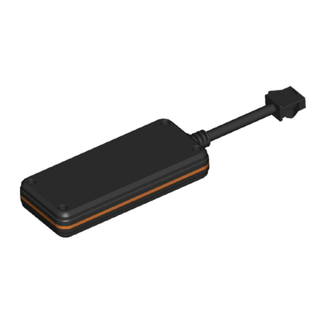
Figure 1-1 illustrates the Tracker in the enclosure. Figure 1-2 illustrates the LED, Reset Button,
Push Button, and Case-Release Hole placements.
a) Top View b) Top Isometric View
c) Bottom View
Figure 1-1: The BLE Asset Tracker Module.
Figure 1-2: The BLE Asset Tracker External Interface Layout.
Reset Button
LoRa Tx/Rx LED
(Red)
Network Join LED
(Green)
Push Button
Push Area
Case-Release
Hole (on side)

BLE Asset Tracker User Guide T0005946_UG Version 1.1
TEKTELIC Communications Inc. Confidential Page 9 of 21
1.2 Specifications and Sensing Functions
The Tracker specifications are listed in Table 1-2.
Table 1-2: BLE Asset Tracker Specifications.
Parameter
Specification
Use Environment
Indoor
Industrial/commercial/residential
Environmental Rating
IP30
Enclosure
Custom design by TEKTELIC
Operating Temperature
5°C ‒45°C
Storage Temperature for Optimal Battery Life
-40° - 85°C
Operating Relative Humidity
5% - 95% (Non condensing)
Storage Relative Humidity
5% - 95% (Non condensing)
Size
63 mm x 26.5 mm x 27 mm
Weight
18 g module; 18 g battery; 36 g total
Power Source
Battery-powered: 1x AA-cell LTC (3.6 V)
Network technology/Frequency band
LoRaWAN in two variants (see Table 1-1):
US915, EU868
Air Interface
LoRa, BLE
Maximum Tx Power
15 dBm
Sensing Elements
BLE scanner, accelerometer, thermometer, battery gauge
Bluetooth Compatibility
BLE based on Bluetooth 5
BLE Sensitivity (0.1% BER)
125 kbps: -103 dBm
500 kbps: -98 dBm
2 Mbps: -91 dBm
Accelerometer Sensitivity
Sample rate: 1 Hz, 10 Hz, 25 Hz, 50 Hz, 100 Hz, 200
Hz, 400 Hz
Measurement range: ±2 g, ±4 g, ±8 g, ±16 g
Precision: 16 mg, 32 mg, 64 mg, 192 mg
Push Button
Configurable operation
Used to force an UL and open a DL window
LED
Green: Joining the network activity
Red: LoRa Tx or Rx activity
Battery Fuel Gauge Features
Measures battery voltage, current, and temperature
EOS alert when the capacity is at 5%
Battery Lifetime
5 years per battery (with nominal use case of 15 BLE scans
and transmissions per day)

BLE Asset Tracker User Guide T0005946_UG Version 1.1
TEKTELIC Communications Inc. Confidential Page 10 of 21
1.2.1 Bluetooth Low-Energy Scanner
The Tracker is equipped with a BLE module that is embedded in the MCU. It serves as a BLE central
device that periodically searches to discover nearby BLE peripherals. It can be used as a
standalone proximity sensor that can also help at positioning.
The BLE scan can be disabled entirely or enabled at any time. Figure 1-3 shows the BLE scan
scheme when the BLE scan is enabled. As shown in the figure, BLE scans are performed
periodically. Each scan duration is divided into scan intervals. The BLE scan is performed only in
the scan window portion of the scan interval. The ratio of the scan window to the scan interval
shows the scan duty cycle. In the case of the scan window equalling the scan interval, the scan
duty cycle is 100%. This represents a continuous scan over each scan duration. This will increase
the likelihood of finding more beacons, but at the expense of consuming more power. The scan
period, duration, interval, and window are all configurable (see the TRM document for
configuration details [1]).
Figure 1-3: The BLE Scan Schematic Procedure.
At the end of each scan duration, up to n discovered BLE devices with the strongest RSSIs are
reported over LoRaWAN. The value n is user configurable (see TRM) [1]. If no devices are found,
an empty list is uplinked. Over each scan duration, a BLE device beacon may be observed
(discovered) more than once, in which case the RSSI associated with the BLE device at the end of
the scan duration is the average value over all observed RSSIs.
The Tracker supports BLE of Bluetooth 5.0. The BLE scan is performed in the passive mode only,
i.e. the Tracker listens to surrounding beacons, but does not transmit to them to request
additional information.
NOTE: The BLE scan is exclusive to LoRa radio transmission; i.e. they do not overlap. If any
reporting becomes due at the same time of a BLE scan, the reporting will be done after the BLE
scan is complete.

BLE Asset Tracker User Guide T0005946_UG Version 1.1
TEKTELIC Communications Inc. Confidential Page 11 of 21
1.2.2 Accelerometer Transducer
Acceleration sensing is provided by an integrated 3-axis accelerometer which can be disabled to
conserve battery life. The main role of the accelerometer in the Tracker is to detect motion that can
indicate a change of the Tracker’s status from stillness to mobility, or vice versa. In this role, the
accelerometer generates an acceleration alarm when a motion event is detected that may or may
not be reported OTA (user-configurable).
An acceleration event report is based on exceeding a defined acceleration alarm threshold count
in a defined alarm threshold period. These thresholds can be customized such that there will not
be multiple reports for a single event, depending on the definition of an event in a particular use
case. An alarm event can only be registered after a configurable grace period elapses since the last
registered alarm event. Carefully setting the grace period is important and prevents from repeatedly
registering an accelerometer event.
The accelerometer can also be polled periodically for its output acceleration vector for applications
in which the Tracker orientation is of interest.
1.2.3 Temperature Transducer
The Tracker includes an on-board thermometer that functions with the specifications listed in
Table 1-2 and supports threshold-based transmission. The temperature is measured from the
built-in MCU transducer. When the temperature thresholds are enabled, the Tracker reports the
temperature when it leaves the configured threshold window, and once again when the
temperature re-enters the threshold window. The Threshold mode is compatible with periodic
reporting of the temperature.

BLE Asset Tracker User Guide T0005946_UG Version 1.1
TEKTELIC Communications Inc. Confidential Page 12 of 21
2Installation
2.1 Included Product and Installation Material
The following items are shipped with each Tracker.
•BLE Asset Tracker in an IP30 polycarbonate enclosure with AA-cell LTC battery installed.
•The BLE Asset Tracker Quick Start Guide [2].
2.2 Safety Precautions
The following safety precautions should be observed.
•The Tracker is intended for indoor use only.
•All installation practices must be in accordance with the local and national electrical
codes.
•Replace only with approved batteries (see section 2.6).
•The Tracker contains an LTC AA-cell battery. When used correctly, lithium batteries
provide a safe and dependable source of power. However, if they are misused or abused,
leakage, venting, explosion, and/or fire can occur. The following are recommended safety
precautions for battery usage [3].
•Keep batteries out of the reach of children.
•Do not allow children to replace batteries
without adult supervision.
•Do not insert batteries in reverse.
•Do not short-circuit batteries.
•Do not charge batteries.
•Do not force discharge batteries.
•Do not mix batteries.
•Do not leave discharged batteries in
equipment.
•Do not overheat batteries.
•Do not weld or solder directly to batteries.
•Do not open batteries.
•Do not deform batteries.
•Do not dispose of batteries in fire.
•Do not expose contents to water.
•Do not encapsulate and/or modify batteries.
•Store unused batteries in their original packaging away
from metal objects.
•Do not mix or jumble batteries.
2.3 Unpacking and Inspection
The following should be considered during the unpacking of a new Tracker.
1. Inspect the shipping carton and report any significant damage to TEKTELIC.
2. Unpacking should be conducted in a clean and dry location.
3. Do not discard the shipping box or inserts as they will be required if a unit is returned for
repair or re-configuration.

BLE Asset Tracker User Guide T0005946_UG Version 1.1
TEKTELIC Communications Inc. Confidential Page 13 of 21
2.4 Commissioning and Activation
The Tracker is shipped in a secured enclosure with the battery preinstalled but disengaged by a
pull tab.
The Tracker enclosure does not need to be opened for activation. Assuming that the Tracker has
been commissioned on the NS, pull out the battery tab to engage the battery. The Tracker will
automatically begin the join process. To turn off the device the battery must be removed. To
reset the device, the external reset button can be pushed; see Section 3.4 for a description of the
reset function.
Refer to Section 3.3 for the expected LED behaviour of the Tracker during the join process. It may
take up to 10 seconds between the time the Tracker was reset and the beginning of the LED join
attempt pattern.
Removing and reinserting the battery will reset the Tracker. As soon as new batteries are
inserted, the Tracker boots up and tries to join a LoRaWAN.
2.5 Mounting
There is a mounting hole on each corner on the bottom side of the Tracker enclosure (see Figure
2-1).
Figure 2-1: The Mounting Hole Locations on the Bottom of the Tracker.
These mounting holes can be used to fasten the enclosure to a solid surface, cable, etc. The
mounting holes are slots so the device can be secured with ropes, zip ties, or hooks depending
on the user’s needs. If using cables or zip ties, they can be threaded through both slots on either
side of the enclosure as shown in Figure 2-2. The recommended zip tie width is 3 mm. Mounting
fasteners are not provided with the Tracker.

BLE Asset Tracker User Guide T0005946_UG Version 1.1
TEKTELIC Communications Inc. Confidential Page 14 of 21
Figure 2-2: Threading Zip Ties Through the Mounting Holes to Fasten the Tracker.
2.6 Battery Replacement
The process for replacing the battery in the Tracker is as follows.
1. Insert the end of a paper clip or similarly thin object into the case-release hole on the right
side of the Tracker. Push the paper clip straight in while simultaneously squeezing the
middles of the sides of the top portion of the enclosure as shown in Figure 2-3. The top
and bottom should unclip from each other and separate.
Figure 2-3: Opening the BLE Tracker Enclosure.
1
2

BLE Asset Tracker User Guide T0005946_UG Version 1.1
TEKTELIC Communications Inc. Confidential Page 15 of 21
Remove the battery and replace with a new one as shown in Figure 2-4. Suggested replacement
batteries are:
•Saft SA LS14500 [4]
•Tadiran SL-360/S [5]
•Tadiran TL-4903/S [6]
•Tadiran TL-5903/S [7]
•Xeno Energy XL-060F STD [8]
Figure 2-4: Replacing the Battery After Opening the Tracker Enclosure.
2. Once the Tracker is powered and tries to join (see Section 3.3 for LED behavior), replace
the bottom enclosure piece by inserting the side with the long snap tab first, as shown in
Figure 2-5. Push the other side of the bottom enclosure piece in until both the top and
bottom fully snap together.
Figure 2-5: Left: Location of the Long Snap Tab. Right: Inserting the Long Snap Tab Side First to
Reattach Enclosure Bottom.
Long snap tab

BLE Asset Tracker User Guide T0005946_UG Version 1.1
TEKTELIC Communications Inc. Confidential Page 16 of 21
3Operation, Alarms, and Management
3.1 Configuration
The Tracker supports a full range of OTA configuration options. Specific technical details are
available in the Tracker TRM [1]. All configuration commands need to be sent OTA during a
Tracker’s DL windows.
3.2 Default Configuration
By default, the Tracker is configured to:
•Report the battery voltage once per day,
•Report an empty UL when the push button is pressed 3 times in less than 3 seconds,
•Report the acceleration vector every time motion is detected, and
•Scan and report up to 4 discovered BLE devices with the largest RSSIs once every hour.
3.3 LED Behaviour
See Figure 1-2 for the location and identification of the Tracker LEDs. The boot and join LED
procedure is as follows.
1. Both LEDs will come on briefly when power is first applied.
2. After a small delay ( < 1 s) the LEDs will turn off and one of them will blink briefly.
a. If the green system LED blinks, then all health checks on the board passed.
b. If the red LoRa LED blinks, then one of the health checks failed. Consider replacing
the battery, or moving the sensor to an environment within temperature range.
3. Immediately after the boot pattern, the join procedure will begin. During this time the
green system LED will blink continuously until the sensor has joined a network.
4. The red LoRa LED will now blink whenever LoRa activity occurs on the sensor (transmitting
or receiving packets, including the join request packets).
During normal operation,
•The red LoRa LED will blink whenever LoRa activity occurs on the sensor (transmitting or
receiving packets), and

BLE Asset Tracker User Guide T0005946_UG Version 1.1
TEKTELIC Communications Inc. Confidential Page 17 of 21
•The green system LED can be controlled via the downlink command interface.
NOTE: Any other LED pattern behaviour not described above most likely indicates a low battery.
For example, if steps 1-2 repeat continuously, the battery no longer has enough charge to power
the join procedure.
3.4 Reset Button Function
There is a reset button on the device, that can be pushed by a pin, such as a paper clip (see Figure
1-2). The button should not be pushed hard. The reset is instant, i.e. the button does not need to
be kept pushed. The reset restarts the microprocessor. All the FW load and configuration
parameters in the Flash are remembered during the reset.
NOTE:Shutting down or resetting the Tracker will cause all unsaved user configurations to be
lost. Save your desired configuration to the Tracker flash before powering off or resetting the
Tracker.
3.5 Push Button Function
The Tracker has an externally accessible push button, actuated by pushing against the enclosure
on a designated area. The main objective of the push button is to trigger the Tracker to send an
uplink such that the Tracker (which acts as a Class-A LoRaWAN sensor) will open receive windows
to receive DL commands.
The definition of when a push button event is registered is user configurable. The default
configuration is pushing and releasing the button at least 3 times within 3 seconds. Alternatively,
the button can be configured to register an event by keeping the button pushed for a defined
number of seconds. In either case, when the event is registered, the Tracker sends an uplink. The
uplink can be empty or configured to contain the battery voltage, acceleration vector,
temperature, BLE scan results, or any combination of these.

BLE Asset Tracker User Guide T0005946_UG Version 1.1
TEKTELIC Communications Inc. Confidential Page 18 of 21
4Compliance Statements
Federal Communications Commission:
This device complies with Part 15 of the FCC Rules [9]. Operation is subject to the following two
conditions:
1. This device may not cause harmful interference, and
2. This device must accept any interference received, including interference that may cause
undesired operation.
To comply with FCC exposure limits for general population / uncontrolled exposure, this device
should be installed at a distance of 20 cm from all persons and must not be co-located or
operating in conjunction with any other transmitter.
Changes or modifications not expressly approved by the party responsible for compliance could
void the user’s authority to operate the equipment. This equipment has been tested and found
to comply with the limits for a Class B digital device, pursuant to Part 15 of the FCC Rules. These
limits are designed to provide reasonable protection against harmful interference in an industrial
installation. This equipment generates uses and can radiate radio frequency energy and, if not
installed and used in accordance with the instructions, may cause harmful interference to radio
communications. However, there is no guarantee that interference will not occur in a particular
installation. If this equipment does cause harmful interference to radio or television reception,
which can be determined by turning the equipment off and on, the user is encouraged to try to
correct the interference by one of the following measures:
•Reorient or relocate the receiving antenna.
•Increase the separation between the equipment and receiver.
•Connect the equipment into an outlet on a circuit different from that to which the
receiver is connected.
•Consult the dealer or an experienced radio/TV technician for help.
Innovation, Science and Economic Development Canada (Industry Canada):
This device contains licence-exempt transmitter(s)/receiver(s) that comply with Innovation,
Science and Economic Development Canada’s licence-exempt RSS(s) [10]. Operation is subject to
the following two conditions:
(1) This device may not cause interference, and

BLE Asset Tracker User Guide T0005946_UG Version 1.1
TEKTELIC Communications Inc. Confidential Page 19 of 21
(2) This device must accept any interference, including interference that may cause
undesired operation of the device.
This device should be installed and operated with minimum distance 0.2 m from human body.
L’émetteur/récepteur exempt de licence contenu dans le présent appareil est conforme aux CNR
d’Innovation, Sciences et Développement économique Canada applicables aux appareils radio exempts de
licence. L’exploitation est autorisée aux deux conditions suivantes:
(1) L’appareil ne doit pas produire de brouillage.
(2) L’appareil doit accepter tout brouillage radioélectrique subi, même si le brouillage est susceptible
d’en compromettre le fonctionnement.
Cet appareil doit être installé et utilise à une distance minimale de 0.2 m du corps humain.
California Proposition 65:
WARNING: This product can expose you to chemicals including lead, nickel, and carbon
black, which are known to the State of California to cause cancer, birth defects or other
reproductive harm. For more information, go to www.P65Warnings.ca.gov [11].

BLE Asset Tracker User Guide T0005946_UG Version 1.1
TEKTELIC Communications Inc. Confidential Page 20 of 21
References
[1]
TEKTELIC Communications Inc., "BLE Asset Tracker: Technical Reference Manual
T0005946_TRM_v0.4," TEKTELIC Communications Inc., Calgary, 2019.
[2]
TEKTELIC Communications, Inc., BLE ASSET Tracker Quick Start Guide
T0005946_QSG_ver1.0, Calgary, 2020.
[3]
Tadiran Batteries GmbH, "Tadiran Lithium Batteries: Technical Brochure LTC-Batteries,"
Tadiran Batteries, Büdingen, Germany, 2020.
[4]
Saft, Specialty Battery Group, "Primary lithium battery: LS 14500," Saft, September 2009.
[Online]. Available: https://datasheet.octopart.com/LS14500-Saft-datasheet-
15505441.pdf. [Accessed 3 March 2020].
[5]
Tadiran Batteries GmbH, "LTC Batteries: SL-360," January 2012. [Online]. Available:
https://datasheet.octopart.com/SL-360-S-Tadiran-datasheet-128477996.pdf. [Accessed
21 February 2020].
[6]
Tadiran Batteries, "Model TL-4903 Technical Data," January 2007. [Online]. Available:
https://datasheet.octopart.com/TL-4903/S-Tadiran-datasheet-556727.pdf. [Accessed 3
March 2020].
[7]
Tadiran Battery Group, "Model TL-5903 Technical Data," November 2011. [Online].
Available: https://datasheet.octopart.com/TL-5903/S-Tadiran-datasheet-8817806.pdf.
[Accessed 3 March 2020].
[8]
Xeno Energy Co. Ltd., "XL-060F Specifications," 2010. [Online]. Available:
http://www.xenoenergy.com/eng/file/Xeno%20Catalog%20XL-060F_E.pdf. [Accessed 3
March 2020].
[9]
Office of the Federal Register, "Electronic Code of Federal Regulations: Title 47; Part 15 -
Radio Frequency Devices," e-CFR, 28 February 2020. [Online]. Available:
https://www.ecfr.gov/cgi-bin/text-idx?SID=86ed79fc9447ceff
183191690a733ec7&mc=true&node=pt47.1.15&rgn=div5#se47.1.15_11. [Accessed 3
March 2020].
[10]
Innovation, Science and Economic Development Canada, "RSS-Gen: General
Requirements for Compliance of Radio Apparatus; Issue 5; Amendment 1," March 2019.
This manual suits for next models
2
Table of contents
Other TEKTELIC Communications GPS manuals
