*
TYPE
50
INTRODUCTION
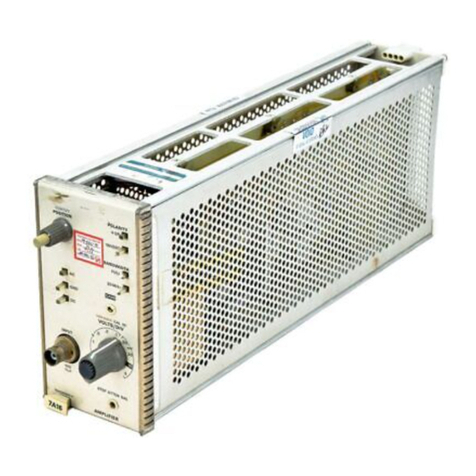
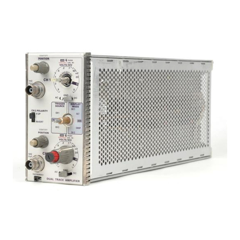
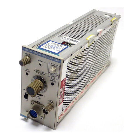
The Tektronix Type 50 Amplifier, Fig.
1,
is designed for
use with Tektronix Type 560-Series Oscilloscopes. It has a
nominal sensitivity of one millivolt per division -that is,
one millivolt of signal at the INPUT connector will produce
a deflection of one graticule division at the oscilloscope
screen. The sensitivity is adjustable, by means of a front-
panel screwdriver adjustment, between about 0.5 and 1.5
millivolts per division. The Type 50 has a bandpass of
15cps to 200 kc and an input resistance of one megohm.
The Type 50 Amplifier is intended primarily to be used
with the Type 51 Sweep module in the Type 560 or Type
AMPLIFIER
561 Oscilloscope for displaying signals produced by
magnetic-ink characters as they are scanned by a magnetic-
ink tester, such as the Kidder Whirly-Sig. A special manual
has been prepared containing instructions for the operation
of these oscilloscopes (with the Type 50 and Type 51
modules) specifically in this application. If you are using
your Type 50 module for this purpose and do not have
the special manual, contact your Tektronix Field Engineer.
This manual describes operating instructions for general
use of the Type 50 module. It also contains a detailed circuit
description of the module, and troubleshooting instructions.
A parts list and schematic diagram are contained at the
rear.
Operating Instructions
Throughout the instructions that follow, it
is
assumed,
unless otherwise stated, that the Type 50 module is inserted
in the Y-axis opening of a Type 560-Series Oscilloscope,
thereby providing vertical deflection of the trace. If the
module is inserted in the X-axis opening it will provide
horizontal deflection, and the instructions must be inter-
preted accordingly. It is further assumed throughout the
discussion that there is a time-base or sweep module in the
X-axis opening of the oscilloscope.
Signal Connections
The signal to be displayed is applied to the INPUT con-
nector on the front panel of the module. For best results,
the signal should be applied through a shielded cable, with
the shield connected to the chassis of both the oscilloscope
and the signal source. Leads should be kept as short as
possible.
High-impedance attenuator probes are available for
applying the signal to the module. These probes reduce
the resistive and capacitive loading effect of the module
and, at the same time, attenuate the signal to allow display
of larger signals than would otherwise be possible. These
probes and other accessories are described in the Acces-
sories section of the oscilloscope manual.
Displaying a Signal
To display a signal with the Type 50 module, proceed
as follows:
1.
Apply the signal (preferably through a shielded cable
or an attenuator probe) to the INPUT connector.
2. Adjust the time-base or sweep controls to obtain a
stable display of the signal.
3.
Set the POSITION control on the Type 50 module so
that the waveform
is
placed as desired on the graticule.
CALIBRATIONAdjustment
The sensitivity of the Type 50 module is adjusted by
means of the front-panel CALIBRATION adjustment. The
setting of this adjustment should be checked and adjusted,
as necessary, whenever the module is moved from one
oscilloscope opening to the other, due to differences in
cathode-ray tube deflection plate sensitivities. It may also
need to be adjusted when you change the module in 'the
other channel because differences in average output volt-
ages between modules can affect the sensitivity of the crt.
The nominal sensitivity of the Type 50 module is 1 milli-
volt per division. To set the CALIBRATION adjustment for
this sensitivity, proceed as follows:
1. If you are using a Type 560 or Type 565 Oscilloscope,
apply 1 millivolt of Calibrator signal through a shielded
cable to the INPUT connector. If you are using a Type
561
Fig. 2. Five-millivolt Calibrator signal displayed with Type 50
CALIBRATION control set for
1
millivolt per division.

