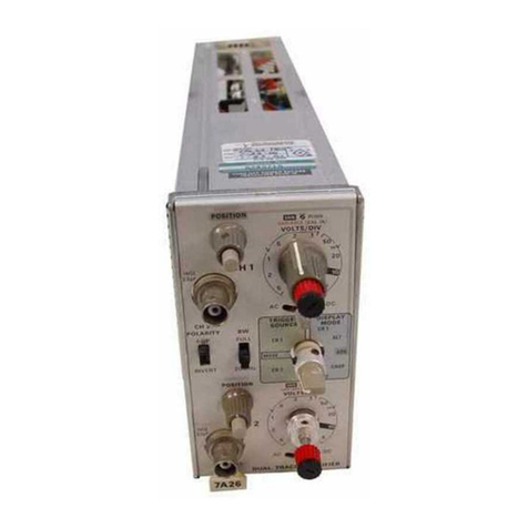
Remove C2721 and R272K
Remove Cl 721. a5-25pF variable capacitor, and R1721. a25n.
0.25W resistor, located near U1750,
Unsolder and lift the ends of R1720 and R1723 (both 1.37kn
resistors) which connect to pin 2and 3. respectively, of U1750.
Trim the leads of the four 15n resistors. Included In the kit. to about
3/16 (0. 1875) Inch.
Add R1722 and R1724. two of the 15n resistors. In series between
the lifted ends of R1720/R1723 and the circuit board pads from which
the ends were lifted.
Add Cl 721. one of the 5-25pF variable capacitors included In the kit.
between the junctions of R1720/R1722 and R1723/R1724.
Unsolder and lift the ends of R2720 and R2723 (both l,3kn) nearest
U2750.
Add R2722 and R2724. the two remaining 15n resistors. In series
between the lifted ends of R2720 and R2723 and the circuit board
pads from which the resistors were lifted.
Add C2721. the remaining 5-25pF variable capacitor, between the
junctions of R2720/R2722 and R2723/R2724.
Replace the faulty amplifier microcircuit (U1350. U1450. U1550,
U1750. U2350. U2450. U2550 or U2750) with the microcircuit
provided In the kit.
Refer to the Calibration Section (5) In the 7A26 Instruction Manual
and check instrument performance. making any necessary
adjustments. The attached manual Insert contains supplemental
calibration Information.
NOTE
In order to optimize the lOOHz to lOOkHz
square wave response (low-frequency
compensation) .several components may need
to be selected. If U1350. U1450 or U1550
has been replaced. C1332. R1332. C1431.
R1341 or Cl 436 may need to be selected.
Replacement of U2350. U2450 or U2550 may
require selection of C2332. R2332. C2431.
R2431 or C2436. In some cases, removal of
C2533 may be desirable.
040-0785-01 page 6
