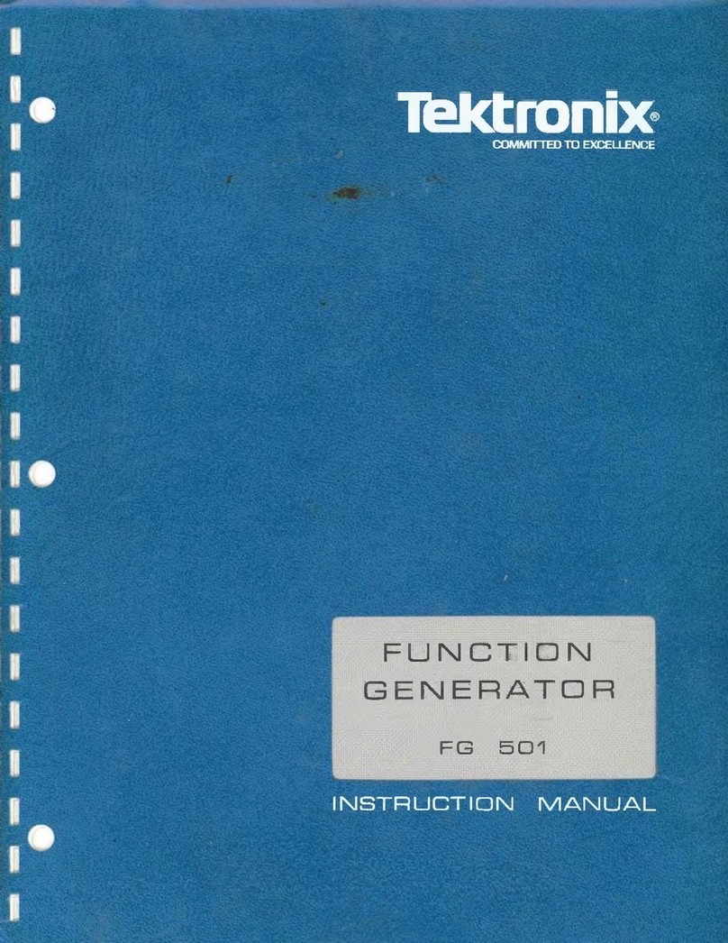
Operating Instructions-FG
501
OPERATING CONSIDERATIONS
NOTE
Before using the
FG
501
for the first time, read the
Operating Considerations in this section and the
description of the front-panel controls, connectors,
and indicators in Fig.
1-3.
Output Connections
The output of the FG 501 is designed to operate as a
voltage source inseries with 50
f2
andworking intoa 50
f2
load. At the higher frequencies, an unterminated or
improperly terminated output will cause excessive
aberrations on the output waveform (see lmpedance
Matching discussion).Loadslessthan50Rwill reducethe
waveform amplitude.
Excessive distortion or aberrations due to improper
termination is lesslikely tooccur at thelowerfrequencies
(especiallywith sineandtrianglewaveforms). However,to
ensure that waveform purity is preserved, observe the
following precautions:
1. Use quality 50
f2
coaxial cables and connectors.
2.
Makeall connections tight andas short as possible.
3.
Use quality attenuators, if necessary, to reduce
waveform amplitude to sensitive circuits.
4. Useterminators or impedance-matching devicesto
avoid reflections when using long cables, i.e., six feet or
more.
5. Ensure that attenuators, terminations, etc. have
adequate power-handling capabilities for the output
waveform (approximately 0.5 W into a 50
f2
load).
Power output isdetermined bytheselected waveform,
itsamplitude, and the amount of offset voltage selected.
Thephysical and electricalcharacteristicsof thepulse-
transmitting cable determine the characteristic im-
pedance, velocity of propagation, and amount of signal
loss. Signal loss, due to energy dissipation in the cable
dielectric, is proportional to the frequency; therefore, a
few feet of cable can attenuate high-frequency informa-
tioninafast-rise pulse.Itisimportanttokeepthesecables
as short as possible.
When signal comparison measurements or time
difference determinations are made, the twosiignalsfrom
the test device should travel through coaxial cables with
identical loss and time-delay characteristics.
Ifthereisadcvoltage acrosstheoutput load,theoutput
pulse amplitude will be compressed; or insorne cases, if
the voltage exceeds
f
10
V,
it may short the output. To
prevent this from occurring, the output must be coupled
through a dc blocking capacitor to the load. The time
constant of the coupling capacitor and load must belong
enough to maintain pulse flatness.
Risetime and Falltime
If the output pulse from the FG 501 is used for
measuring the rise or falltime of a device, the risetime
characteristics of associated equipment may have to be
considered. If the risetime of the device under test is at
least 10times greater than the combined risetimesof the
FG 501 plus the monitoring oscilloscope and associated
cables, the error introduced will not exceed 1% and
generally can be ignored. If the rise or falltime of the test
device, however, is less than 10 times as long as the
combined risetimes of the testing system, the actual
/-
risetimeof the device will havetobedeterminedfromthe
risetime of each component making up the system. This
equals the square root of the sum of the squares of the
individual risetimes. Conversely,therisetimeof thedevice
under test can be found from the same relationship if all
theactual risetimes inthesystemareknownexceptthatof
the device under test.
lmpedance Matching
Reflections.
As a pulse travels down a transmission
line, eachtime itencountersamismatch,or animpedance
different than the transmission line, a reflection is
generated and sent back alongthe linetothe source. The
amplitude and polarity of the reflections are determined
by the amount of the encountered impedance inrelation
to the characteristic impedance of the cable. If the
mismatch impedance is higherthantheline,thereflection
will be of the same polarity as the applied signal; if it is
lower, the reflection will be of opposite polarity. If the
reflectedsignal returns beforethe pulseisended, itadds
to or subtracts from the amplitude of the pulse. This
distorts the pulse shape and amplitude.
MatchingNetworks.
Thefollowingdescribes methods
for matching impedance networks into relatively low
impedances. If the FG 501 is driving a high impedance,
--
such as the
1
MR inputimpedanceof the vertical inputfor
an oscilloscope,thetransmission linemust beterminated
REV.
B
JUL
1978
