manuals.online logo
Brands
  1. Home
  2. •
  3. Brands
  4. •
  5. Tektronix
  6. •
  7. Portable Generator
  8. •
  9. Tektronix FG501 User manual

Tektronix FG501 User manual

......

......

.....

.... ... .. .. .
........
070-1431-01
Te
k
tro
nb
c
CO
M
M
ITT
E
D
TO
E
XC
E
LLE
N
C
E
FUNCTION
GENERATOR
1
INSTRUCTION
M
ANUAL
Te
k
tro
n
i
x
,
Inc
.
Ρ
.
Ο
.
Box
500
B
eaverto
n
,
Orego
n
97077

Serial
N
u
m
ber
F
irst
p
ri
n
ti
ng
A
ug
u
st
Ι
972
nearest
Tektron
timber
r
is
warranted
against
detecfit
"c
meAc'
-
iw
.i
and
rmal
use,
for a
nix
will
repair
or replace,
at
its
op
termined
to
be
defecUve
within
the
wana
ix
Servicx?
!^
ι
;υ
,
vvorkt
iniflal
shipment,
produccis
de
avd
rv-
?
urnpd,
freight
prepaid
.,
to
fitness
wof
I
01i
Y

V%

k1i
Please
direct
all
requests
for
service
or
replacement
parts
to
the
nter or Field
Office,
include
the
type
or
product
and
its
serial
number
.
Copyright
-)
197
2
,
1978 by
Tektronix
.
reserved
.
Contents
of this
publication
may
not
be
duced
in
any
form
without
the
permissio
ektronix,
I
Products
of
Tektronix,
inc
.
and
its
subsidiaries
ar
;
a
covered
by
U
.S
.
and
foreign
patents
and/or
pending
patents
.
TEKTRONIX,
TEK,
SCOPE-MOBILE,
TELEQWPMENT,
and

are
registered
trademarks
of
Tektronix,
Inc
.
Printed
in
U
.S
.A
.
Specification
and
price
change
privNeges
are
reserved
.
TABLE
Ο
F
CO
N
T
EN
TS
S
E
CTIO
N
1
S
E
CTIO
N 2
W
A
RN
ING
,
THE
FO
LL
O
W
I
NG S
ERV
ICI
N
G
I
N
ST
RU
CTIO
N
S
AR
EF
OR
U
SE
BY
Q
U
A
L
I
F
I
E
D
PER-
SO
NNEL
O
NL
Y
.
T
O
AV
OID
PER
SO
N
A
L
I
NJUR
Y,
DO
NOT
PERFO
RM
ANY
S
ERV
ICI
N
G
OT
HER
THAN THAT
CO
N
TAI
NE
D
IN
OPER
ATI
NG
I
N
ST
RU
CTIO
N
S
UNLE
SS
YO
U
A
RE
QUA
L
I
F
I
ED
TO
DO
SO
.
C
HA
N
G
E
I
NF
O
RM
ATIO
N
SE
CTIO
N
3
AD
JUST
MEN
T
3-1
SE
CTIO
N
4
M
AI
NT
EN
A
N
C
E
AND
I
NT
ERF
ACI
NG
I
NF
O
RM
ATION
4-1
SE
CTIO
N
5
CI
R
CU
IT
D
E
SC
R
I
P
TIO
N
5-1
SE
CTIO
N
6
O
P
TIO
N
S
6-1
SE
CTIO
N
7
REPL
AC
E
A
BLE ELE
CT
R
ICA
L P
A
R
TS
7-1
S
E
CTIO
N 8
DIAG
RA
M
A
ND
CI
R
CU
IT
B
OA
RD
I
LLU
ST
R
ATIO
N
8-1
SE
CTIO
N9
REPL
AC
E
A
BLE
ME
CHAN
ICA
L P
A
R
TS
A
N
D
E
X
PL
OD
E
D
V
IE
W
9-1
,.
P
age
O
PER
ATI
N
G
I
N
ST
RU
CTIO
N
S
1-1
S
PE
CI
F
ICATIO
N
AND
PERF
O
RM
ANC
E
C
HE
C
K
2-1
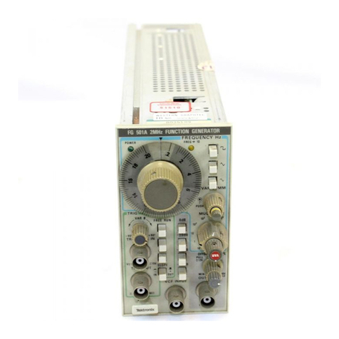
Fig
.
1-1
.
FG
501 Function
Generator
I
N
T
R
OD
U
CTIO
N
Th
e F
G
501 Function
Generator
is
designed
to
op
erate
i
nα
TM
500-Series
p
ower
mo
d
ule
.
L
ow
d
istortion
si
n
e,
s
q
uare,
triangle,
pulse,
an
d
ramp
waveformsfrom
0
.001
Hz
to
1
MH
z as
well
as
α
+2,5
volt
sq
uare-wave
trigger
are
available
at
t
he
front
p
an
el
.
V
ariable
DC
offset
of
±7
.5
volts
is
also
p
rovide
d
.
Α
"h
ol
d
"
feature
allows
t
he
ge
n
erator
outp
ut to
be
abru
p
tly
h
alted
at
its
instantaneous
voltage
level
an
d
h
el
d
t
here un
til
ma
n
ually
switc
h
ed on
again
.
Α
voltage-controlle
d
fre
q
uency
(V
C
F) in
p
ut is
provi
d
ed
to
control
t
h
e
out
p
ut
fre
quency
from
an
exter
n
al
voltage
source
.
T
he outp
ut
fre
quency
can
be
swe
p
t
above
or
below
t
h
e
selecte
d
fre
q
ue
ncy
to
α
maxim
u
m
of
1000
:1
de
pe
nd
ing
on
t
he
polarity
and
am
p
litu
d
e
of
t
he
V
C
F
i
n
put
an
d
t
h
e
selecte
d
output
frequency
.
Also
inclu
d
ed
is
an
exter
n
al
gate
in
p
ut
t
h
at
allows
t
he
generator
to
be
tur
n
ed on
for
t
h
e
d
uration
of
an
externally
ap
p
lie
d
gating
signal
.
T
h
is
mo
d
e
p
rovi
des
eit
h
er
α
single
cycle
outp
ut
or
α
train
(burst)
of
p
reselected
waveforms
dependi
n
g
on
t
he
gating
sig
n
al
width an
d
t
he
ge
n
erator
fre
q
uency
setti
n
g
.
T
he
p
h
ase
(start level)
of
t
he
waveform
burst
can be
varie
d
±90°
b
yα
fro
n
t-
p
an
el
con
trol
.
T
he
variety
of
swe
p
t
a
n
d
mo
d
ulate
d
signals
available
from
t
he
F
G
501
ma
ke
it
es
p
ecially
usef
u
l
for
suc
h
ap
p
lications
as
testing
servo-system
or
amplifier
res
p
onse,
distortio
n
,
and
stability
;
FM
ge
n
eratio
n
an
d
fre
q
uency
multiplicatio
n
;
or
sim
p
ly
u
sed
as
α
variable
beat-fre
q
ue
ncy
oscillator,
re
p
etitio
n
-rate,
o
r
tone-burst
ge
n
erator
.
T
h
e
sq
uare-wave
trigger
outp
ut
ca
n
be
use
d
as
α
source
for
tra
n
sistor-tra
n
sistor
logic
(TT
L
)
or
to
syn-
ch
ro
n
ize
an
exter
n
al
device such as
an
oscilloscope
or
counter
.
T
h
e
F
G
501
is
calibrated
a
nd
ready
for
use
w
h
en
received
.
It
is
design
ed
to
op
erate
in
any
compartment
of
α
TM
500-Series
power
module
only
.
R
efer to
t
he
p
ower
mo
d
ule
I
n
st
r
uctio
n
Manual
for
line
voltage
re
q
ui
r
eme
n
ts
a
nd
power
mo
d
ule
operatio
n
.
REV
.
C
JUL
197
8
OPERATING
I
N
ST
RU
CTIO
N
S
Installation
an
dR
emoval
Sectio
n
1-
F
G
501
Turn
t
he
p
ower
mo
d
ule
off
before
inserting
t
h
e
plug-
in
;
otherwise,
d
amage
may
occu
r
to
t
h
e
plug-in
c
ί
rcuitry
.
B
ecause
of
t
h
ehigh cu
r
rent
drawn
by
t
he
FG
501,
it
is
also
r
ecommen
d
e
d
th
at
t
he
p
owe
r
mo
d
ule
be turned
off
before
removing
t
h
e
FG
501
.
R
efer
to
Fig
.
1-2
.
C
h
ec
k
to
see
th
at
t
he
plastic
barriers
on
t
h
e
interconnecting
jac
k
of
t
h
e
selecte
d
p
ower
module
compa
r
tment
matc
h
th
e
cut-outs
in
t
he
F
G
501
circuit
board
edge
connector
.
Align
t
h
e F
G
501
ch
assis
wit
h
t
he
upper
a
nd
lower
guides
of
t
h
e
selected
com
p
artme
n
t
.
P
ush
t
h
e
mo
d
ule
in
a
nd
p
ress firmly
to
seat
t
he
circuit
board
in
t
he
inter-
connecting
j
ac
k
.
Pull
t
he
P
ower
switc
h
on
t
h
e
fro
n
t
p
anel
of
t
he
p
ower
module
to
apply
p
ower
to
t
h
e F
G
501
.
Observe
t
h
at
t
h
e
P
O
WER
indicator
lig
h
t
on
t
he F
G
501
comes
on
.
R
emove
t
he F
G
501
from
t
he
power
mo
d
ule
by p
ulli
ng
t
he
release
latc
h
at
t
he
bottom
of
t
he
fro
n
t
pa
n
el
a
nd
sliding
t
he
unit
straig
h
t
out
of
t
he p
ower
module
.
F
ig
.
1-2
.
P
l
u
g-i
n
i
n
stallatio
na
nd
r
emoval
.
O
p
e
r
ating
I
n
st
ru
ctions-
F
G
501
O
PER
ATI
N
G
CON
SID
ER
ATIO
N
S
ΝΟΤΕ
Befo
r
e
using
t
h
e
FG
501
fo
r
t
h
e
first
time,
r
ead
t
he
Operati
n
g
Co
n
siderations
in
t
h
is
section
an
d
t
he
d
esc
r
i
p
tion
of
t
he
f
r
ont-panel
controls,
connectors,
and
indicators
i
n
F
ig
.
1-3
.
Out
p
ut
Con
n
ections
T
he
output
of
t
he
F
G
501
is
designed
to
operate
as α
voltage
source
in
series
wit
h
50
Ω
and
wor
k
i
ng
i
n
to
α50
Ω
load
.
At
t
h
e
h
ig
h
er
f
r
e
qu
encies,
an un
te
r
mi n
ated
or
im
p
roperly
termi
n
ated
output
will
ca
u
se
excessive
a
b
erratio
n
s
on
t
he outp
ut
waveform
(see
Impe
d
ance
M
atc
hing
disc
u
ssion)
.
L
oa
d
s
less
than 50
Ω
will
re
d
ucet
he
waveform
am
p
litude
.
E
xcessive
distortion or
a
b
errations
due
to
imp
r
op
er
terminatio
n
is
less
li
k
ely
to
occur
at
t
he
lower
fre
q
ue
n
cies
(especially
wit
h
sine
an
d
tria
n
gle
waveforms)
.
H
oweve
r
,
to
en
sure
t
h
at
waveform pu
r
ity
is
preserve
d
,
observe
t
he
following precautio
ns
:
1
.
U
se q
uality
50
Ω
coaxial
cables and
con
n
ectors
.
2
.

M
a
k
e
all
con
n
ectio
n
s
tig
h
t
a
nd as s
h
ort
as
p
ossible
.
3
.
Use q
uality
atte
nu
ators,
if
necessa
r
y,
to
red
u
ce
waveform
am
p
litude
to
sensitive
ci
r
cuits
.
4
.
U
se
termi
n
ators
or
im
p
edance-matc
h
i
n
g
devices
to
avoid
reflectio
n
s
w
h
e
n
usi
ng long ca
b
les,
i
.e
.,
six
feet or
more
.
5
.
E
nsure
t
h
at
atte
n
uators,
termi
n
ations,
etc
.
h
ave
ad
e
qu
ate
power-
h
andli
ng capa
b
ilities
for
t
he output
waveform
(a
pp
roximately
0
.5
W
into
α
50
Ω
load)
.
P
ower
o
u
tput
is
determine
d
by
t
he
selecte
d
waveform,
its
am
p
litude,
a
nd
t
h
e
amou
n
t
of
offset
voltage
selected
.
T
he p h
ysical
a
nd
electrical
ch
aracteristics
of
t
he pu
lse-
tra
n
smitti
n
g
cable d
etermi
ne
t
h
e ch
aracteristic
im-
pedance,
velocity of
prop
agatio
n
,
and
amou
n
t
of
sig
n
al
loss
.
Signal
loss,
d
ue
to
en
ergy
d
issipatio
n
i
nth
e
ca
b
le
dielectric,
is
p
ro
p
o
r
tio
n
al
to
t
h
e
fre
q
ue
n
cy
;
t
h
erefore,
α
few
feet
of
ca
b
le
can
atte
n
uate
h
ig
h
-freque
ncy
i
n
forma-
tio
n
in
α
fEkst-rise
p
ulse
.
It
is
importantto
k
eept
h
ese
cables
as sh
ort
as
possible
.
Wh
en
signal
com
p
arison
measurements
or time
difference
determinatio
ns
are
made,
t
h
e
two
signals
from
t
he
test
device
s
h
o
u
ld
travel
t
h
roug
h
coaxial
cables
wit
h
identical
loss
and
time-d
elay
c
h
aracteristics
.
If
t
here
is
α
d
o
voltageacross
t
h
eoutput
load,
t
h
e
output
p
ulse
am
p
litu
d
e
will
be
compressed
;
or
in
some
cases,
if
t
he
voltage
excee
d
s
±10
V,
it
may
sh
ort
t
heoutput
.
To
preven
t t
h
is
from
occurring,
t
h
e
output
must
b
e
coupled
t
h
roug
hα
do
b
loc
king cap
acitor to
t
h
e
loa
d
.
The
time
con
sta
n
t
of
t
he
cou
p
li
n
g
ca
p
acitor
an
d
loa
d
must be
lo
n
g
eno
ug h
to
maintai
n
p
ulse
flat
ness
.
R
isetime
and
Falltime
If
t
h
e
out
p
ut
pulse
from
t
h
e
F
G
501
is
use
d
for
measuri
ng
t
he
r
ise
or
falltime
of
α
d
evice,
t
h
e
risetime
ch
aracteristics
of
associate
d
eq
ui
p
me
n
t
may
h
ave
to
be
considered
.
If
t
he
risetime
of
t
he device un
der
test
is
at
least
10 times
greater
t
han
t
he
combine
d
risetimes
of
t
he
F
G
501
plus
t
he monitoring
oscilloscope
a
nd
associate
d
cables,
t
h
e
error
i
n
troduced
will
n
ot
exceed
1
ο/ο
an
d
generally
can
be ignored
.
If
t
he
rise
or
falltime
of
t
he
test
device,
h
owever,
is
less
t
han 10 times as long as
t
he
combi
ned
risetimes
of
t
h
e
testi
ng
system,
t
h
e
actual
risetime
of
t
he device
will
h
ave
to
b
e
d
eterminedfrom
t
h
e
risetime
of
eac
h compone
n
t
ma
k
i
ng up
t
h
e
system
.
T
h
is
equals
t
he s
q
uare
root
of
t
he
sum
of
t
he sq
uares
of
t
h
e
i
n
divi
d
ual
risetimes
.
Co
n
versely,t
herisetimeoft
h
edevice
under
test
can
be
found
from
t
h
e
same
relations
h
ip
if
all
t
he
actual risetimes
in
t
h
e
system
are
kn
own
except
t
h
at
of
t
he device
under
test
.
Im
p
edance
M
atc
h
i
ng
R
eflectio
n
s
.
As
α
pu
lse
travels
d
own
α
tra
nsmission
line,
eac
h
time
it
encou
n
ters
α
mismatc
h
,
or
an im p
eda
n
ce
differe
n
t t
han
t
he transmission
li
n
e,
α
r
eflection
is
generate
da
nd
sent
backalon
g
t
he
line
to
t
he
source
.
T
he
amplitude
and
p
olarity
of
t
he
reflectio
ns are
d
etermi
n
ed
b
y
t
he
amount
of
t
h
e
encountere
d
impedance
i
n
relatio
n
to
t
he ch
aracteristic
im
p
edance
of
t
he ca
b
le
.
If
t
he
mismatc
h im
p
edance
is
h
ig
h
er
t
han
t
h
e
line,
t
h
e
reflectio
n
will
be
of
t
h
e
same
p
olarity
as
t
h
e
applied
sig
n
al
;
if
it
is
lower,
t
h
e
reflection
will
b
e
of
o
p
posite
p
ola
r
ity
.
If
t
h
e
reflecte
d
signal
retur
ns before
t
h
e
pulse
is
en
d
ed,
it
ad
ds
to or
subtracts
from
t
h
e
am
p
lit
u
de
of
t
hepulse
.
Th
is
distorts
t
he p
ulse
s
h
ape
a
nd
amplitude
.
M
atc
h
ing
N
etwor
ks
.
T
he
following
d
escribes
met
h
ods
for
matc
h
ing
impedance
networ
k
s
i
n
to
relatively
low
impedances
.
If
t
h
e
F
G
501
is
d
rivi
ng α
h
ig
h
impe
d
ance,
suc
h as
t
he
1
ΜΩ
i
np
ut
impedance
of
t
h
e
vertical
inpu
t
for
an
oscilloscope,
t
h
e
transmissio
n
line
must be
termi
n
ate
d
REV
.
Β
JUL
197
8
Selects
sine,
triangle,
square,
ramp,
and
pulse
output
waveforms
.
Pulse
and
ramp
waveform
duration
is
1/2f
.
See
Operating
Con-
siderations
for
addi-
tional
information
.
Concentric
with
OFF-
SET
control
.
Varies
am-
plitude
of
waveform
at
the
OUTPUT
connector
from
less
than
500
mV
(fully
ccw)
to
20 V
p-p
open
circuit
(
S N
B130000-up)
.
For
SN
below
8130000,
con-
trol
is
label
OUTPUT
and
provides
a
maximum
of
15
V
p-p
open
circuit
.
REV
C,
MAR
197
9
FUNCTION
Selector
AMPL
Control
OFFSET
Control
Concentric
with
AMPL
contrN
.
For
S
N
13130000-up,
control
pullout
provides a
var-
able
dc
offset
voltage
from
zero
(centered)
to
either
--
7
.5
V
(fully
cew)
or

+7
.5
V
(fully
cw)
.
When
pushed
in
pro-
vides
zero
off-set,
For S
N
below
B130000
control
does
not
pull
out
and
offset
limits
are
-
5
V
to
+5 V
.
PHASE
Control
When
pulled
out provides
continuously
variable
selection
of the
gated
output
waveform
start
level
(phase)
from
+90
0
(fully
ccw)
to
-90
0
(fully
cw)
referenced
to
the
sine
or
triangle
waveform
0
0
starting
point
.
Used
in
conjunction
with
the
GATE
INPUT
connector
when
operating
in
gated
output
(burst)
mode
.
TRIG
OUTPUT
Connector
Bs
m
connector
that
pre
vides
a
+2
.5
V
square-
wave
trigger
output
into
a
600
0
load,
OUTPUT
Connector
Bnc
connector
that
pro-
vides
the output
wave-
form
selected
by the
FUNCTION
selector,
POWER
Indicator
GATE
INPUT
Connector
A
brie
connector
for
applying
a
+2
V
to
+15
V
gating
signal to
the
generator
.
Fig
.
1-3
.
Operating
controls
and
connectors
.
when
power
is
ap-
the
FG
501
.
Operating Instructions-FG
501
FREQUENCY
Hz
Dial
The frequency
of
sine,
triangle
and
square
waveforms
is
the
dial
reading
times
multiplier
.
Ramp
arid
pulse
wave-
forms
have
a
frequency
approximately
1
.6X
dial
setting
times
multiplier
with the
MULTIPLIER
at
1
or
above
and
a
fre-
quency
of
approximately
2X
dial
setting
on
the
three
lowest ranges
of
the
MULTIPLIER
selec-
tor
.
Provides
vernier
selec-
tion of
output
frequency
from
the
fully cow
(calibrated)
position
to
approximately
0
.35%
of
full
scale
in
the
fully
ccw
position
.
MULTIPLIER
Selector
Selects
frequency range
in
9
decade
steps
and
provides
three
"hold"
positions
(between
the
lowest
three
multiplier
positions)
that
hold
the
generator
output
at
any
desired
instantaneous
voltage
level
.
Bnc
connector
for
apply-
ing
an
external
voltage
for
controlling
the
output
frequency
o
f
the
generator
.
A
10
V
input
provides a
frequency
range
of
1000
:
1
.
1431-13A
O
perating
Instructions-FG
501
into
α
50
Ω
attenuator
and
α
50
Ω
termination
at
the
oscilloscope
input
.
The
attenuator
isolates
the
input
capacity
of
the device
.
Distortion
can
be
caused
by
this
input
capacity
.
Α
simple
resistive
impedance-matching
n
etwork
t
hat
p
rovides
minimum
attenuation
is
illustrated
in
F
ig
.
1-4
.
To
match
impedance
with
t
he
illustrated
network,
the
follow-
i
n
g
co
n
ditio
ns
must
exist
:
and
Th
erefore
:
(R,
+
Ζτ
)
R
τ
m
u
st
eq
ual
Ζ
,
R
,+
Ζτ
+
R
z
R,
+

Z,
R
2

must
equal Ζτ
Z,+
R
z
R
ι
R
z
=
ΖιΖ
z
;
and
R
ιΖι
=
R
z
(
Ζτ
-
Ζ
I
)
or
R
ι
=

Ζτ
(
Ζτ
-
Ζι
)
and
R
z
=
Ζι
-
\
Ι

Ζ
2
Ζ
_
τ
Ζ
,
F
or
exam
p
le
;
to
matc
hα50
Ω
system
to
α
125
Ω
system,
Ζ
,
eq
uals
50
Ω
a
n
d
Ζ
2
eq
uals
125
Ω
.
Th
erefore
:
R,=-\/i25-(125-50)
=96
.80
an
dR
2
=
50

125
25
50
-
64
.6
Ω
Wh
en
co
n
structi
n
g
suc
h
α
d
evice,
t
h
e
environme
n
t
surrounding
t
h
e
compo
nents
s
h
ould
also
b
e
design
ed
to
provide α
transition
b
etwee
n
t
he im
p
edan
ces
.
K
eep
in
mind
t
h
at
t
h
e
c
h
a
r
acteristic
im
p
eda
n
ce
of
α
coaxial
d
evice
is
determined
by
t
he
ratio
b
etwee
n
t
h
e
outsi
de diameter
of
t
h
e
in
ne
r
conductor
to
t
h
e
i
n
si
de
d
iameter
of
t
he
outer
cond
uctor
.
τ
ο
=
138/
ε
log,o
D/d,
w
here
D
is
t
h
e
i
n
side
diameter
of
t
h
e outer
con
d
uctor,
a
n
d d
is
t
he outside
diameter
of
t
he
in
ne
r
conductor
.
ε
is
t
h
e
dielectric
co
n
s-
tant
(1 in
air)
.
Attenuation
R
atios
.
Th
o
u
g
h
t
he
networ
k
i
n F
ig
.
1-4
provi
d
es mi
n
imum
atte
n
uatio
n fo
r
αpu
r
ely
resistive
im pe
d
a
n
ce-matc
h
i
n
g
d
evice,
t
h
e
atte
nu
atio
nas seen
from
o
ne
end
does
not eq
ual
t
h
at
see
n
from
t
he
ot
he
r
en
d
.
Α
signal
(
Ε
,)
ap
p
lied
from
t
h
e
lower
impeda
n
ce
sou
r
ce
(
Ζ
,)
en
cou
n
ters
α
voltage
atte
n
uation
(
Αι
)
w
h
ic
h
is
g
r
eater
t
han
1
an
d
less
t
han
2,
as
follows
:
Α
,
=Ez =
Ζτ
+
1
Fig
.
1-4
.
I
mp
edance-match
i
ng
n
etwor
kth
at pr
ovi
d
es
m
i
n
im
um
attenuatio
n
.
Α
sig
n
al
(
Ε
2)
app
lied
from
t
he
h
ig
h
er
im
ped
an
ce
source
(
Ζ
2)
en
cou
n
ters
α
greater
voltage
atten
u
atio
n
(
Α
2)
wh
ic
h
is
greater
t
han
1
a
nd
less
t
h
an
2
(Z2/Z,)
:
_
Ετ
__
R'
+
R'

+
1
Az
=

Ε
ι

Rz

_EL
In
t
h
e
example
of
matc
hing 50
Ω
to
125
Ω
.
Α
'

925
+1=1
.77
Α
2
=
96
.8
+
96
.8
+
1
=
4
.44
64
.6
50
T
he
illustrated
n
etwor
k
can
b
e
mo
d
ified
to
p
rovide
different
attenuatio
n
ratios
by
ad
d
i
ng anot
h
er
resistor
(less
t
han
R,)
betwee
n
Ζ
,
an
d
t
h
e
j
un
ctio
n
of
R,
an
dR
z
.
Duratio
n
of
R
amps
and
P
ulses
Th
ed
uration
of
ramp
an
d
p
u
lse
waveforms
is
always
eq
ual
to
t
he h
alf-cycle
time
of
t
h
e
sine,
square,
or
triangle
waveform
freque
n
cy
.
For
MUL
TI
PL
I
ER
setti
n
gs
of
1
or
greater,
t
he
retrace/off
time
is
suc
h
t
h
at
t
h
e
waveform
h
as
αdu
ty
cycle
of
approximately
80
ο
/
ο, i
.e
.,
fre
quen
cy
equals
a
pp
roximately
1
.6
Χ
FRE
Q
UEN
CY
Hz
dial setti
n
g
.
For
MUL
TI
PL
I
ER
setti
n
gs
less
t
h
an
1,
t
h
e
retrace/off
time
is
from
10
ms
to
100 ms,
w
h
ic
h
results
i
n duty
cycles
a
pproaching
100
ο/ο
;i
.e
.,
frequency
equals
approximately
2
Χ
FRE
Q
UEN
CY
Hz
d
ial
setting
.
REV
.
Β
JUL
197
8
Free-
R
u
nn
ing
O
u
tput
T
he
following
proced
u
re
provi
d
es
α
fr
ee-run
n
ing
waveform
outp
ut
wit
h
variable
fre
q
ue
n
cy
an
d
amplitude
.
1
.
Set
t
h
e
A
MPL
control
to
t
he
fully
co
u
ntercloc
k
wise
p
osition
and
t
he
O
FF
S
E
T
co
n
trol
to
t
he 0 (cen
tered)
positio
n
.
C
h
eck
t
h
at
t
he
PH
AS
E
co
n
tr
ol is
pus
h
ed
in (off)
.
2
.
Set
t
he
FUN
CTIO
N
selector
to
t
h
ed
esired
waveform
(see
F
ig
.
1-5)
.
F
ig
.
1-5
.
O
u
t
p
ut
wavefo
r
ms
availa
b
le
f
r
om
t
he F
G
501
.
3
.
Select
t
he
desire
d
fre
quen
cy
wit
h
t
h
e
MUL
TI
PL
I
ER
selector
a
nd
FRE
Q
UEN
CY
Hz
d
ial
.
F
or
exam
p
le,
if
t
h
e
MUL
TI
PL
I
ER
selecto
r
is
set
to
t
he10
5
p
osition
an
d
t
h
e
FRE
Q
UEN
CY
Hz
d
ial
is
at
5,
out
p
ut
fre
q
ue
ncy
is
500
kH
z
;
i
.e
.,
MUL
TI
PL
I
ER
setting
Χ
FRE
Q
UEN
CY
Hz
setti
ng
.
T
h
e
output
fre
q
ue
n
cy
is
calibrated
w
h
e
n
t
h
e
FRE
Q
UEN
CY
VERN
I
ER
control
is
in
t
h
e
fully
cloc
k
wise
p
ositio
n
.
T
h
e
d
uratio
n
of
ram
p
a
n
dpulse
waveforms
is
depende
n
t
on
t
he
MUL
TI
PL
I
ER
setti
n
g
.
See
Duration
of
R
am
p
s
an
d
P
ulses
under
O
p
erating
Co
n
si
d
eratio
n
s
for
furt
h
er
i
n
formatio
n
.
4
.
Connect
t
h
e
loa
d
to
t
he
O
U
T
PU
T
connecto
r
and
a
dj
ust
t
he
A
MPL
co
n
trol
for
t
h
e
desired outp
ut
am
p
litu
de
.
V
a
r
iable
DC
Offset
Pull
outwar
d
on
t
he
O
FF
S
E
T
con
trol (pull
switc
h
a
dded
at
S
N
13020000)
to
positio
n
t
h
edo
level
(baseli
n
e)
of
t
h
e
outpu
t
waveform
.
F
or
exam
p
le,
+5
V
of offset
will
i
n
c
r
ease
t
he
do
+
p
eak ac voltage
of
α7
.5
Vρ
-
ρ
out
p
ut
to
+5
and
+12
.5
V
do
+
p
ea
k
ac
w
h
ile
-5
V
of offset
will
re
d
uce
t
h
e
d
o
+
pda
k
ac
outp
ut
to
+2
.5
V
a
nd
-5
V
.
REV
.
C
JUL
197
8
O
PER
ATIO
N
Ope
r
ati
n
g
I
n
st
ru
ctio
n
s-
F
G
501
Gate
d
(
B
urst)
Output
an
d
V
ariable
Ph
ase
Α
gating
sig
n
al
of
2
to
15
V
amplitu
d
e a
pp
lie
d
to
t
he
GAT
E
I
NPU
T
connector
wit
h
t
h
e
PHAS
E
control
pu
lled
out
will
provide
α
burst
of
cycles
at
t
he
O
U
T
PU
T
co
nn
ector
.
T
he
d
uration
of
t
h
e
burst
a
nd nu
mber
of
cycles
in
t
h
e
bu
r
st
depen
d
on
t
h
e
gati
ng
signal
du
r
atio
n an
d
t
he
output
fre
q
uen
cy
selecte
d
.
Wh
en
t
h
e
gati
ng
sig
n
al
goes
to
t
h
e
zero
level,
t
he
ge
n
erator
completes
its
last
cycle an d
remains q
uiescent
un
til
t
h
e
n
ext
gating
signal
.
Si
ngle
cycles
can
b
e obtained
by a
p
plyi
ng
α
gati
ng
signal
wit
h
α
perio
d
approximately
equal
to
t
he
p
erio
d
of
t
he
F
G
501 ou
tput
waveform
.
T
he
n
um
b
er of
cycles pe
r
b
urst
can be ap
p
roximated by
d
ivi
d
i
n
g
t
he
gating
sig
n
al
duration
by
t
he p
eriod
of
t
h
e
F
G
501
out
p
ut
f
r
eq
ue
ncy
.
GAT
E
INPU
T
OUT
PU
T
GAT
E
INPU
T
OUTPUT
GAT
E
I
NPU
T
OUTPUT
PH
AS
E
co
n
tr
ol
at
90
°
L
AG
PH
AS
E
co
n
trol
at
0
°
PHAS
E
co
n
tr
ol at
90
°
LE
AD
1431-04
F
ig
.
1-6
.
Si
n
gle
cycle
ou
tp
u
t
wit
h
variable
ph
ase
.
Op
erating
Inst
r
uctions-
F
G
501
T
he ph
ase
(start level)
of
t
he
waveform
burst
can
be
varied
±90° by
p
ulli
n
g
out
and
turning
t
h
e
PH
AS
E
co
n
trol
eit
h
er
countercloc
k
wise
or
cloc
k
wise from
t
he
0
(centered)
p
osition
(see
F
ig
.
1-6)
.
T
he
p
hase
of
t
he ou
tput
burst
is
refere
n
ced
to
t
h
e
sine
or
tria
n
gle
waveform
0°
start
p
oi
nt
.
Out
p
ut
fre
q
uency
canbe
varie
d
duri
ng
t
he
b
urst
d
uration
by
applying
αvoltage-con
trolled
freq
uen
cy
(V
C
F)
signal to
t
he
V
C
F
I
NPU
T
conn
ector
.
V
oltage-Controlled
F
requency
(V
C
F)
Out
p
ut
T
he outp
ut
fre
quen
cy
of
any
selected
waveform
can
be
swe
p
t
wit
h
i
n
α
range
of
1000
:1
by ap
plyi
ng α
0
to
10
V
signal
to
t
he
V
C
F
I
NPU
T
con
nector
.
T
he
polarity of
t
he
V
C
F
input
signal
determines
w
h
ic
hd
irectio
n
t
h
e
out
p
ut
VC
F+10

VC
F 0
INPU
T 0

INPU
T
_10
OUTPUT
(
ΙΙΙΙΙΙΗΙΙΙΙΙΙΙΙΙΠΠΠΠΠΠλΓΙΠΜ
~
ΙΙΠΓ
1
OUTPUT
S
WEP
T
FRE
O
UEN
CY
RANG
E
V
C
F+5
0
I
NPU
T
_5
OUT
PU
T
1431-05
fre
q
uency sweeps
from
t
h
e
f
r
e
q
uency
set by
t
he
MUL
TI
PL
I
ER
selector
and
FRE
Q
UEN
CY
Hz
d
ial
; i
.e
.,
α
+
signal
sweeps
t
h
e
fre
q
uency
up
war
das sh
own
in
F
ig
.
1-7(
Α
),
α
-
sig
n
al
sweeps
t
h
e
frequency
downwar
d as
sh
own
in
F
ig
.
1-7(
Β
)
.
Th
e
maximum
swept
fre
quen
cy
range
of
1000
:1
en
com-
p
asses
t
h
e
sensitive
uncalibrated
ra
n
ge
of
t
he
FRE-
Q
UEN
CY
H
z
dial,
i
.e
.,
<
.1
to
1
.
T
h
erefore,
to
ensure
t
h
at
t
h
e
frequen
cy
d
oes
sweep
at
least
α
range
of
1000
:1,
it
is
recomme
nd
ed
t
h
at
t
he
FRE
Q
UEN
CY
Hz
dial
be
set
at
10
an d α
Oto-10
V
sig
n
al
be
a
pp
lie
d
tot
h
eV
C
F
IN
con
n
ector
.
T
heout
p
ut
will
t
h
us
sweep
d
ownward
at
least
1000
:1
from
α
FRE
Q
UEN
CY
Hz
dial setti
n
g
of
10
as sh
ow
n
i
n F
ig
.
1-7(
Β
) .
It
may
be
necessary
to
vary
t
he
CA
L
control
to
obtai
n
t
h
e
full
1000
:1
swept
ra
n
ge
or
t
he
lowest
swept
fre
q
uency
desire
d
.
F
ig
.
1-7
.
Swept
Fr
equen
cy
r
ange
wit
h
10
V
sig
n
als
a
p
plied
to
V
C
F
IN
conn
ecto
r
.
REV
.
Β
JUL
1978
An
input
signal
that
varies
symmetrically
about
α0
V
level
will
also
sweep
t
he
generator
symmetrically
about
the
center
frequency
set
b
y
the
MULTIPLIER
selector
an
d
FREQUENCY
Hz
d
ial
as
shown
in
F
ig
.
1-7(C)
.
Since
the
V
CF
input
amplitude
vs
frequency
is
α
linear
relationship,
the
fre
q
uency
output
range
can
be
d
eter-
mine
d
from
the
V
CF
in
p
ut
amplitude
.
H
old
M
ode
Three detented H
OLD
positions
are provided
between
the
lowest
three
MULTIPLIER
selector
positions
.
By
switching
to
any
one
of
the H
OLD
positions,
the generator
can
be
stopped
at
its
instantaneous
voltage
level
and
h
eld
there
until
the
MULTIPLIER
selector
setting
is
changed
.
T
rigger
Out
put
ATTL-compatible+2
.5
V
square
wave
isavailable
f
rom
the
TRIG
OUTPUT
connector
.
The
frequency
of
the
trigger
output
is
d
etermined
by the
output
frequency
selected
by
the
MULTIPLIER
selector
and
FREQUENCY
Hz
dial
(see
F
ig
.
1-8)
.
When
the
FUNCTION
selector
is
set
for
ramp
or pulse,
thetrigger
output
frequency
is
about
1
.6
times the
d
ial
indications
.
Output
impedance
is
600
Ω
.
REV
.
Β
JUL
1978
Operating Instructions-FG
501
Triangle
W
aveform
Sine
W
ave
Duty
cycle
of
the
TRIG
OUTPUT
waveform
follows
the
d
uty
cycle
of
the
OUTPUT
waveform
.
TRIG
OUTPUT
W
aveform
Square
W
ave
TRIG
OUTPUT
W
aveform
1431-18
F
ig
.
1-8
.
Phase
r
elationships
b
etween
various
waveforms
from
OUTPUT
and
TRIG
OUTPUT
connectors
.
Op
e
r
ating
Inst
r
uctions-
F
G
501
R
es
p
onse
Analysis
T
he
F
G
501
is
particularly
suite
d
fo
r
d
etermi
ning
response
ch
aracteristics
of
circuits
or
systems
.
Th
is
application
utilizes
t
he
VC
F
i
n
put
of
t
he F
G
501
to
swee
p
t
he
generator
over α
range
of
fre
q
uencies
.
Βγ
ap
p
lyi
n
g
t
he
desire
d
waveform
from
anoth
er
F
G
501
(or
e
q
u
ivale
n
t)
to
α
device
un
d
er
test
and
sweepi
ng
t
he
waveform
fre
q
uency
over
α
selected
ra
n
ge,
various
respo
nse ch
aracteristics
can
be
observe
d
on
α
monitoring
oscillosco
pe
.
T
h
e
following
p
rocedure
d
escri
b
es
α
tec
hn
i
q
ue
for
determining
res
p
onse
ch
aracteristics
of
any
frequency-
sensitive
device
t
h
at
operates
wit
h
in
t
he
frequency
range
of
t
h
e F
G
501
.
R
efer to
t
h
e
V
oltage-Controlled
F
reque
ncy
(V
C
F)
Out
p
ut
d
iscussio
n
under
O
p
eration
for
ad
ditio
n
al
informatio
n
.
1
.
Connect
t
h
e
equi
p
me
n
t
as sh
own
in
F
ig
.
1-9
.
2
.
Set
t
he
MUL
TI
PL
I
ER
selector
a
nd
FRE
Q
UEN
CY
Hz
dial
for
t
h
e
desire
d
upper
or
lower
fre
quency
limit
(depen d
i
ng
on
t
he
directio
n
you
wis
h
to
sweep)
.
A
PPL
ICATIO
N
S
F
ig
.
1-9
.
A
n
alyzi
ng
ci
r
cuit
o
r
system
res
p
on
se
.
3
.
Apply
t
he
d
esired
waveform
to
t
h
e
VC
F
I
NPU
T
connector
.
(
Α
p
ositive-going
waveform
will
swee
p
t
he
frequency
upwar
ds
from
t
he
FRE
Q
UEN
CY
Hz
dial setti
n
g
w
h
ile
α
negative-going
waveform
will
swee
p
d
ow
n
wards
.
4
.
Ad
j
ust
t
he
am
p
litude
of
t
h
eV
C
F
input
waveform
for
t
he
d
esired
out
p
ut
fre
q
uency
range
.
5
.
Observe
t
h
e
res
p
o
nse ch
aracteristics
on
t
he
mo
n
itoring
oscilloscope
.
T
h
e
fre
q
uency
at
w
h
ic
h
α
dis
played
r
espo
nse
ch
aracteristic
occurs
can
be
d
etermine
d
by
first
removing
t
h
eV
C
F
in
p
ut
waveform,
t
hen
manually
ad
j
usting
t
he
FRE
Q
UEN
CY
Hz
dial
to
again
o
b
tain
t
h
e
p
articular
c
h
aracteristic
observe
d
in
t
he
swept
dis
p
lay
and
readi
n
g
t
h
at
fre
q
uency
on
t
he
FRE
Q
UEN
CY
H
z
d
ial
.
REV
.
Β
JUL
1978
Tone-
B
urst
Generatio
n
or
Steppe
d
F
re
q
ue
n
cy
M
ulti
p
lication
The F
G
501
can
be
use
d
as
α
to
n
e-burst
generator
or
fre
q
uency
multi
p
lier
for
c
heck
i
ng
to
n
e-controlle
d
devices
.
T
h
is
ap
p
licatio
n
utilizes
α
ramp
ge
n
erator,
suc
h
as
t
h
e
T
EK
T
R
O
N
IX
R
G
501,
as
α
VC
F
signal
source
a
nd
α
p
ulse
generator,
suc
h
as
t
h
e T
EK
T
R
ON
IX
P
G
501,
as α
gating
signal
source
.
T
h
e
following
proce
dure describes
α
tech
ni
que
for
obtaini
ng α
tone-burst
or
fre
q
uency
multiplied
output
from
t
h
e
F
G
501
.
R
efer to
t
h
e
Gate
d
(
B
urst)
Output
an
d
V
ariable
Ph ase
a
nd
t
he
V
oltage-Co
n
trolled-
F
re
qu
ency
(V
C
F)
Out
p
ut
discussions un
d
er
O
p
eratio
n
for
ad
ditional
information
.
1
.
Connect
t
he
equipment
as
s
h
ow
n
in
F
ig
.
1-10
.
REV
Α
,
JUN
197
8
F
ig
.
1-10
.
To
n
e-
bu
rst
ge
ne
r
atio
n o
r
ste
pped
f
r
equen
cy
m
u
lti
p
licatio
n
.
O
p
erating
Inst
ru
ctions-
F
G
501
2
.
Pull
out
t
h
e
F
G
501
PH AS
E
control
.
Set
t
h
e
ram
p
generator
for
t
he
d
esire
d
ramp
d
uratio
n an d
polarity
.
3
.
Ad
j
ust
t
h
e
pulse
generator
perio
d
for
t
he d
esire
d
n
umber
of
bursts wit
h
in
t
h
e
selecte
d
ram
p d
uration
.
Ad
j
ust
t
he
pulse
generator
d
uration
for
t
he
d
esire
d
burst
widt
h
.
4
.
Select
t
h
e
swee
p
fre
quency
ra
n
ge
b
y
ad
j
usti
ng
t
he
FRE
Q
UEN
CY
Hz
dial
for
one
en d
of
t
he
swe
p
t
range
(upper
or
lower
limit
de
pen
di
n
g
on
t
he p
olarity
of
t
he
ram
p
)
.
T
he
n,
ad
j
ust
t
he
ram
p
generato
r
am
p
litu
d
e
fo
r
t
he
ot
h
er
swe
p
t
fre
q
uency
limit
.
V
arious
ot
h
e
r
to
n
e-burst
or frequency
multi
p
lied
ch
aracteristics
can
be obtained
by
usi
ng
d
iffere
n
t
gati
n
g
input
waveforms,
i
.e
.,
t
r
ia
n
gle,
si
n
e,
s
q
uare,
etc
.
V
C
F
I
NPUT*
GAT
E
I
NPUT*
To
n
e-
Bu
rst
o
r
Ste
pp
ed F
re
qu
en
cy
O
u
tp
ut
*Gating
pulse
sync
h
ro
n
ize
d
wit
h
V
CF R
A
MP
.
ν
ι
1141' ίάϋυυ
1431-07
P
erformance
Conditions
S
PE
CI
F
ICATIO
N
A
N
D
PERF
O
RM
A
N
C
E
C
HE
C
K
Th
e
electrical
c
h
aracteristics
are
vali
d only
if
t
h
e
F
G
501 has b
ee
n
calibrate
d
at
an
ambie
n
t
temperatu
r
e
b
etween
+20
0
C
a
nd
+30
0
C
an
d
is
operati
n
g
at
an
ambie
n
t
temperature
b
etwee
n
0°C
an
d
+50°C
unless
ot
herwise
noted
.
F
orced
ai
r
circulatio
n
is
re
qu
ire
d
for
am
b
ie
n
t
temperatu
r
e
a
b
ove
+40°C
.
REV
.
Β
JUL
197
8
S
PE
CI
F
ICATIO
N
Ta
b
le
2-1
ELE
CT
R
ICA
L
C
H
AR
ACT
ER
ISTICS
Sectio
n
2-
F
G
501
Only
t
h
ose
items
liste
d
in
t
he P
erformance
R
e-
quireme
n
ts
col
u
m
n
of
t
h
e
E
lectrical
Characteristics table
are
normally
verifie
d
w
he
n
d
oing
t
h
e
P
erfo
r
ma
nce
C
heck
proce
d
ure
of
t
h
is
man
u
al
.
Items
listed
in
t
h
eS
u
p
p
lemental
Informatio
n
col
u
m
n are
eit
h
er
ex
p
lanatory
notes or
mi nim
u
m
p
erforma
n
ce
ch
aracte
r
istics
for
w
h
ic
h
no
tolera
n
ce
ra
n
ges
are sp
ecified,
a
n
d
w
h
ic
h normally
r
e-
q
uire
verification
only
afte
r
re
p
airs
o
r
p
arts
re
p
laceme
n
t
.
C
ha
r
acte
r
istic
P
erfo
r
ma
n
ce
R
equireme
n
t
S
up
pleme
n
tal
I
n
fo
r
matio
n
F
reque
n
cy
R
a
n
ge
Si
ne
W
ave,
S
qu
are
W
ave,
0
.01
Hz
to
1
MHz
in
9
d
ec
ad
e
ste
p
s
.
an
d
Triangle
Acc
ur
acy
W
it
h
in
3
ο
/
ο
of
full
scale
1
to
10
;
.1
to
1
un
cali
b
rated
.
R
esolution
1
part
i
n
10
°
of
full
scale
wit
h
FRE
Q
UEN
CY
VERN
I
ER
co
n
t
r
ol
.
Stability
Temperature
W
it
h
i
n 2
ο/ο
from
0
.1
Hz
to
1
MHz,
a
nd
wit
h
i
n
10
ο/οf
r
om
0
.001
H
z
to
0
.1
H
z,
0°
C
to
+50°
C
.
Time
W
it
h
i
n 0
.1
ο/ο
for
10 mi
nu
tes
.
W
it
h
i
n 0
.25%
for
24
h
ours
.
P
ulse
an
dR
amp
ra
n
ge
-2
Χ
dial
setting
wit
h
MUL
TI-
PL
I
ER
at
10
-
'
to
=1
.6
Χ
dial
set-
ti
n
g
wit
h
MUL
TI
PL
I
ER
AT
10
5
setting
.
Time
Symmetry
Sine
W
ave,
S
q
ua
r
e
W
ave,
W
it
h
i
n
1ο/ο
from
0
.001
Hz
to
1
MHz
W
it
h
i
n 10
ο/ο
on
uncali
b
rate
d
po
r-
and
T
r
ia
ngle on
calib
r
ate
d
po
r
tio
n
(1
to
10)
tion (0
.1
to
1) of
FRE
Q
UEN
CY
H
z
of
FRE
Q
UEN
CY
Hz
dial,
+20°C
to
d
ial
.
+50°
C
.
Specificatio
na
n
d
P
erfo
r
mance
C
heck
-
F
G
501
Ta
b
le
2-1
(co
n
t)
2-2
REV
C,
M
AR
197
9
C
h
aracte
r
istic
P
erfo
r
mance
R
e
qu
i
r
eme
n
t
S
u
ppleme
n
tal
I
n
fo
r
mation
Amplitu
d e
(excl
u
ding
offset)
S
N
B130000-up
:
20
Vρ
-
ρ
o
pen
P
ower-s
upp
ly
limiting
causes
com-
circ
u
it
.
10
Vρ
-
ρ
into
50
Ω
loa
d
.
p
ressio
n
of
o
u
tp
u
t
wavefo
r
m
Sine,
tria
n
gle,
an
d
s
q
ua
r
e
wave
w
hen
maximum
amplitude
an
d
max-
amplitudes
matc
he
d
wit
h
i
n 5
ο
/ο
for
imum
offset
are
used
simulta-
si
n
glesetti
n
gofA
MPL
IT
UD
E
co
n
-
n
eously
.
trol
.
B
elow
S
N
Β
130000,
O
U
T
PU
T
co
n
trol
p
rovi
des 15
V
ρ
-
ρ
o
pen
circ
u
it
a
nd
7
.5
V
ρ
-
ρ
i
n
to
50
Ω
loa
d
.
Stability
W
it
h
i
n
2
ο
/
ο
from
0
.1
Hzto
1
MH
z
.
Tem
p
erature
W
ti
h
in
10
ο/ο
from
0
.001
Hz
to
0
.1
Hz,
0°
C
to
+50
0
C
.
Time
W
it
h
i
n0
.1
ο/ο
fo
r
10 mi
n
utes
.
W
it
h
i
n 0
.25%
for
24
h
ours
.
H
ol
d
M
ode
Stability
W
it
h
i
n
5
ο/ο
of
f
u
ll
out
p
ut
voltage
i
n
1
h
ou
r
at
+25°C
on
0
.001
Hz
ra
n
ge
.
Offset
Amplitu
d
e
I
n
to
O
p
en
Circuit
S
N
B130000-up
:
+
or
-
7
.5
V
S
N
below
Β
130000
:
+
or
-
5 V
Into
50
o
h
m
L
oa
d
SN
B130000-up
:
+
o
r
-
5
V
S
N
below
-
Β
130000
:
+
or
-
2
.5
V
R
ange
Into
O
pe
n
Circ
u
it
At
least
+
an
d
-
15
V
pea
k
sig
n
al
plus
offset
.
Into
50
o
h
m
L
oad
S
N
B130000-up
:
At
least
+
and
-6
V
pea
k
signal
p
lus
offset
.
S
N
b
elow
Β
130000
:
At
least
+
an
d
-
5
V
pea
k
sig
n
al
p
lus
offset
.
Output
Impedance
50
Ω
.
Trigger
Out
p
u
t
Amplitu
de
+2
.5
V
square
wave
i
nto
α
600
Ω
loa
d
.
F
reque
ncy
Same
as
fre
q
ue
ncy
at
ou
t
pu
t
con-
nector
.
Triangle
a
nd
R
am
p
W
it
h
in
1
ο/ο
from
0
.001
Hz
to
L
inearity
(
b
etween
100
kH
z
exclu
d
i
n
g
fi
r
st
200
n
s
10%
and90
ο
/
ο
p
oi
n
ts)
after
switch
poi
n
ts
.
W
it
h
in
2
ο/ο
from
100
kH
z
to
1
MHz,
excl
ud
i
ng
fi
r
st
200
ns
after
switch
poi
n
ts
.
Table
2-1
(con
t)
Specificatio
n
and
P
erformance
C
heck
-
F
G
501
REV
C,
M
A
R
1979
2-3
C
h
aracteristics
P
erformance
Req
ui
r
eme
n
t
Suppleme
n
tal
I
n
formation
R
am
pDuration
=
1
(see
O
p
erati
ng
Consider-
2f
ations)
.
Si
ne
W
ave
Distortio
n
1
ο/ο
or less
from
0
.001
Hz
to
1
H
z
.
A
p
plies
to
cali
b
rate
d
p
ortion of
0
.5
ο
/ο
or
less
fr
om
1
H
z
to
20 kH
z
.
dial
only
(1
to
10)
.
V
alid
from
1ο/ο
or less
from
20 kH
z
to
100
kH
z
.
+10°C
to
+50°C
.
2
.5%
ο
or less
from
100
kH
z
to
1
MH
z
at
10
5
MUL
TI
PL
I
ER
setting
.
Square
W
ave
and
P
ulse
Out
p
uts
R
isetime
100
ns
or
less
.
10%
to
90%
.
Aberrations
5%
ο
or
less
measured
ρ
-
ρ
wit
h
out-
put
am
p
litu
de
at
10
V
i
n
to
exter-
nal
50
Ω
load
.
P
ulse
Duration
=
1
(see
O
p
erati
n
g
Consi
d
er-
2f
atio
n
s)
.
E
xter
n
al
Gate
I
np
ut
Input
Signal
S
quare
wave
at
least
+2
V,
b
ut
n
ot
to
exceed
+15
V
.
Output
bursts
are sy
n
ch
ronize
d
wit
h gate
in
p
ut
.
B
urst
L
ength
Determined
b
y
selected
output
frequen
cy
and
gating
pulse
wi
d
t
h
.
Ph
asing
Co
n
ti
nuously
variable
from
-90@
to
+90°
referred
to
0°
si
ne
or
triangle
start
p
oints
.
Input
Impe
d
ance
-=1
k
Ω
.
E
xternal
V
oltage-
Controlle
d F
re
q
uency
(V
C
F)
Input
Output
F
re
q
uency
At
least
1000
:1
wit
h 10
V V
C
F
R
an
ge
input
.
N
egative-goi
n
g
voltage
decreases
fre
q
ue
ncy
;
p
ositive-
going
i
n
creases
fre
q
uency
.
f_
Χ
=
10
Χ
MUL
TI
PL
I
ER
setting,
fm
in
MUL
TI
PL
I
ER
setting
100
Slew
R
ate
-0
.5
V
/
μ
s
.
S
p
ec
i
f
i
catio
n
a
n
d
P
erformance
C
h
ec
k
-
F
G
501
Ta
b
le
2-2
ENV
I
R
O
N
M
EN
TA
L
C
H
A
R
ACT
ER
ISTICS
Ta
b
le
2-3
PH
YSICA
L
C
H
A
R
ACTER
ISTICS
C
ha
r
acte
r
istics
I
n
fo
r
matio
n
Tem
p
erat
u
re
Operati
n
g
0°
C
to
50°
C
.
Storage
-40°
C
to
+75°
C
.
Altitu
de
Operating
To
15,000
feet
.
M
aximum
o
p
erating
temperature
d
ec
r
ease
d b
y
1°C/100
feet
f
r
om
5000
to 15,000
feet
.
Storage
To
50,000
feet
.
V
ibration
Operati
ng
a
n
d
non-operating
W
it
h
t
h
e
inst
r
ume
n
t
complete,
vibratio
n
freq
uen
cy
swe
p
t f
r
om
10 to
55
to
10
H
z
at
1
mi
n
ute per
swee
p
.
V
ibrate
15 mi
nu
tes
in
eac
h
of
t
he
t
h
ree
ma
j
o
r
axes
at
0
.015"
total
d
is
p
lacement
.
H
ol
d
10
minutes
at
any
ma
j
or
reso
n
an
ce
;
o
r
,
if
n
one,
at
55 H
z
.
Total
time,
75 mi
n
utes
.
Shoc
k
Ope
r
ating a
nd
non-operating
30
g,
1/2
si
n
e,
11
ms
d
u
ratio
n
,
3 s
hocks
i
neac
h
directio
n
along
3
major
axes,
for
α
total
of
18
s
h
ock
s
.
T
r
a
n
s
p
ortatio
n
Qualifie
dun
der
N
atio
n
al
Safe
Tra
n
sit
Committee
Test
Pr
oce
d
ure
1
Α
,
Category
ΙΙ
.
C
h
a
r
acte
r
istic
Dime
n
sion
Ove
r
all
Size
(meas
u
re
d
at
maximum
p
oi
n
ts)
H
eig
h
t
5
.0
i
n
(12
.7
cm)
W
i
d
t
h2
.6
i
n
(6
.6
cm)
Len
gt
h
12
.2
i
n
(31
cm)
N
et
W
eig
h
t
2
Ibs
(0.906 k g)
(i
n
stru
m
ent
only)
Introduction
Th
is
p
rocedure
ch
ec
ks
t
he
electrical
c
h
aracteristics
of
t
he
F
G
501
t
h
at
ap
p
ear
in
t
he
Specification
sectio
n
of
t
h
is
manual
.
T
h
is
proce
d
ure
can
also
b
e
use
d by an
i
n
comi
ng
ins
p
ection
facility to
determine
acceptability
of
p
erfor-
ma
nce
.
If
t
he
i
n
strume
n
t
fails
to
meet
t
h
e
re
q
uireme
n
ts
give
n
i
n
t
h
is
performance
chec
k
,
t
h
e
ad
j
ustme
n
t
proced
u
re
should b
e
p
erforme
d
.
T
he
electrical
ch
aracteristics
i
n
Table
2-1
are
valid
only
if
t
he F
G
501
is
cali
b
rated
at
an
ambie
n
t
tem
p
erature
of
+20°C
to
+30
0
C
and
operated
at
an
ambie
n
t
tem
p
erature
of
0°C
to
+50°C
.
F
orced
air
circulation
is
re
q
uire
d
for
ambient
temperatu
r
e ab
ove
+40°C
.
'Requires
TM
500-Series
power
mo
d
ule
.
PERF
O
RM
A
N
C
E
CHE
C
K
Ta
b
le
2-4
L
IST
O
FT
E
ST
E
QU
I
PMEN
T
RE
Q
U
I
REMEN
TS
Specificatio
n
a
nd
P
erforma
n
ce
C
h
eck
-
F
G
501
Tolerances
t
h
at
are
specified
in
t
h
is
p
erforma
n
ce
ch ec
k
p
roce
d
ure
a
pp
ly
to
t
h
e
i
n
strume
n
t
un
de
r
test
a
nd
do
n
ot
i
n
clude
test
eq
ui
p
me
n
t
error
.
Test
E
q
ui
p
ment
R
e
q
uire
d
T
he
test
e
q
uipment
listed
i
n
Ta
b
le 2-4,
or e
q
uivalent,
is
req
u
ire
d
to
perform
t
h
e
performa
nce chec
k
.
Test e
qu
ip-
me
n
t
c
h
aracteristics
listed
are
t
he
mi
n
imum
re
q
uire
d
to
verify
t
h
e
p
erformance
of
t
he
eq
uipme
n
t
u
nd
er
test
.
Substitute
e
q
ui
p
me
n
t
must meet
o
r
exceed
t
he
state
d
requireme
n
ts
.
All
test
e
q
ui
p
ment
is
assumed
to
b
e
operati
ng
wit
h
in
tolera
nce
.
P
erforma
n
ce
Description
R
e
q
ui
r
ement
Applicatio
n
E
xample
Oscilloscope
Ba
ndwidt h do
to
15
MHz
;
Steps
1, 2, 3, 5, 7, 8,
T
EK
T
R
O
N
IX
Τ
921 or
eq
uiv-
deflectio
n
factor
10
m
V
/
and
9
.
ale
n
t
.
div
to
5
V
/div
;
sweep
rate
20
n
s/div
to
1
ms/
d
iv
.
P
ower
M
odule
T
hree
com
p
artments
or
All
tests
.
T
EK
TR
O
N
IX
TM
503,
more
.
TM
504,
or
equivalent
.
Digital
V
oltmeter
R
ange 0
to
±20
V d
c
;
d
is-
V
C
F
I
NPU
T
and
Offset
T
EK
TR
O
N
IX
D
M
501
8
.
p
layed
error
less
t
han
ra
n
ge
c
heck
s
.
0
.5
ο
/
ο
.
F
reque
n
cy
Counter
F
requency
range
0
.1
Hz
B
asic
timi
ng
&
V
C
F
T
EK
T
RON
IX
DC
504
8
to
above
1
MH
z
;
accu
r
acy
I
NPU
T
.
or
e
q
u
ivalent
.
wit
h
i
n on
e
p
a
r
t
of
10
5
±1
count
.
P
ulse
Generator
0
to
+2
V
sq
uare-wave
Ph
ase
ra
n
ge
c
heck
.
T
EK
T
R
ON
IX
P
G
501
8
output
into
50
Ω
loa
d
.
or
e
q
uivalent
.
P
erio
d
0
.2
ms
;
duration
0
.1
ms
.
V
ariable
do
Out
p
ut
0
to
20
V
at
0
.4
Α
C
heck
V
C
F
I
NPU
T
.
T
EK
T
R
O
N
IX
PS
501
8
P
ower
Sup
p
ly
o
r
greater
.
or
eq
uivalent
.
Sp
ecificatio
na
nd
P
erformance
C
h
ec
k
-
F
G
501
1
.
E
nsure
t
h
at
t
he
correct
n
ominal
line
selector
bloc
k
h
as
been
installed
on
t
h
e
line
selector
p
i
ns
on
t
he
p
ower
module
i
n
terface
boar
d
,
a
nd
t
h
e
regu
lating
rangeselecte
d
incl
udes
t
he
ap
p
lied
li
n
e
voltage
.
R
efer to
t
h
e
i
n
stallatio
n
sectio
n
of
t
he
power
mod
u
le
ma
n
ual
.
2
.

E
nsure
t
h
at
all
test
eq
uipment
is
suitably
adapted
to
t
he a
pp
lied
li
ne
voltage
.
3
.
I
n
stall
t
h
e F
G
501
into
t
he p
ower
mo
d
ule
an
d,
if
ap
p
licable,
i
n
stall
t
h
e
TM
500-Series
test
e
quipme
n
t
i
n
to
t
he
test
e
q
uipme
n
t
p
owe
r
mo
d
ule
.
4
.
Co
n
nect
t
he eq
uipment
u
nd
er
test
an
d
t
he
test
eq
uipme
n
t
to
α
suita
b
le
li
nevoltage
source
.
Tur
n
on
all
e
qu
i
p
ment
and
allow
at
least
20 mi
nu
tes
for
t
he e
q
uipme
n
t
to
stabilize
.
'
B
elow
S
NΒ
330000
A
MPL
con
t
r
ol is la
b
ele
d
O
UT
PU
T
.
'For
S
N
b
elow
Β
130000
set
O
FF
S
E
T
to ze
r
o
.
2-
6
PREL
I
M
I
N
A
R
Y
PR
OC
E
D
URE
Ta
b
le
2-4 (co
n
t)
PERF
O
RM
A
N
C
E
C
HE
C
K
PR
OC
E
D
URE
1
.
Dial
Alig
n
ment
α
.
Set
t
he F
G
501
controls
as
follows
:
FUN
CTIO
N
Tria
n
gle
A
MPL'

F
ully
cw
O
FF
SE
T'

M
idrange an
d
In
PH
AS
E

In
MUL
TI
PL
I
ER
10'
FRE
Q
VERN
I
ER

F
ully
εω
FRE
Q
UEN
CY
Hz

Nea
r
10
b
.
A
d
j
ust
t
he
oscillosco
p
e
vertical
for
do
coupli
ng
at
2
V
/div
sen
sitivity
.
Set
t
h
e
time
base
swee
p
spee
d
to
.1
ms/
d
iv
.
Set
t
he
triggering
co
n
trols
to
i
n
ter
n
al
source
+
slope o
p
eratio
n
.
c
.
Co
nn
ect
t
he
OU
T
PU
T
of
t
he F
G
501
t
h
roug
hα
50
Ω
coaxial
ca
b
le
and
α
50
Ω
termination,
wit
h
t
he
50
Ω
termi
n
ation
at
t
he
vertical
i
np
ut
of
t
h
e
oscilloscope
.
REV
Α
,
M
AR
1979
P
e
rfo
r
ma
n
ce
Descriptio
n
Requ
ir
ement
Ap
p
licatio
n
E
xam
p
le
Distortion
F
re
q
uency
range
from
1
Hz
C
h
eck
sine
wave
d
is-
H
ewlett-
P
ac
k
ar
d
334
Α
Dis-
A
n
alyzer to
at
least
600
kH
z
.
Dis-
tortio
n
.
tortion
Analyzer
or
eq
uiv-
tortion
resolution
<0
.5%
.
alent
.
50
Ω
F
eedt
hr
oug
hbnc
connectors
.
Steps
1,
2,
3, 5, 6, 8,
Te
k
tronix
P
art
No
.
Termination
(2)
a
n
d 9
.
011-0049-01
.
600
Ω
Feed
t
hr
oug
hbnc
co
nnectors
.
T
R
IG
O
U
T
PU
T
Am
p
lit
ud
e
Te
k
tro
n
ix
P
art
No
.
Termination
c
h
eck
011-0092-00
.
50
Ω
Coaxial
Cables
bnc con
n
ectors
.
All
.
Te
k
tronix
P
art
No
.
(2
ea)
012-0057-01
.
Adapter
b
sm-to-bnc
.
T
R
IG
O
U
T
PU
T
Am
p
litu
d
e
Te
k
tronix
P
art
No
.
c
heck
.
103-0036-00
.
Ada
p
ter
D
u
al
banana
plug-to-
b
nc
V
C
F
I
NPU
T
check
.
Te
k
tronix
P
art
No
.
female
.
103-0090-00
.
Tee
Co
nn
ector
b
nc
connectors
.
B
asic timi
n
g
check
.
Te
k
tro
n
ix
P
art
No
.
103-0030-00
.
10
Χ
Attenuator
b
nc
connectors
S
quare
wave
ch
ec
k
s
.
Te
k
tronix Part
No
.
50
Ω
impe
d
a
nce
.
011-0059-02
.

Other manuals for FG501

2

Other Tektronix Portable Generator manuals
Tektronix TG700 User manual

Tektronix

Tektronix TG700 User manual

Tektronix AWVG1 User manual

Tektronix

Tektronix AWVG1 User manual

Tektronix TLA7PG2 User manual

Tektronix

Tektronix TLA7PG2 User manual

Tektronix CFG253 User manual

Tektronix

Tektronix CFG253 User manual

Tektronix SPG 1000 User manual

Tektronix

Tektronix SPG 1000 User manual

Tektronix AWG5000 Series User manual

Tektronix

Tektronix AWG5000 Series User manual

Tektronix FG 5010 User manual

Tektronix

Tektronix FG 5010 User manual
Tektronix AWG5200 Series Use and care manual

Tektronix

Tektronix AWG5200 Series Use and care manual

Tektronix CG 5001 User manual

Tektronix

Tektronix CG 5001 User manual

Tektronix AWG7082C Instruction manual

Tektronix

Tektronix AWG7082C Instruction manual

Tektronix TSG 601 User manual

Tektronix

Tektronix TSG 601 User manual

Tektronix AWG5204 User manual

Tektronix

Tektronix AWG5204 User manual

Tektronix HDVG1 User manual

Tektronix

Tektronix HDVG1 User manual

Tektronix AWG70001A Use and care manual

Tektronix

Tektronix AWG70001A Use and care manual

Tektronix ECO422D Manual

Tektronix

Tektronix ECO422D Manual

Tektronix AWG7000 Series Use and care manual

Tektronix

Tektronix AWG7000 Series Use and care manual

Tektronix SPG3UP 01 User manual

Tektronix

Tektronix SPG3UP 01 User manual

Tektronix SPG8000A User manual

Tektronix

Tektronix SPG8000A User manual

Tektronix TSG-271 User manual

Tektronix

Tektronix TSG-271 User manual

Tektronix FG501 User manual

Tektronix

Tektronix FG501 User manual

Tektronix DG2040 User manual

Tektronix

Tektronix DG2040 User manual

Tektronix AWG7101 User manual

Tektronix

Tektronix AWG7101 User manual

Tektronix AFG3000 Series User manual

Tektronix

Tektronix AFG3000 Series User manual

Tektronix RTX130A User manual

Tektronix

Tektronix RTX130A User manual
Popular Portable Generator manuals by other brands

Kärcher PGG 6/1 manual

Kärcher

Kärcher PGG 6/1 manual

AirMan SDG100S-8B1 instruction manual

AirMan

AirMan SDG100S-8B1 instruction manual

Renogy RSA30SGPK user manual

Renogy

Renogy RSA30SGPK user manual

kinetic V660 instruction manual

kinetic

kinetic V660 instruction manual

Steamist SM-4 installation instructions

Steamist

Steamist SM-4 installation instructions

London Fog Colt-4 Operating instructions and parts list

London Fog

London Fog Colt-4 Operating instructions and parts list

Kubota J106-STD Operator's manual

Kubota

Kubota J106-STD Operator's manual

Buffalo Tools GEN2000 instruction manual

Buffalo Tools

Buffalo Tools GEN2000 instruction manual

Queenaire Technologies NewAire HG1500 user manual

Queenaire Technologies

Queenaire Technologies NewAire HG1500 user manual

OrienTek TLS-35m instruction manual

OrienTek

OrienTek TLS-35m instruction manual

Generac Power Systems 0830890SRV quick start guide

Generac Power Systems

Generac Power Systems 0830890SRV quick start guide

Black Max PM0601101 manual

Black Max

Black Max PM0601101 manual

FeelTech FY3200S Series user manual

FeelTech

FeelTech FY3200S Series user manual

sauermann Kimo GH 500 manual

sauermann

sauermann Kimo GH 500 manual

Scheppach SG3200 Translation of original instruction manual

Scheppach

Scheppach SG3200 Translation of original instruction manual

Husqvarna PP 440 HF Operator's manual

Husqvarna

Husqvarna PP 440 HF Operator's manual

Acterna OLS-6/FC/PC operating manual

Acterna

Acterna OLS-6/FC/PC operating manual

CYP CPLUS-11HB Operation manual

CYP

CYP CPLUS-11HB Operation manual

manuals.online logo
manuals.online logoBrands
  • About & Mission
  • Contact us
  • Privacy Policy
  • Terms and Conditions

Copyright 2025 Manuals.Online. All Rights Reserved.