CONTROLS
AND
CONNECTORS
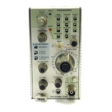
The major controls and connectors
for
operation
of
the
7D11
are
located on the
front
panel
of
the
unit.
Two
controls located inside the
unit
for
auxiliary functions
are
described in the General Operating I
nformation
section.
The front-panel controls
and
connectors
are
identified in
Fig. 1-2;
their
functions
are
as
follows:
®
GJ
COUNT
MODE Switch
Selects mode
of
operation
and
clock-signal
source
for
Time
count
mode.
o B
SWEEP
DELAY
MODE Switch
Selects the delay mode logic
for
time-base
unit.in
B Horizontal compartment
of
mainframe.
o
TRIGGER
SLOPE/LEVEL
Controls
Select slope
and
amplitude
point
of
input
signal
where
the
delay
is
initiated.
o
TRIG'D
Indicator
Lights when a trigger
is
produced.
o COUPLING Switch
Selects the method
of
coupling the
input
signal
to
the Trigger circuit.
o SOURCE Switch
Selects Trigger
input
signal source.
EVENTS
START
TRIGGER
SLOPE/LEVEL
Controls
Select slope
and
amplitude
point
of
input
signal
where the Events Start count
is
initiated.
DELAY
TIME
OR EVENTS Control
Selects delay
time
or
number
of
events counted.
Direction
of
rotation
selects increase
or
decrease
in delay
time
or
number
of
events.
RESET
Resets
the
DELAY
TIME
or
EVENTS
to
0000001.
FINE
DELAY
(ns) Dial
Selects analog delay
time
added
to
digital delay
time
selected
by
DELAY
TIME
OR
EVENTS
control.
Operating
Information-7D11
Service
G2J
DLY'D
TRIG
OUT
BNC connector
for
Delayed Trigger
output
signal.
(g]
EXT
1
MHz
IN
or
EVENTS
START
TRIG
IN
BNC connector
for
input
of
external 1 MHz
time·reference signal
or
input
of
Events Start
Trigger
input
signal. Connector
function
is
deter-
mined
by
setting
of
COUNT
MODE switch.
~
DLY
INTERVAL
OUT
BNC connector
for
Delay Interval
output
signal.
[!;]
EXT
TRIG
IN
BNC connector
for
external
input
to
Trigger
circuit
(selected
by
SOURCE switch in the
external positions).
GENERAL OPERATING INFORMATION
Signal Connection
In
general, probes
offer
the most convenient
means
of
connecting signals
to
the 7D11 external trigger inputs.
Tektronix
probes
are
shielded
to
prevent pickup
of
electro-
static interference. A 10X attenuation probe offers a high
input
impedance and allows the
circuit
under test
to
perform very close
to
normal operating conditions. Also, a
10X probe attenuates the
input
signal ten times.
Tektronix
probes
are
designed
to
monitor
the signal
source
with
minimum
circuit
loading. The
use
of
a probe
will,
however,
limit
the maximum trigger frequency range.
To
obtain maximum trigger bandwidth when using probes,
select a probe capable
of
compensating the
input
capaci-
tance; observe the grounding considerations given in the
probe manual. The probe-to-connector adapters
and
the
bayonet-ground
tip
provide the best frequency response.
In
high-frequency applications, requiring maximum over-
all bandwidth,
use
a coaxial cable terminated
at
both
ends
in the characteristic impedance
of
the cable.
To
maintain
the high-frequency characteristics
of
the applied signal,
use
high-quality low-loss cable. Resistive coaxial attenuators
can
be
used
to
minimize reflection
if
the applied signal
has
suitable amplitude.
High-level, low-frequency signals
can
be
connected
directly
to
the external trigger inputs
with
short, unshielded
leads.
When this method
is
used, establish a common
ground between the 7D
11
and the associated
equ
ipment.
The common ground provided
by
the line cords
is
usually
inadequate.
If
interference
is
excessive
with
unshielded
leads,
use
a coaxial cable
or
probe.
1-3


