PREPARATION
FORUSE
SAFETY
Before
connectingtheinstrumenttoa powersource,carefullyreadthe
following
infor-
mation,thenverifythattheproperpowercordisusedandtheproperlinefuseisinstalled
forpower
source.
Thespecifiedvoltageisshownatthe
left
sideofthepowercordon
therearpanel.Ifthepowercordisnotappliedforspecifiedvoltage,thereis
always
a
certain
amountofdanger
from
electricshock.
Line
voltage
This
instrumentoperatesusingAC-power
input
voltagesthat
100/120/220/240
V atfre-
quencies
from
50Hzto60Hz.
Power
cord
The
groundwireofthe3-wireACpowerplug
places
the
chassis
andhousingofthe
oscil-
loscope
atearthground.Donotattempttodefeatthegroundwireconnectionorfloat
theoscilloscope;todosomayposea greatsafety
hazard.
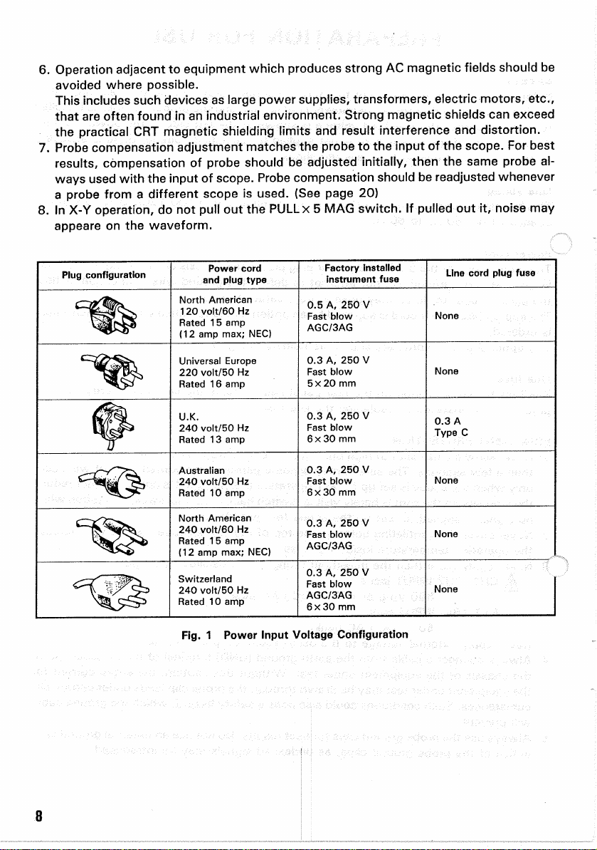
The
appropriatepowercordissuppliedbyan
option
thatisspecifiedwhentheinstrument
is
ordered.
The
optionalpowercordsare shownasfollowsinFig.1.
Line
fuse
The
fuseholderislocatedontherearpanelandcontainstheline
fuse.
Verifythatthe
properfuseisinstalledbyreplacingtheline
fuse.
EQUIPMENT
PROTECTION
1.
Neverallowa smallspotofhighbrilliancetoremainstationaryonthe
screen
formore
thana few
seconds.
The
screen
maybecomepermanentlyburned.A spotwilloccur
onlywhenthescopeissetupfor
X-Y
operationandnosignalisapplied.Eitherreduce
theintensitysothespotisbarely
visible,
switchbacktonormalsweepoperationwhen
nosignalisapplied,orsetupthescopeforspotblanking.
2.
Nevercovertheventilatingholesonthetopoftheoscilloscope,asthiswill
increase
theoperatingtemperatureinsidethe
case.
3.
Neverapplymorethanthemaximumratingtotheoscilloscopeinputs.
^
CH1,
CH2
INPUT
jacks:
800
Vp-por400V
(DC
+
AC
peak)
EXT
TRIG
INPUT
jack:
50
V
(DC
+
AC
peak)
Never
applyexternalvoltagetotheoscilloscope
output
terminals.
4.
Always
connecta cable
from
theearthground(GND)terminaloftheoscilloscopeto
the
chassis
oftheequipmentundertest.
Without
thiscaution,theentirecurrentfor
theequipmentundertestmaybedrawn
through
theprobeclip
leads
undercertaincir-
cumstances.
Such
conditionscould
also
posea safety
hazard,
whichthegroundcable
willprevent.
5.
Always
use
theprobegroundclipsforbest
results.
Donotuseanexternalgroundwire
inlieuoftheprobegroundclips,asundesiredsignalsmaybeintroduced.
7