NOYAFA NF-868 User manual

NF-868
Multipurpose LCD Display Cable Test & Inspection Instrument
INSTRUCTION MANUAL
Your wiring expert

Please read and learn safety instructions
before use or maintain the equipment
●
●
℃
●
●
●
●
●
●
The tester uses 9V battery for power supply .
Never put the equipment in the place with much dust, humidity
and high temperature (over 40 ).
Please use battery according to the specification; otherwise, it
may result in damage to equipment.
Please never dismount the equipment arbitrarily. The mainten
-ance and care shall be conducted by professional personnel.
The tester will shut off automatically if it does not work for
15 minutes in succession
Please take out the battery in launcher and receiver if the
equipment is not used for a long time so as to prevent that the
battery liquid is leaked in future.
Never use the equipment to detect power cord with electricity
(such as power supply circuit of 220V), other wise, it may result
in damage to equipment and personal injury.
Never conduct related operation of communication line in
thunderstorm weather so as to prevent lightning stroke and
impact on personal safety.
.
Your wiring expert

CONTENTS
Overview..................................................01
Main function characteristics.................02
Technical Parameters...............................02
Product interface and key introduction....04
Product operation method.......................05
................................06
......................................11
..............................15
..........................................17
Calibration and setup..............................18
Diagram of series products .....................20
a.Cable line-to-line test
b.Cable length test
c.Cable Line finding test
d.Crosstalk test
Your wiring expert

-01-
NF-868-R
POWER
NF-868-S
VOL
NF-868-M
Wire mapping
Cable Length
Scan Cable
Configure
Overview
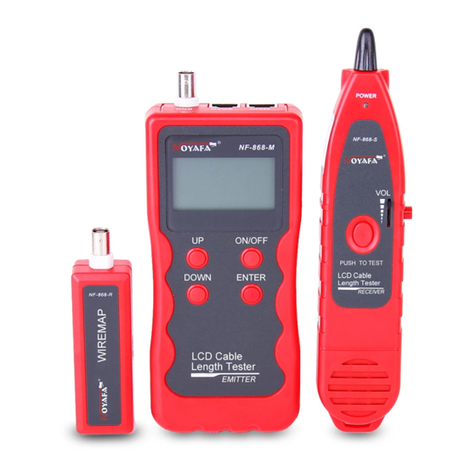
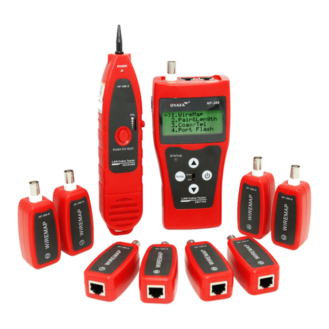
NF-868 type multipurpose communication cable tester & tracker
is a cable tester and tracker with more functions newly developed by
our company. The equipment is composed of three parts: main tester
(NF-868-M), receiver (NF-868-S) and remote identifier (NF-868-R).
The new equipment enjoys a smooth design, good feel and humanity
design. It has couples of circuit state testing functions including
length test, cable line finding, line-to-line, crosstalk and breaking
point and features fast and accurate, and thus serves as a practical
tool for low voltage system installation and maintenance technicians
of communication circuits and comprehensive wiring circuits. It is
widely used in the fields like telephone system, computer networks
and other metal lead circuits.
Remote identifier (NF-868-R)
Main tester (NF-868-M)
Receiver (NF-868-S)
PUSH TO TEST
Cable Tester
Wire Tracker
&
RECEIVER
DOWN
Cable Tester
Wire Tracker
&
EMITTER
UP ON/OFF
ENTER
WIREMAP
Your wiring expert

-02-
●
●
●
●
●
●
●
●
●
●
●
●
●
Capable to test open circuit, short circuit, cross connection, reverse
connection and pairing connection and broken wire positioning for
telephone cable, BNC cable and USB cable with M-S and M-R method,
and to visually display on LCD;
To perform crosstalk test on network cable for solving the potential
problem of slow speed;
To quickly find the target wire or cable among the plenty of network
cables, telephone cables, coaxial lines and other various kinds of wires;
Capable to measure length of network cable, coaxial cable, telephone
cable and USB cable with three method (M-S, M-R and OPEN), capable
to measure the cable at length of 1500m, and precision of measuring
cable length and position of broken line is up to 98%;
To make a accurate determination of open circuit position (left, right
or middle);
To perform cable tacking on exchanger or Router with power-on;
Low voltage prompt function is available in case of over low voltage
on the main unit;
Featuring simple control, large screen display and open-and-shut
test result;
Automatic delay power on-off and backlight function;
Lighting lamp enables to use in a dark environment;
Remote identifier is not necessary to perform length measurement
and pairing test;
Self-test function shall automatically make compensation due to
change of battery level and ambient temperature;
Single chip software watchdog design runs reliably.
Main function characteristics
Overall dimensions
Display
Main tester: 185X80X32mm; Receiver: 218X46X29mm
Remote identifier: 107X30X24mm;
Dot matrix 128X64 (Effective visible area 56X40mm);
(1).
(2).
Technical parameters
Your wiring expert

-03-
(3).
℃℃
Power supply
Main tester: 9V compound tandem cell;
receiver: 9V compound tandem cell;
(4).Testing cable types
(5).Detecting cable types
(6).Operating environment temperature/humidity
(7).Testing device interface
(8).Length measurement
(9).Length calibration
(10). Line sequence and cable failure positioning
(11). Line finding function
(12). Automatic delay of power on/off
STP/UTP 5E, 6E network cable, telephone cable, coaxial cable USB
signal cable and common metal wires connected with alligator clip;
STP/UTP 5E, 6E network cable, telephone cable, coaxial cable USB
signal cable and common metal wires connected with alligator clip;
-10 ~ +60 /20% ~ 70%;
Main unit: RJ45 (M), RJ45 (S), loop interface, RJ11, BNC connector,
USB B-type female interface;
Remote identifier: RJ45, RJ11, BNC connector, USB A-type female
interface;
Range: 1-1200m;
Calibration precision: 2% (+/-0.5m, or +/-1.5 feet); (calibration;
cable >10m) measurement precision: 3% ((+/-0.5m, or +/-1.5 feet);
(AMP, CAT5E, 6E cable material)
Display unit: meter, inch, yard;
User may use a cable at a known length to set a calibration coefficient,
and the calibration length is over 10m;
Used for Line finding two-core cable or cable with over two cores;
It will automatically power off in case of no operation within 15 minutes.
Your wiring expert

DOWN
Cable Tester
Wire Tracker
&
EMITTER
UP ON/OFF
ENTER
-04-
Main tester (NF-868-M)
Receiver (NF-868-S)
NF-868-M
POWER
NF-868-S
VOL
BNCSCAN
USB
RJ45
BNC
USB RJ11
Remote identifier (NF-868-R)
MAIN
RJ11
(M) (S)
Product interface and key introduction
Main unit port instructions
(1). Two RJ 45 interfaces on the main unit:
one of them is “MAIN” interface (M interface in short),
and the other is “SCAN” interface (S interface in
short); there are also RJ11 interface, USB interface
and BNC interface;
(2). M interface is used for measuring length and
others, but not for cable Line finding; S interface is
used for Line finding test and “local” connection test;
(3). RJ11 interface, USB interface and BNC interface
on the main unit are used for
line-to-line, length and Line
finding test.
Wire mapping
Cable Length
Scan Cable
Configure
PUSH TO TEST
Cable Tester
Wire Tracker
&
RECEIVER
NF-868-R
WIREMAP
Your wiring expert

Product operation method
5 seconds later, the following main interface is displayed:
There are four functional options in the main menu interface
-05-
---- ----identify
Figure 1
Powder-on display interface
Synchronous self test ( self test dynamically displayed in the line
from left to right)
------
(1).Connection test --- Connection and disconnection test: to test connection
of M, S R end-end cable and perform positioning of the failure;
(2).Length test---Pairing and length measurement: to verify cable length, open
circuit distance and pairing, crosstalk;
(3).Line finding---to find target cable among lots of network cables, telephone
cables, USB cables, coaxial cables and other kinds of wires;
(4).Parameter setup---Calibration and setup (Refer to the related chapters
below)Press “UP” and “DOWN” key to move the cursor “ ”upwards
and downwards to the corresponding items, and then press “ENTER”
key to enter corresponding test function.
Test method (Totally four methods)
(1). M-S method---When testing network
cable sequence and length with the main
unit, one end is connected with the “MAIN”
interface of the main unit, and the connection
of the other end with “SCAN” interface of the
main unit is as shown in Figure 1:
Wire mapping
Cable Length
Scan Cable
Configure
Your wiring expert

-06-
a.Cable line-to-line test:
(2).
(3).
(4).
M-R method:--- Using method of
testing network cable, telephone cable,
USB cable, coaxial cable with the main
unit and remote identifier is as shown
in Figure 2:
S method---Using method of Line
finding network cable with the main unit
is as shown in Figure 3:
Open circuit method---When
measuring test, one end is connected
with the main unit, and the using method
that the other end is neither connected
with the remote identifier nor “local” is
as shown in Figure 4:
Figure 2
Figure 3
Figure 4
Taking network test as an example: after entering connection test function,
press “ENTER” key to perform connection test of the equipment. At this
time, the following interface is shown indicating test is in process:
---- ----identify
Your wiring expert

Test result 1: Short circuit
Short mapping:
12345678
Cable open or
too Short !
12345678
M:
R: 12345678
Wire Map: Remote
-07-
If there is short circuit with the cable and terminal, the following interface is shown
(Short circuit with 3 and 6)
At this time, press any key to return to the main menu, and then press
“ENTER” key for re-test.
Please do not perform test again until short circuit problem solved.
Test result 2:Fail to find remote adapter (R) or local port (S) cable: if
the far end of the cable to be tested is not plugged in a remote adapter (R)
or when to perform local test, cable is not plugged into the local port (S),
the following interface is shown:
At this time, press any key to return to the main menu, and then press “ENTER”
key for re-test.
Test result 3:In case of correct connection, the testing device will
automatically detect the remote adapter (R) or local port (S) cable. If it detects
that the far end of the cable to be tested is with a remote adapter (R) or local
port cable, the following interface is shown:
At this time, press any key to return to the main menu, and then press “ENTER”
key for re-test.
Wherein: “R” line indicates pin position of the remote adapter RJ45 port;
Wherein: “S” line indicates pin position of local RJ45 port;
Wherein: “M” line indicates pin position of local main end RJ45 port.
Your wiring expert

12345678
M:
R: 123XX678
12X45X78
M:
S: 12345678
12X45678
M:
S: 12X45678
-08-
Test result 4: In case of open circuit existing on far end of the cable,
the following interface is shown:
In the figure, “X” shown in “4” and “5” pin position in “R” line, indicates there is
open circuit in “4” and “5” pin of the remote pin.
At this time, press any key to return to the main menu, and then press“ENTER”
key for re-test.
If to test the connection with the remote adapter (R), because the test
is performed through the paired two cable cores, remote open circuit is always
shown in pairing. For example, in the figure above, it means open circuit is with
either or both of “pin “4” and “5”. If clarification is needed, please take the main
unit for remote test.
Note:
Test result 5: In case of open circuit existing on near end of
the cable, the following interface is shown:
At this time, press any key to return to the main menu, and then press“ENER”
key for re-test.
In the figure, “X” shown in “3” and “6” pin position in “M” line, indicates there is
open circuit in “3” and “6” pin of the near pin.
Test result 6: In case of open circuit existing on middle part
of the cable, the following interface is shown:
In the figure, “X” shown in “3” pin position in “M” and “S” line, indicates there is
open circuit in “3” pin of the middle part of the cable. If to further find position of
the open circuit, please use pairing and length measurement function of this
device. Refer to the related chapter below.
At this time, press any key to return to the main menu, and then press “ENTER”
key for re-test.
Wire Map: Remote
Wire Map: Local
Wire Map: Local
Your wiring expert

Test result7: USB cable line sequence test
XX34XX
M:
R: 123456
1234
M:
R: 1234
-09-
At this time, press any key to return to the main menu, and then press“ENTER”
key for re-test.
Test result 8: 2-core telephone cable line sequence test
At this time, press any key to return to the main menu, and then press “ENTER”
key for re-test.
Test result 9: BNC coaxial cable line sequence test
When power on the main tester and enter the main menu of test, press “UP”
and “DOWN” key to move cursor to “Parameter configuration” item, and
then press “ENTER” key. After that, move the cursor to “Type” and press
“ENTER” key to select USB cable, and then return to the main menu to select
“Connection test”. By now, you can perform test on USB cable line sequence.
The following interface will be shown:
“”
When power on the main tester and enter the main menu of test, press “UP”
and “DOWN” key to move cursor to “Parameter configuration” item, and
then press “ENTER” key. After that, move the cursor to “Type” and press
“ENTER” key to select telephone cable, and then return to the main menu to
select “Connection test”. By now, you can perform test on telephone cable
line sequence. The following interface will be shown:
“”
When power on the main tester and enter the main menu of test, press “UP”
and “DOWN” key to move cursor to “Parameter configuration” item, and
then press “ENTER” key. After that, move the cursor to “Type” and press
“ENTER” key to select coaxial cable, and then return to the main menu to
select “Connection test”. By now, you can perform test on.
“”
Wire Map: Remote
Wire Map: Remote
Your wiring expert

-10-
12345678
12345678
12
M:
R: 12
coaxial line sequence. The following interface will be shown:
At this time, press any key to return to the main menu, and then press“ENTER”
key for re-test.
Special use: In case of exchanger power-on, the main unit
cantestlinesequenceoftheconnectingcables
Take network cable as an example: one end of the cable is connected with
“MAIN” interface of the main unit, and other end is connected with exchanger
interface. And direct connection test can be performed. If the exchanger
interface tested is reliably connected, the following interfaceis shown
(exchanger interface is 8-core):
In case of open circuit with line 1 and 2 of the exchanger tested, the following
interface is shown (exchanger interface is 8-core):
Wire Map: Remote
Short mapping:
Short mapping:
Your wiring expert

---- ----identify
-11-
12345678
12 Open 105.5m
78 Open 105.2m
36 Open 105.3m
45 Open 105.0m
b.Cable length test:
No matter whether the cable far end is connected with a remote adapter (R),
the equipment can perform pairing and length measuring. Therefore, during
the whole measuring process, the remote identifier (R) can be connected all
the time to avoid repeated plugging. Firstly insert one end of the cable to be
tested into “M” port in the main tester. When entering length testing function,
press “ENTER” key to perform pairing and length testing with the equipment.
At this time, the following interface is shown:
Note: Due to different technical parameters with different branded cables,
users are recommended to use dynamic calibration function of the equipment
before measuring length (Refer to the related chapter for more details.).
Test result 1: Short circuit
If there is short circuit with the cable and terminal, the following interface is
shown (Short circuit with 2 and 3)
At this time, press any key to return to the main menu, and then press “ENTER”
key for re-test.
Please do not perform test again until short circuit problem solved.
Test result 2 In case of normal pairing and length test,
the following interface is shown:
:
Wherein, the digits after pairing (e.g. 12) is the cable number of pairing. “Open” i
ndicates only one end of the twisted-pair cable is connected with “M” end, and
those follow “Open” are lengths of the cable.
At this time, press any key to return to the main menu, and then press “ENTER”
key for re-test.
Short mapping:
Your wiring expert

-12-
12 MS-105.5m
78 MS-105.2m
36 MS-105.3m
45 MS-105.0m
12 MR-105.5m
7 105.2m
36 MR-105.3m
45 MR-105.0m
8 105.5m
12 MR-105.5m
36 MR-105.3m
45 MR-105.0m
78 MR-105.2m
Test result 3:
Insert one end the twisted-pair cable into “M” port, insert the other into “S” port,
select twisted-pair cable test mode, return to the main menu, and select length
test, and then press “ENTER” key to perform pairing and length test. The following
interface is shown:
At this time, press any key to return to the main menu, and then press “ENTER”
key for re-test.
Test result 4:
Insert one end the twisted-pair cable into “M” port, insert the other into “R” port,
select twisted-pair cable test mode, return to the main menu, and select length
test, and then press “ENTER” key to perform pairing and length test. The
following interface is shown:
At this time, press any key to return to the main menu, and then press “ENTER”
key for re-test.
Test result 5: Abnormal pairing and length test:
In case of unpaired lines found during pairing and length test, the following
paired lines will be firstly shown:
Wherein ,the last line shows line #7 only, and line #8 fails to find a pair. At this
time, if to press “DOWN” key, the unpaired line #8 length will be shown as below:
At this time, press any key to return to the main menu, and then press “ENTER”
key for re-test.
Your wiring expert

-13-
11MR-10. m
21
MR-10. m
31
MR-10. m
41
MR-10. m
(2).If to insert one end of the USB cable to be tested into “USB(4)” port of the
main tester, the other end is an open circuit, select USB test mode, return to
the main menu, and select length test, and then press “ENTER” key to perform
length test with the equipment, the following interface will be shown:
11Open 10. m
41
Open 10. m
21
Open 10. m
31
Open 10. m
10
MR-0. m
20
MR-0. m
31
MR-10. m
41
MR-10. m
Test result 6: USB cable length test
(1). If to insert one end of the USB cable to be tested into “USB(4)” port of
the main tester, insert the other end into “USB(4)” port of “R” end, select
USB test mode, return to the main menu, and select length test, and then
press “ENTER” key to perform length test with the equipment, the following
interface will be shown:
It indicates that length of USB cable is 10.1m. At this time, press any key to
return to the main menu, and then press “ENTER” key for re-test.
It indicates that length of USB cable is 10.1m. At this time, press any key to
return to the main menu, and then press “ENTER” key for re-test.
Test result 7: RJ11(TEL) cable length test
(1).If to insert one end of the RJ11 cable to be tested into “TEL(6)” port of the
main tester, insert the other end into “TEL(6)” port of “R” end, select telephone
cable test mode, return to the main menu, and select length test, and then
press “ENTER” key to perform length test with the equipment, the following
interface will be shown:
Your wiring expert

-14-
(2).If to insert one end of the RJ11 cable to be tested into “TEL(6)” port of the
main tester, the other end is an open circuit, select telephone cable test mode,
return to the main menu, and select length test, and then press “ENTER” key to
perform length test with the equipment, the following interface will be shown:
10Open 0. m
41
Open 10. m
20
Open 0. m
31
Open 10. m
50Open 0. m
60
Open 0. m
50
MR-0. m
60
MR-0. m
1 10.1
Open m
2 10.1
Open m
And then press “UP” or “DOWN” key, the following interface will further
be shown:
It indicates that length of telephone cable is 10.1m. At this time, press any key
to return to the main menu, and then press “ENTER” key for re-test.
And then press “UP” or “DOWN” key, the following interface will further be shown:
It indicates that length of telephone cable is 10.1m. At this time, press anykey to
return to the main menu, and then press “ENTER” key for re-test.
Test result 8: BNC cable length test
If to insert one end of the BNC cable to be tested into “BNC(2)” port of the main
tester, the other end is an open circuit, select BNC cable test mode, return to the
main menu, and select length test, and then press “ENTER” key to perform length
test with the equipment, the following interface will be shown: (Coaxial cable
length can be tested only with open circuit test mode, and other methods are
incapable to test its length)
It indicates that length of BNC cable is 10.1m. At this time, press any key to
return to the main menu, and then press “ENTER” key for re-test.
Your wiring expert

-15-
Scanning...
c. Line finding test:
After powering on the main tester and entering main test menu, press “UP”,
“DOWN” key to move cursor to “Line finding” item, and then press
“ENTER” key to find the line. The following interface will be shown:
“”
Connect the cable to be found with the corresponding RJ45(S) port, RJ11,
USB and BNC interface of the emitter. Take network line finding as an example:
connect the network cable to be found with S port of the emitter, move
cursor to “line finding” item, and press “ENTER” key to perform line finding
test as shown in the figure below:
“”
Your wiring expert

-16-
Use method of receiver
Remove the cover of battery pack, properly place in 9V battery, replace the
battery cover, hold the receiver and press and hold “Test” key with the thumb,
and then keep the detecting head close to the cable to find the target cable
among lots of cables. When the detecting head goes close to the target cable,
it beeps, and the same time the signal indicator “POWER” lights. Compare
loudness of beeps and brightness degree of the signal indicator. The cable
with loudest beeps and the highest brightness is just the target cable to find.
In a dark test environment, you may turn on lighting lamp on the receiver for
easy test as shown in the figure below:
Your wiring expert

M:
R:
3
4
5
6
3
4
5
6
12345678
12345678
-17-
d. Crosstalk test
As shown the figure below: it shows 3, 6 and 4, 5 with crosstalk. The line
pair with crosstalk will flash to indicate failure. In the line pair with crosstalk,
end-to-end connection is correct. However the connected lines are from
different line pairs. Line pair crosstalk will cause an over large crosstalk,
and therefore, network operation is interfered.
Connection diagram of crosstalk line pair
Crosstalk interface is shown as below:
Crosstalk line pair flashes
Note: In case of the non-twisted-pair cable like telephone cable,
due to over large crosstalk, it generally shown as crosstalk.
Wire Map: Remote
Your wiring expert
Other manuals for NF-868
1
Table of contents
Other NOYAFA Test Equipment manuals