TEL AFA 1000 User manual

1
AFA 1000
FUME HOOD ALARMS
Operating and Instruction Manual
Model AFA1000 / 1
• Digital display
• 1 Output relay
• 3 Input relays
• Com port
Used for alarm indication and monitoring on
Fume Hoods
1/MK3/FH/USPSU
250804

2
Table of contents :-
Section
Description
Page
1
Operator display panel 3
2
Connection details
4
3
General description – overview
5 to 8
4
Installation
8
5
Start-up / Calibration
9 to 11
6
Monitor configuration
11
7
Events – actions
12 to 15
8
Dimensions
16 to 17
9
In-line sensor installation
18 to 19
10
Wiring diagram
20
11
Spares
21
12
Limitation of Warranty and Liability
22
13
Contact us
22

3
Velocity Bar Graph or
Alarm Time Line
Velocity display fpm or m/sec
LED indicators
Function and up/down buttons
for Menu Configuration and
Calibration.
ENTER – also used as
Mute button for audible alarm
1.0 Operator Display Panel

4
120V
PSU
120V / 15V DC
Plug – in power adapter for
120V socket
Power requirement - 110mA
@ 120v AC Supply
Flying lead with plug
connection for PCB
15 V DC
Flying lead with RJ11
plug connection for PCB
and SM6 airflow sensor
12V DC
Sash High
Proximity switch
( Optional )
SM6 or Inline
Airflow Sensor
OUTPUT
RELAY
R1
SENSOR
SOCKET
15V DC
POWER
SUPPLY
INPUT
REFER TO
INSTALLATION
INSTRUCTIONS
BEFORE
CONNECTING
MADE IN ENGLAND
www.tel-uk.com
TEL
INPUT 3
Blu
Blk
Brn
AFA 1000 USA
Sash High
Micro - switch
( Optional )
IDC
14-way
Connector
for remote
Interface Box
( Optional )
INPUT 2
INPUT 1
RS 232
Com Port
Notes :-
Inputs 1 2 & 3 are volt free inputs. (Max line resistance 4.7K ohms) (Short circuit current 5mA DC)
Relay output R1 is a power limited volt free contact. Contact rating 30VAC / 42VDC Max
Primary power requirement - 110mA @ 120VAC ( 3A Fused supply recommended ).
2.0 Connection details
s/w
+
-

5
3.0 General Description
All systems comprise of the following components :-
1 – In-line Airflow Sensor,
1 – AFA1000 Alarm unit,
1 – AC power supply
If the Sash Alarm System option is included there will also be a sash micro switch
or proximity switch.
Operator Features --- the alarm has the following operator features :-
Digital Display
The digital display is a back-lit, full graphic unit with a visual display of approx
2.2" x 1.18 ". The display operates through the software allowing the generation
of figures, wording and Icons.
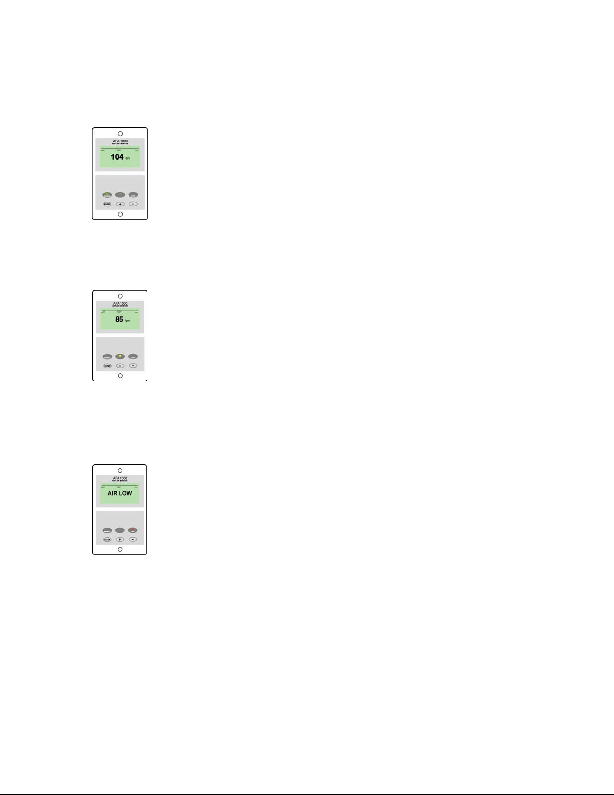
The display shows the fume hood face velocity in m/sec or fpm when enabled
or the alternative with no velocity reading but showing LOW AIR / NORMAL as
continuous display.
All of the above are configurable via the alarm key pad.
An ‘ event time line ’ segmented into 20 x 3 minute segments will scroll across
the display ( when enabled) .This takes the form of a graphical ‘ blip’ that will
progress from the right hand side to the left hand side – representing events that
have occurred during the past hour. On the standard alarm this will be limited to
airflow alarms but other alarms are available.
The alternative to the event time line is a dynamic ‘ bar graph ’ representing the
face velocity
The display shows a Horn icon ( with line through it ) when the audible alarm is in
the Muted condition
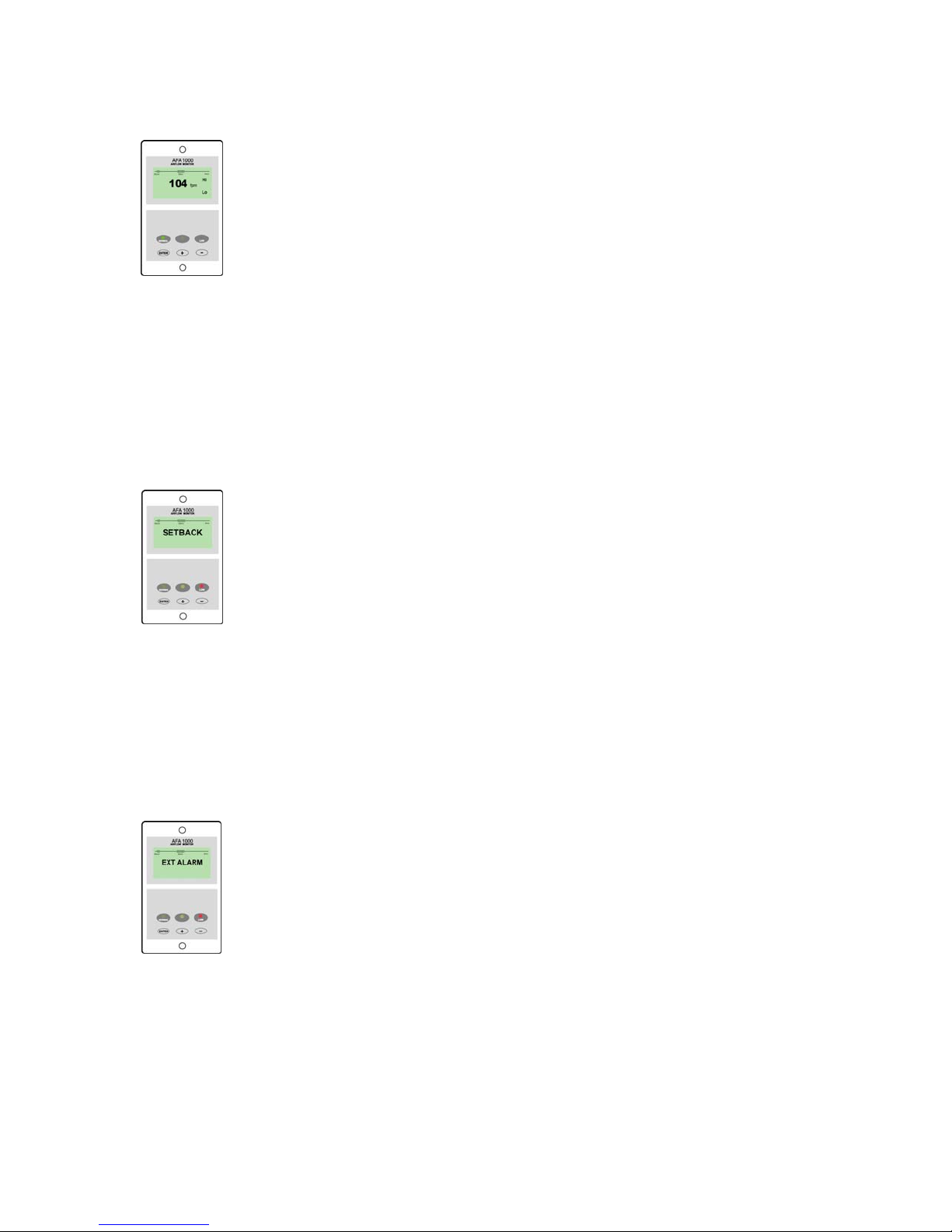
Sash High – will be displayed when the Sash alarm is enabled and the sash
is raised above the max safe working opening.
This display will alternate on/off with the velocity reading.
Ext Alarm – will be displayed when the external alarm input is activated ( when
enabled )
This display will alternate on/off with the velocity reading
Low Air - will be displayed if the airflow is less than the Low air alarm point.
This display will alternate on/off with the velocity reading

6
High Air - will be displayed if the airflow is more than the High air alarm point.
This display will alternate on/off with the velocity reading
Set-back - will be displayed if the night set-back function is activated ( when
enabled )
This display will alternate on/off with the velocity reading
Disabled - will be displayed if the alarm disable function is activated ( when
enabled )
This display will alternate on/off with the velocity reading
LED Indicators ---- the alarm unit has three LED indicators :-
Red -- Low
Amber -- Caution
Green -- Normal
Audible Alarm sounder -- the alarm has an audible alarm sounder with local or
remote Mute facility
Enter --- the alarm has an Enter button -- this is multi-functional as follows :-
Press Enter momentarily when alarm is sounding will mute the alarm.
The horn can be permanently disabled using the configuration menu.
When this option is selected the Horn Icon with the word OFF will
permanently appear on the display.
Press Enter for 5 secs will gain access to Calibration and
Configuration menus ( both menus password protected )
+ / - -- the alarm has + / - buttons that can be used to scroll through the
calibration and configuration menu or to select options or values

7
External Connections -- the alarm unit has the following connection points :-
Input 1 --- volt free relay input configurable for normally closed or normally
open relays
This input can be configured as :-
Alarm disable
Night set-back
External alarm
Sash High
High / Low
Input 2 --- volt free relay input configurable for normally closed or normally
open relays
This input can be configured as :-
Alarm disable
Night set-back
External alarm
Sash High
High / Low
Input 3 --- volt free relay input configurable for normally closed or normally open
relays
This input can be configured as :-
Alarm disable
Night set-back
External alarm
Sash High
High / Low
Output 1 --- volt free relay output configurable as normally closed or normally
open relay .
Com Port --- for communications to building computer system ( BMS)
Power supply --- low voltage DC power supply
Airflow Sensor --- connection socket for the face velocity airflow sensor.

8
4.0 Installation
Follow the instructions below for installing the unit. :-
1. Fit the alarm to the Fume Hood using the cut-out details provided with the
unit --- see page 16 to 17
2. Fit the airflow sensor to the Fume Hood using the cut out and installation
details provided --- see page 18
3. Connect the ‘telephone style’ airflow sensor plug-in cable to the sensor
and the back of the alarm unit --- see typical connection diagram on page
19 & 20
4. Plug in the power adapter to a 120V AC power socket and connect the
power supply connector to the alarm unit --- see typical connection
diagram on page 19 & 20
5.0 Start up / Calibration
1. Power up the alarm and it then performs a self test on the display and all
indicators etc ( approx 5 sec ) , then wait at least 30 secs while the sensor
temperature stabilizes.
2. If the alarm has not been calibrated it will display ‘ Requires setup ’ –
press ENTER to continue and in the Main Menu use the +/- buttons on the
alarm face to select ‘ SETUP ‘ and then press the ENTER button.
3. To calibrate the alarm it is necessary to use a pre-calibrated anemometer
which can be used to give an accurate measurement of the actual face
velocity of the hood at two sample values. The lower value is taken with
the sash at the normal working height and is ‘captured’ by the alarm.

9
A higher value is taken with the sash partially closed and this is also
‘captured’ by the alarm. From these two known points the alarm will track
the face velocity over the whole range of the hood face velocities.
Before starting the calibration of the alarm please read the ‘Calibration
Notes ‘ below.
When you are ready to start the calibration proceed as follows :-
a. In the Setup Menu select ‘CALIBRATION’ and press the ENTER
button
b. At this stage you will be requested to enter the PASSWORD. Use
the +/- buttons to select the individual digits in turn and press
ENTER for each digit.
If the password is correct the unit will go to the Calibration mode. If
the password is not correct you will be requested to try again --- on
the third wrong password entry the calibration menu will lock out for
10 mins
NOTE:- If you enter the Calibration Menu by accident :-
press the + & - buttons at the same time to escape back to the
Main Menu
c. When in the calibration mode follow the instructions on the display
screen to carry out the calibration of the unit. See ‘Calibration
Notes’ below for hints on successful calibration.
d. When the calibration is complete the unit will return to the Main
Menu.
e. From the Main Menu use the +/- buttons on the alarm face select ‘
RUN ’ and then press the ENTER button.
The unit will now function and display the measured Fume Hood face
velocity
Note:- To re-enter the Menu functions press and hold the ENTER button until
the Main Menu appears on the display

10
5.1 Calibration Notes :-
1. When using a standard Fume Hoods with Vertical Sliding sashes open
the sash to the normal max safe working height for the Low Air sample.
2. For the Higher Air sample close the sash to approx 50% of the opening
used for the Lower Air sample. If the Higher air sample value is too close
to the Lower Air sample the alarm will detect this and ask you to repeat
with a higher value. To do this close the sash a little more and repeat the
sample. Avoid closing the sash below 4 ins.
A difference of at least 50 fpm or more between the high and low velocity
points will create the best accuracy over the whole operating range.
3. The face velocity readings on the open sash may vary at different points
on the measuring grid by up to 20fpm. This is quite acceptable in terms of
the fume hood performance so long as no individual point is below the
designated Low Air alarm point .The figure entered for the calibration point
can be taken as the average value of all the measuring grid readings or
could be taken as the individual lowest point on the grid. For most fume
hoods this low point is on the bottom row in the centre and is a convenient
position to measure and for future reference when checking the alarm
during annual maintenance.
4. Take time when measuring the face velocities for the calibration procedure
to allow for the velocities across the open sash to stabilize. If the velocities
are changing or are turbulent during the sampling period the alarm will
detect this and ask you to repeat the sample.
5. When using a Fume Hood with Horizontal Sliding sashes open the
sashes to the normal max safe working opening for the Low Air sample.
When calibrating or re-calibrating the alarm it is important to ensure that the ‘Vent
kit’ is connected to the In-line airflow sensor on the fume hood. If the vent kit is
not connected the sensor will not ‘see’ a change in the airflow during the
calibration procedure. If this occurs the alarm will detect this an bring up a
warning on the display asking you to ‘check the sensor’
If the sensor cable is not connected the alarm will display SENSOR ERROR and
you will not be able to proceed with the calibration.

11
6.0 Monitor Configuration
The configuration of the various functions and the calibration of the alarm face
velocity display is menu driven. Access to the Calibration and Configure menu
will be via separate passwords (4 digit numbers ). The numbers are factory set to
0000 and 0000 . These numbers can be changed via the pushbuttons and
display from the Setup Menu.
NOTE:- If you enter the Configure or Password Menu by accident :- press
the + & - buttons at the same time to escape back to the Main Menu
The menus and sub–menus are in ‘ plain language ’ and incorporate brief
instructions where appropriate.
See ‘ Menu Block Diagrams ‘ for a step by step view of the menu structure
12
7.0 Events / actions
Normal airflow
• Meter reading above warning level ( e.g. > 90fpm )
• Green LED on
Warning airflow
• Meter reads between warning level and air fail level ( e.g. > 80fpm and
< 90fpm )
• Amber LED on
Low airflow
• Meter reads below alarm level for longer than the warning to low air delay
time
• LOW AIR toggles on / off with display
• Red LED on ( Flashing )
• Audible alarm sounds -- can be muted via Enter pushbutton
• Low air relay operates ( if configured )
Reset : -- when airflow rises 4fpm above Low air level for longer than the low air
to warning air delay time the Low air alarm resets automatically

13
High airflow
If configured :-
• High Air toggles on / off with display
• Audible alarm sounds – can be muted via Enter pushbutton)
Sash High
• When the input configured as Sash High is activated
• Amber LED on
• Sash High – toggles on / off with velocity display
• Audible alarm sounds
• Audible can be muted via Enter pushbutton -- this silences the alarm and
initiates a repeat timer ( if configured ). After the delay time the alarm re-
sounds ( and can be re-muted). During this time the Amber LED flashes on /
off.
• Sash High relay operates ( if configured )
Reset when Sash lowered to safe position and input de-activated.
14
High / Low
• When input configured as High/Low is activated
• Display Icon shows High or Low
• High / Low relay operates ( if configured )
This function is designed for two speed fan operation or two position damper
operation switched via a micro switch or proximity switch activated at a given
position on the sash.
Night set-back
• When input configured as Night set-back is activated
• Night set-back Icon is displayed
• Red LED on ( Flashing)
• Reduced Low air alarm ( if configured )
• Audible alarm muted
• Mute Icon shown on display
External alarm
• When input configured as External alarm is activated
• Red LED on ( Flashing) – ( if configured )
• Ext Alarm toggles on /off with display -- ( if configured )
• Audible alarm sounds – can be muted via Enter pushbutton
• External alarm relay operates ( if configured)

15
Alarm disable
• When input configured as Alarm disable is activated
• Alarm disabled is displayed
• Red LED on ( Flashing)
• Audible alarm muted
• Mute Icon shown on display
Audible alarm Mute
• When the audible alarm is muted via the Enter button - an Icon ( horn with
forward slash) is shown on the display.

16
8.0 Dimensions
3.19″
(81mm)
5.2 ″
(132mm)
Alarm Panel
Dimensions
Panel Cutout
Dimensions
3.00″x 2.00″
4.37 ″
(111mm)
R1
15V
T
EL
s1
IDC
2
3
232
1.14
″
(29mm)
1.14
″
(29mm)
2.91
″
(74mm)
1.89 ″
(48mm) 0.75 ″
(19mm) 0.38 ″
(9.75mm)
Front
View Rear
View Side
View
1.59
″
(40.5mm) 1.59
″
(40.5mm)
2 x Fixing Holes
for 2 x No. 6
Self tapping screws provided
3.00″
(76.2mm)
2.00
″
(50.8mm)
4.37
″
(111mm)

17
Airflow Alarm
Vent Tube Hole
Airflow Alarm
Vent Tube Hole
Concept or Pioneer
Fume Hood
SafeAire
Fume
Hood

18
9.0 In – line Airflow Sensor Installation
The in-line sensor kit comprises of the following components
Select the correct length of Hose to suit the installation .
The Cross Hatch Washer is fixed inside of the female coupling.

19
It is very important to position the In-line airflow sensor in the correct position to
give long term stable reading of the face velocity. Please read the
INSTALLATION NOTES below and if in doubt contact us for further advice.
INSTALLATION NOTES :-
1. The In-line sensor must be positioned where it can " see " the room pressure
of the laboratory.
1” Threaded coupling should be mounted through a 1" hole in the front face
of the side wall post. Cross hatch washer is pre- fitted between Hose & female
coupling.
1” Elbow should be mounted through a 1" hole in the inner lining side wall.
The ideal position for this elbow is 4" back from the sash glass and 4"
higher than the normal sash opening height through the inner side wall.
2 The sensor should not be mounted in a position where it is subject to drafts
from the laboratory air input or ventilation system.

20
10.0 Typical Wiring Diagram --- (Alarm only)
120V
PSU
120V / 15V DC
Plug – in power adapter for
120V socket
Power requirement –
110mA @ 120v AC Supply
Flying lead with plug
connection for PCB
15 V DC
Flying lead with RJ11
plug connection for PCB
and SM6 airflow sensor
12V DC
Sash High
Proximity switch
( Optional )
SM6 or Inline
Airflow Sensor
OUTPUT
RELAY
R1
SENSOR
SOCKET
15V DC
POWER
SUPPLY
INPUT
REFER TO
INSTALLATION
INSTRUCTIONS
BEFORE
CONNECTING
MADE IN ENGLAND
www.tel-uk.com
TEL
INPUT 3
Blu
Blk
Brn
AFA 1000 USA
Sash High
Micro - switch
( Optional )
IDC
14-way
Connector
for remote
Interface Box
( Optional )
INPUT 2
INPUT 1
RS 232
Com Port s/w
+
-
Table of contents
Other TEL Security System manuals


