Telair ENERGY 4010B Operation instructions

Energy 4010 B Vers. 022
1
GB
INDEX
USER'S OPERATING INSTRUCTION
AND INSTALLATION MANUAL
GB
ENERGY 4010B
v. 001
–
Februar
y
2011
GENERATORS

Energy 4010 B Vers. 001
GB
2
INDEX
1 FOREWORD ..................................................................................................................................... 5
1.1 Purpose and scope of this manual ............................................................................................. 5
1.2 Symbols and Definitions ............................................................................................................. 5
1.3 General Information .................................................................................................................... 5
2 GENERATING SET IDENTIFICATION DATA................................................................................... 6
2.1 Components (Fig. 1) ................................................................................................................... 6
2.2 Identification plate (Fig. 2) .......................................................................................................... 6
2.3 Overall dimensions ..................................................................................................................... 6
2.4 Technical specifications.............................................................................................................. 7
3 SHIPPING, HANDLING, STORAGE .................................................................................................7
3.1 Storage ....................................................................................................................................... 7
3.2 Weight......................................................................................................................................... 7
3.3 Handling...................................................................................................................................... 8
4 INSTALLATION ................................................................................................................................. 8
4.1 Preliminary information ............................................................................................................... 8
4.2 Instructions for fastening the generating set............................................................................... 8
4.2.1 Hanging assembly ………..….…………………………………………………………………..8
4.2.2 Floor fastening …..………….……..…………..…………………………………………………9
4.3 Wiring connection instructions .................................................................................................. 10
4.4 Battery connection .................................................................................................................... 10
4.5 Electric Load connection........................................................................................................... 11
4.6 Auxiliary electric cable connection............................................................................................ 12
4.7 Electronic control panel connection .......................................................................................... 12
4.8 Auxiliary (optional) fuel pump connection .................................................................................12
4.9 (Optional) tank installation instructions ..................................................................................... 13
4.10 Fuel reserve............................................................................................................................ 14
4.11 Battery charger ....................................................................................................................... 14
4.11.1 Auxiliary Battery Charger ................................................................................................. 14
4.12 Connecting an additional silencer........................................................................................... 15
4.13 Connecting an External Network Relay .................................................................................. 16
5 OPERATING INSTRUCTIONS........................................................................................................ 16
5.1 Machine safety.......................................................................................................................... 16
6 USING THE GENERATING SET ....................................................................................................17
6.1 Starting up the generating set................................................................................................... 17
6.2 Turning the generating sets off ................................................................................................. 18
6.3 Information on not recommended uses .................................................................................... 18
6.4 Useful tips ................................................................................................................................. 18
6.5 Control and alarm functions (Fig. 24) ....................................................................................... 18
6.6 Control panel alarm causes and resetting ................................................................................ 18
6.7 Automatic Version (optional). ………………………………………………………………………20
6.8 MANUAL operation .………………………………………………………………………………….20
6.9 AUTOMATIC OPERATION…………………………………………………………………………..20
7 MAINTENANCE INSTRUCTIONS................................................................................................... 21
7.1 Service check list ...................................................................................................................... 21
7.2 Maintenance not requiring specialised personnel..................................................................... 21
7.3 Checking the engine oil level .................................................................................................... 21

Vers. 001 Energy 4010 B
G
B
3
7.4 Maintenance operations to be carried out by qualified personnel............................................. 22
7.4.1 Engine oil replacement ...................................................................................................... 22
7.4.2 Air filter maintenance ......................................................................................................... 22
7.4.3 Spark plug maintenance .................................................................................................... 22
7.4.4 Voltage adjustment ............................................................................................................ 22
8 ROUTINE MAINTENANCE SCHEDULE ......................................................................................... 23
9 PROLONGED INACTIVITY ............................................................................................................. 24
10 DISMANTLING .............................................................................................................................. 24
11 RECOMMENDED FIRE-FIGHTING EQUIPMENT ........................................................................ 24
GENERAL WARRANTY TERMS ......................................................................................................... 25
WIRING DIAGRAM ENERGY 4010 B .................................................................................................. 26
DRAWING FOR SPARE PARTS LIST ENERGY 4010 B .................................................................... 28
When the generator remains idle for at least three weeks, old unleaded
petrol sediments could build up inside the carburettor. These sediments
can seriously damage the engine and it is therefore COMPULSORY that
the carburettor be completely emptied prior to a long period of non-use:
do this by turning off the fuel tap and running the generator set until it
stops.
It is also essential that you never use old unleaded petrol, as it can
undergo chemical modifications and seriously damage the engine.
Failure to observe these instructions automatically renders the
WARRANTY NULL AND VOID.

Energy 4010 B Vers. 001
G
B
4
Via E. Majorana , 49 48022 Lugo (RA) ITALY
"CE" COMPLIANCE STATEMENT
Under Machine Directive 89/392/ EEC, attachment II A
We hereby represent that the generating set - the data concerning which are specified below - has been
designed and built to correspond to the essential safety and health requirements laid down by the European
Directive on Machine Safety.
This statement shall no longer be valid if any changes are introduced in the machine without our written
approval.
Machine: GENERATOR-SET
Model: ENERGY 4010 B
Serial number: ………………………...
Reference Directive:
Machine Directive (89/392/ EEC) version 91/31/ EEC
Low Voltage Directive (73/23/ EEC)
Electro-magnetic Compatibility (89/336\ CEE) version 93/31/ EEC
Harmonised standards applied, in particular: EN 292-1; EN 292-2; EN 60204-1
DATE ........07/12/2010..........
THE PRESIDENT

Vers. 001 Energy 4010 B
G
B
5
1 FOREWORD
Refer carefully to this
manual before performing any operation on
the power generator set.
1.1 Purpose and scope of this manual
This manual has been drawn up by the
Manufacturer in order to provide basic
information and instructions for performing every
operation for servicing and using the generating
set in a proper and safe manner.
It is an integral part of the generating set
equipment, must be kept with care throughout
the life of the same, and must be protected
against any agent which could damage it.
It must follow the generating set if this is installed
on a new vehicle, or if its ownership changes
hands.
The information in this manual is addressed to
the personnel in charge of installing the
generating set, and to all those involved in its
maintenance and use.
This manual sets out the purpose the machine
was designed for, and contains all the
information required to guarantee that it is used
in a safe and proper manner.
Constant compliance with the instructions laid
down here will guarantee the safety of the user,
operating economy and longer life of the
machine.
To facilitate reference, this manual has been
subdivided into chapters specifying the main
notions contained therein; for quick consultation,
refer to the table of contents.
The most important parts of the text are in bold
letters and preceded by symbols described here
below.
It is strongly recommended that you read the
contents of this manual and the reference
documents carefully; doing so is essential to the
correct long-term performance and reliability of
the generator set and the prevention of injury
and/or damage.
Note: The information contained in this
publication was correct at the time it went to
print, but may be modified without advance
notice.
1.2 Symbols and Definitions
"Graphic safety symbols” have been employed in
this booklet to identify different levels of danger
or important information.
This means that you must
pay attention to avoid serious consequences
which might lead to serious accidents or damage
the health of the operators.
This means a potentially
hazardous situation which could lead to
accidents or damage to property.
This calls the user’s attention
to a potentially dangerous situation which could
cause malfunction or damage the machine.
The drawings are only provided by way of
example.
Even though the machine you actually have may
differ from the illustrations contained in this
manual, safety and information about the same
are guaranteed.
The manufacturer, as part of his policy of
constant product development and updating,
may introduce changes without giving any notice.
1.3 General Information
The ENERGY generating set has been designed
for installation on vehicles. It can deliver power at
a voltage of 230 VAC 50 Hz.
The ENERGY 4010 B models must be fed lead-
free petrol.
In order to achieve a low noise level, the
ENERGY series generating sets are provided
with internally insulated sound-proofing cases.
They can be accessed easily in order to perform
maintenance work, and are provided with a
remote control panel which can be installed
inside the vehicle.
The generating sets can be connected to the
tank of the vehicle as long as the fuel type is
compatible. Otherwise, install a special tank
which can be supplied as an option.

Energy 4010 B Vers. 001
G
B
6
2 GENERATING SET IDENTIFICATION
DATA
2.1 Components (Fig. 1)
1 Sound-proofing casing
2 Supporting brackets
3 Access door
4 Access door closure
5 Technical features sticker
6 Anti-vibration support
7 Anchoring bracket
8 Electronic control panel
9 Gas pipe and cable outlet block
10 Sliding surface locking screw
11 Fuel pipe
12 Sliding surface all out locking screw
2.2 Identification plate (Fig. 2)
1 Generating set model
2 Model code number
3 Serial number
4 Date of manufacture
5 Power factor
6 Frequency
7 Maximum electric power
8 Maximum current
9 Rated voltage 230V AC
10 Current delivered at 12V/DC
11 Weight
12 Bar code
2.3 Overall dimensions
Figure 3 shows the dimensions of the generating
sets.

Vers. 001 Energy 4010 B
G
B
7
2.4 Technical specifications
ENERGY
ENGINE 4010 B
Type Single cylinder, 4 stroke petrol, overhead valves, air cooling
Engine Yamaha MZ 250
Displacement cm3 251
Bore x Stroke mm 70 x 57
Max Fuel Consumption 2,0 l/h
Fuel supply Lead-free petrol
Ignition system Electronic
Spark plug BPR4ES
Oil sump capacity litres 1,0
Speed governor Automatic with centrifugal weights
ALTERNATOR 4010 B
Type
Synchronous, single phase, self-adjusting,
two poles, brushless
Max power kW 3,8
Continuous power kW 3,3
Voltage/ Frequency V/Hz 230 / 50
Continuous current output A / Vdc 10 / 12
Rotor insulation class H
Stator insulation class F
Cooling
Centrifugal fan
GENERATOR 4010 B
Overall weight kg 82
Dimensions (L X W X H) mm 665 x 465 x 345
Starting
Electrical / Manual
Fuel pump Negative pressure fuel pump
Noise level 60 dBA - 7 mt
Operation Hours h 7
3 SHIPPING, HANDLING, STORAGE
3.1 Storage
The generating set is protected during transport
by suitable carton packaging and a wooden
base. It must be stored horizontally, in a covered,
dry and ventilated area.
Do not turn the package
upside down. The correct position is the one
shown by the symbol printed on the package
( ).
3.2 Weight
Total weight including packing:
ENERGY 4010 B: 82 kg
Energy 4010 B Vers. 001
G
B
8
3.3 Handling
The generating sets, complete with their
packaging, can be handled using common lifting
and transport vehicles.
The boxes are provided with spacers in order to
allow for the introduction of pallet truck forks.
During lifting and
transport, comply with accident prevention
and safety regulations. Use lifting and
transport equipment with a capacity greater
than the load to be lifted.
4 INSTALLATION
4.1 Preliminary information
Before installing the
generator set, it is absolutely necessary to
read these instructions to prevent any
installation errors.
The generator must be
installed so as to prevent water seeping
directly into the alternator through the air
inlets; it must therefore be protected.
Incorrect installation of generating sets can
cause irreparable damage to the equipment
and endanger the safety of users.
Should the generating sets be installed not in
compliance with the instructions in this manual,
the Manufacturer shall not be held responsible
for malfunctioning or for the safety of the
generating set, by the terms of the Italian Law
Decree D.M. 89/392/EEC. The Manufacturer
shall also not be liable for any injury or damage
to people or property.
Installation must be
performed by qualified and adequately
trained personnel only.
4.2 Instructions for fastening the generating
set
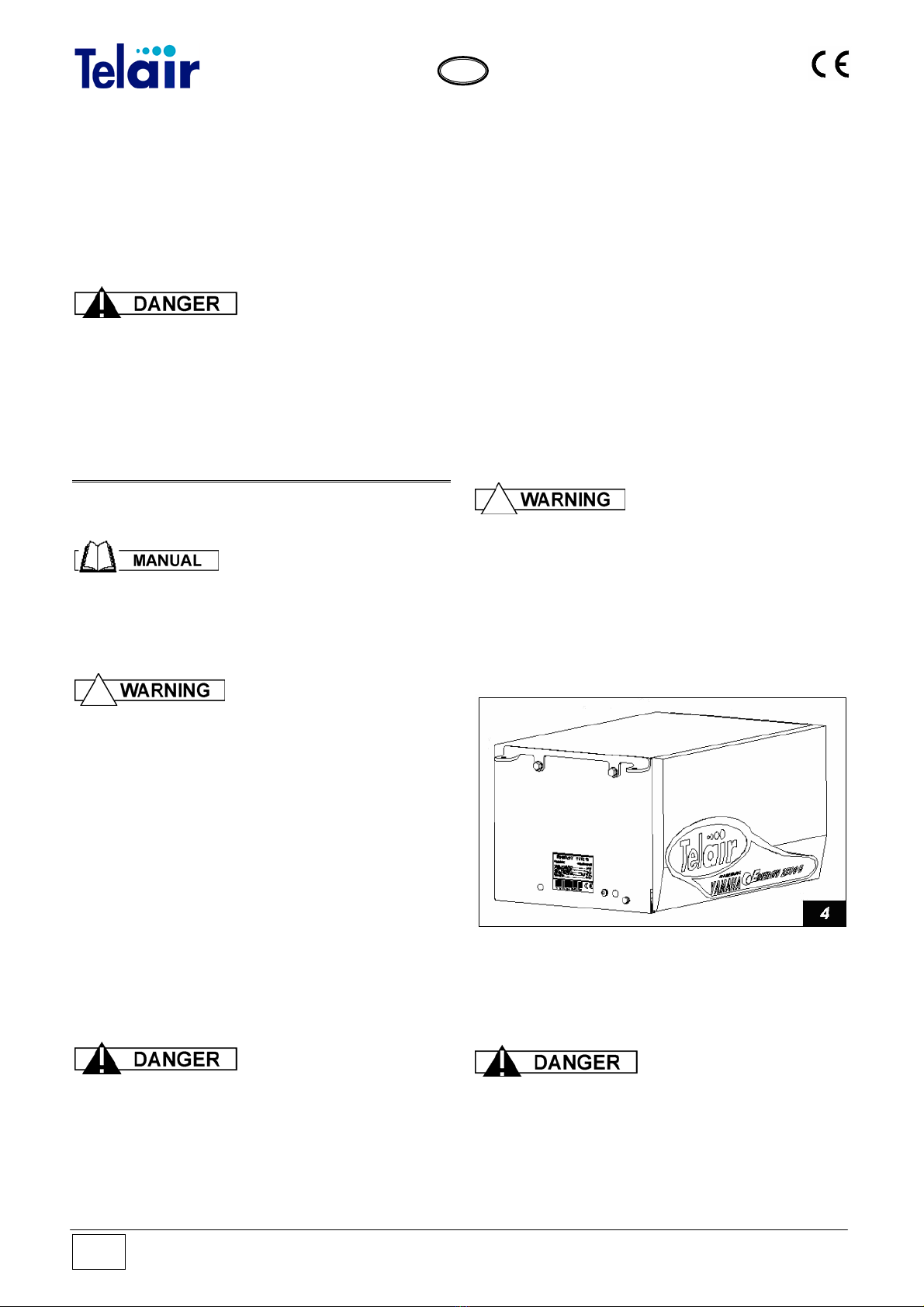
The ENERGY 4010B generating sets are
provided with anchoring brackets with extra
vibration dampers (Fig. 4, Ref. 1) and a fuel filter
to be fitted along the generator feeding pipe. The
brackets allow for hanging and floor assembly.
This kind of assembly provides the following
advantages: less room taken up, quick
installation, easy access for routine and
unscheduled maintenance.
Make sure that there is enough room around the
hood of the generating set to let cooling air
through; also leave 10 cm free room between the
hood and the surrounding parts.
Should the generating set air intake be behind a
wheel of the vehicle, care should be taken to
prevent water from being sprayed into the
generating set by the wheel when raining.
Ensure that, when the door
is open, the engine sliding surface can be
taken out (Fig. 12).
4.2.1 Hanging assembly
The generator, when sticking out of the package,
is preset for hanging assembly, as shown in fig.
12.
The package also contains 4 vibration-damping
cylinders (fig. 5 ref.1) and 2 brackets for hanging
assembly (fig. 5 ref. 2).
The vibration-damping
cylinders must imperatively be fitted as
shown in fig. 5. They must be pressed, and
NOT extended (as shown in fig. 6) by the
generator weight.

Vers. 001 Energy 4010 B
G
B
9
4.2.2 Floor fastening
The package contains a drilling jig, which allows
the generator bearing surface to be prepared
quickly, fig. 7.
Place a spongy, heat-
resistant gasket around the outlet opening of
the exhaust pipe. The gasket height must
reach the bottom of the generator and has the
purpose of preventing hot air from spreading
inside the generator compartment.
The brackets of the generator must be moved in
order to fasten the Energy 4010B on the bearing
surface.
On both sides, remove the hole plugs (fig. 8 ref.
1) and screw out the screws (fig. 8 ref. 2) in order
to remove the bracket (fig. 8 ref. 3).
Place the bracket (fig. 9 ref. 3) on the 4 holes
which were previously covered by the plugs
using the same screws (fig. 9 ref. 2) and apply
the hole plugs (fig. 9 ref. 1) in the seats which
previously housed the screws.

Energy 4010 B Vers. 001
G
B
10
The generator can now be located on the
previously drilled surface (fig.7) using the suitable
vibration-damping cylinders (fig. 10 ref. 1) and
spacers (fig. 10 rif.2)
4.3 Wiring connection instructions
By using the special key to open the lock,
remove the front door.
Then remove the bottom surface locking screws
(Fig. 11 Ref. 2) on both sides.
Take out the bottom surface with the engine all
the way to the mechanical stop (Fig. 12).
If you wish to completely remove the engine
surface, screw out the locking screws (Fig. 11
Ref. 3), too.
4.4 Battery connection
To start up the generating set, connection to the
battery of the vehicle must be provided using a
sheathed power cable up to current standards,
with the cross-section shown in Table 1.
To this end, the generating set is provided with
two special terminals (Fig.13 Ref.2) used to
connect the positive and negative poles of the
battery.
Connect the cable of the positive pole (red cable)
to the terminal already having a red cable and
the cable of the negative pole (black pole) to the
terminal already having a black cable. The cable
of the negative pole must be of the same cross-
section as the positive cable, and must be
connected both to the negative pole of the
battery and to the vehicle chassis.
Make sure there is good contact; remove any
paint or rust from the contact surface, and protect
the connection by applying grease.
The capacity of the battery to be used for starting
up must not be less than 100 A/h.
The soundproofing box is equipped with two
cable outlets used to let through the battery
connection cables (Fig. 11 Ref. 1).
The cable presser block is used to prevent water
seeping into the power generating set.

Vers. 001 Energy 4010 B
G
B
11
Always fit a 100 A fuse
onto the positive cable connecting the
generating set to the positive pole of the
battery.
4.5 Electric Load connection
To connect loads to the power generating set,
use a three-pole cable up to the applicable
standards in force. The correct cross section is
shown in Table 1. Table 1
Model Sect. mm2
line 230 V Cable leng.
Lgth < 6 m Cable leng
Lgth. > 6 m
4010B 4 10 16
LINE
CONNECTION 230 V BATTERY
CONNECTION
For connection to the 230V input line, the
generating set is equipped with a special terminal
strip (Fig.13 Ref.1) to which the cables must be
connected.
Use the special cable outlet (Fig.11 Ref.1) to
prevent water seeping into the generating set.
Although the generating set is equipped with a
special internal thermal cut-out to cut power
delivery in the event of overload or short circuits
(Fig.13 Ref.5), it is advisable to install (in the
vehicle control panel) a thermomagnetic cut-out
switch, suitably set to stop power delivery to the
various users when current absorption exceeds
16,5 Amp for ENERGY 4010 B
If the generating set thermal cut-out switch has
been operated, press the button (Fig. 7 Ref. 5) to
restore closed circuit and power delivery
conditions.
Carefully check the
position of the line connection for picking up
230 Volt current. Wrong connection could
damage the generating set irreparably or
create dangerous short circuits.
Energy 4010 B Vers. 001
G
B
12
4.6 Auxiliary electric cable connection
All 3 auxiliary cables to connect are equipped
with a polarized connector.
One cable is necessary for generator operation,
while the other 2 are optional cables.
•Cable from the generating set to the control
panel (mandatory). It is included in the
standard supply and is 5 metres long. Check
that its length is sufficient to cover the chosen
rout between the generating set and the
control panel. Optional cables in longer sizes
are also available.
After leading the cable through the cable
outlet block (Fig.11 Ref.1) connect the white
connector to the fixed connector (Fig.13 Ref.
9) provided inside the generating set,
checking that the plugging direction is correct.
•Cable from the generating set to the auxiliary
fuel pump and fuel tank reserve (optional).
From the three-pole connector (Fig.13 Ref.8)
it is possible to take two cables to supply
electric input to an auxiliary fuel pump; also
see paragraph 4.8.
From the same connector (Fig.13 Ref.8) it is
also possible to take the signal for tank fuel
warning; also see paragraph 4.10.
•Cable from the generating set to the auxiliary
battery charger (optional). From the bipolar
connector (Fig.13 Ref.6) it is possible to
derive supply for an RCB battery charge
regulator via two 4 mm2cables; also see
paragraph 4.11.1.
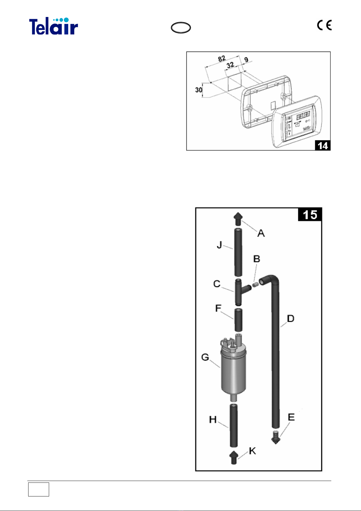
4.7 Electronic control panel connection
Choose your required position for the control
panel inside the vehicle and drill a 30 x 32 mm
rectangular hole. After letting out of the hole the
connecting cable coming from the generating set
(paragraph 4.6) connect the cable black
connector on the back of the electronic control
panel. Fix the electronic control panel (Fig.14) by
using 3 x 20 mm self-tapping screws, making
sure that the rear part does not interfere with
other surfaces. Apply light pressure to fix the
plastic frame, until the anchoring tabs click in.
4.8 Auxiliary (optional) fuel pump connection
If the distance that fuel must cover between the
fuel tank and the generating set is too long or the
tank is installed at a lower level than the
generating set, the fuel pump installed inside the
generating set may find it difficult to take fuel in
from the tank by suction. In this case, an auxiliary
optional fuel pump (code 00507) should be
installed as close as possible to the tank for easy
priming.

Vers. 001 Energy 4010 B
G
B
13
As is shown in the figure, fuel coming from a tank
K fitting is taken in by suction by the pump Gvia
a hose Hand then fed to the joint Cvia the hose
F.
The amount of fuel necessary for generating set
operation will be fed through the hose J to the
generator unit A; while any excess fuel will return
to the tank via the return fitting E.
Inside the joint C, a flow rate reducer B should be
installed consisting in a fit-in cylinder with a 2.5
mm ID. Each pipe coupling must be secured with
a special clamp.
On the generating set front is a three-pole
connector (Fig.13 Ref.8). Checking the wiring
diagram, identify the two auxiliary fuel pump
control poles (+12 and GND ). Two cables with
minimum cross sections of 1 sq.mm must be
connected to those two Faston terminals with
special connectors to reach the auxiliary pump
poles. (Fig.15 Ref. G)
4.9 (Optional) tank installation instructions
The fuel tank installation position (Fig. 10) must
be chosen so as to ensure that the fuel hose
length is reduced to a minimum.
Also ensure that the hose cross-section is not
reduced due to choking, bending or crushing. We
advise the install the tank at the same height as
the generating set; in any case, the installation
height difference should never exceed 20 cm
(Fig. 16).
Should it not be possible to observe the
maximum permitted level difference
requirements, an electric fuel pump can be
installed (available as an optional part, code
00507) which can easily overcome over 1 metre
level differences between the fuel tank and the
generating set.
See paragraph 4.8
Do not install the fuel
tank next to sources of heat; the tank should
be protected from the risk of outside water
seeping.
Carry out the fuel tank-to-generating set
connection by using a rubber hose (Fig.16 Ref.
2) suitable for unleaded fuel with an ID of 5 mm
interposing a fuel filter (Fig.16 Ref. 1).
The tank requires an outlet and a special hose is
connected to the special hose connector to this
end (Fig.16 Ref.3). Make sure that the outlet
hose path is upwards (Fig.16 Ref.4) and straight-
lined without any elbows.
Dealers can supply two different fuel tank models
to meet any installation requirements.
•For standard vehicle installation, use the
optional tank code 05472 (Fig.16 Ref.8) with a
capacity of 15 litres; the filler (Fig.16 Ref.5) is
supplied complete with a closing plug. (Fig.16
Ref. 6)
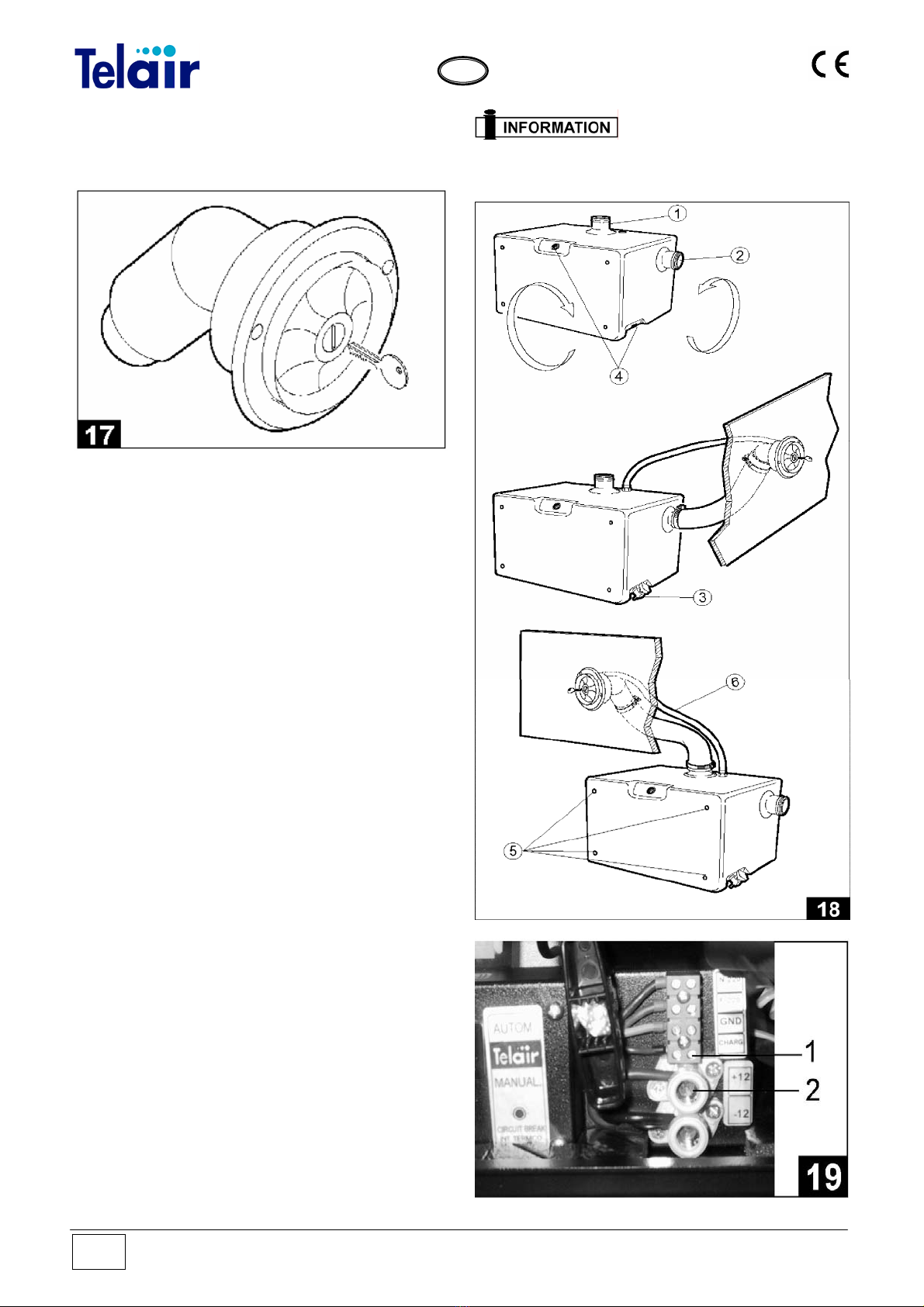
•The optional tank code 05466 (Fig. 18)
with a capacity of 15 litres has been designed for
installation at different positions to make the most
of the available vehicle space and to enable filler
(Fig. 17) connection at two different locations
(Fig.18 Ref. 1 and 2). This enables the installer to
choose the most suitable solution each time
according to the type of installation.
The fuel cut-off tap (Fig. 18 Ref. 3) can also be
screwed onto two different threaded pipe fittings
(Fig.18 Ref. 4) according to different installation
positions.
Energy 4010 B Vers. 001
G
B
14
For tank anchoring to the vehicle, special
threaded inserts (Fig.18 Ref. 5 ) and (Fig.16 Ref.
7) should be used according to requirements.
4.10 Fuel reserve
Both fuel tank models are provided with a tap
with fuel warning (Fig.18 Ref.3). To electrically
connect this component, ground the wire
screwed on the tap body then connect the other
tap wire to the special three-pole connector
Faston terminal via an electric lead (Fig.13 Ref.
8); to identify the correct Faston terminal, check
the wiring diagram.
The fuel reserve available in both tanks is
approximately 4 litres.
A special fuel warning light (Fig.30 Ref.8) will
light up to show that the fuel level inside the tank
has gone below the safe reserve level.
4.11 Battery charger
ENERGY 4010B generating sets are equipped
with a battery charger which can deliver current
of approximately 10 Amp at 12 V. It can be used
to recharge the generating set start-up battery.
To obtain this function, use a 2,5 mm2cross-
section cable to connect the terminal identified by
CHARG (Fig.19 Ref. 1) to the positive pole (red
cable) of the generating set (Fig. 19 Ref. 2)
possible to use the 12 Volt alternating current
output provided on the bipolar connector shown
in Fig. 13 Ref. 6 .
4.11.1 Auxiliary Battery Charger
If you wish to recharge a different battery or do
not wish to use the CHARG terminal, it is To
these two Faston terminals, 4 sq.mm cross-
section cables should be connected to obtain
interfacing to an optional RCB regulator (code
05424) as shown in Fig. 20.
The generating set will not
autonomously recharge the battery used for
starting-up unless this is connected to a
battery charger.

Energy 4010 B Vers. 022
15
G
B
The generating set will not
autonomously recharge the battery used for
starting-up unless this is connected to a
battery charger.
4.12 Connecting an additional silencer
To further reduce the generating set operating
noise, an (optional) additional silencer can be
installed externally.
The additional silencer kit code 03991 consists
of:
•A silencer code 01761 (Fig.21 Ref.1).
•Two metre long section of flexible steel tubing
code 00705 (Fig.21 Ref.2).
•Two connection fastening clamps code 01655
(Fig.21 Ref.3).
•Two rubber suspenders cod. 02,440 (Fig. 21
Ref 4).
To connect the silencer to the generating set, first
of all remove the door (Fig.22 Ref.2) by using the
special key (Fig.22 Ref.1) and the muffler guard
(Fig.22 Ref.3).

Energy 4010 B Vers. 001
G
B
16
Then put the hose code. 00,705 (Fig. 21 Ref 2)
Lock the output of the exhaust pipe with clamp
code. 01,655 (Fig. 21 Ref 3).
Attach the hose (Fig. 21 Ref 2) to the terminal
input side of the muffler (Fig. 21 Ref 1) using the
other band that came on (Fig. 21 Ref 3).
Install the muffler 01761 using the appropriate
rubber suspenders.
Do not use silencers not
supplied by TELAIR Silencers that have not
been specially sized may damage the motor.
4.13 Connecting an External Network Relay
An (optional) relay or change-over switch code
05423 (Fig.28) should be fitted to the vehicle
wiring system. Its purpose is to insulate the
generating set when the vehicle is connected to
an external electric input network.
Connect the relay (Fig.29) according to the
following instructions:
•Connect the two wires of the 230 V line of the
generating set to the PINS 1 - 3.
•Connect the user line to the PINS 7 - 9.
•Connect the outside line to the PINS 6 – 4.
•Jumper the PINS 4 – A.
•Jumper the PINS 6 – B.
•Connect all the grounding cables together
Electric connections to
the generating set should be carried out by
skilled electricians only.
5 OPERATING INSTRUCTIONS
The generating set is
delivered without engine oil.
Use detergent oil for multigrade 4-stroke
petrol engines, having SAE viscosity suitable
for the operating climate (see table and
detailed indications on the user and
maintenance manual of the engine).
ENERGY series generators consist of petrol
internal combustion engines connected to an
alternator that can produce both alternating and
direct electrical current. The generating sets are
assembled inside a steel plate casing, insulated
and sound-proofed using special sound
absorbing materials.
Fuel is fed to the internal combustion engine via
a pump fitted to the generating set as part of the
standard supply.
5.1 Machine safety
The generating sets come with perfectly sealed
casings, so there is no danger of contact with any
moving or high temperature parts or with live
cables.
The doors open with a lock and key. The keys
must not be left within the reach of children or
inexperienced persons.
The generating sets
must only and exclusively be used with their
doors shut.
Remove any flammable substance (for
example: petrol, paints, solvents, etc.) from
near the generating sets.

Vers. 001 Energy 4010 B
G
B
17
Make sure that any hot parts of the
generating sets are not in contact with any
flammable material.
Never fill up the fuel tank while the engine is
running.
Never touch the generating sets or the wiring
connections with wet hands.
Never replace the fuses or the cut-out
switches with others having higher
amperage.
Should any electrical part need checking, this
must only be done with the engine turned off
and by specialised personnel.
The generating sets have been built in
compliance with the safety standards listed in the
EEC statement of compliance.
6 USING THE GENERATING SET
6.1 Starting up the generating set
The generating sets are provided with an
electronic remote control panel which allows you
to perform starting up / turning off operations and
to check their running conditions.
The panel controls are:
1 ON/OFF switch
2 Display unit
3 High temperature indicator
4 Engine minimum oil level indicator
5 Startup failed
6 Generator running (flashing)
7 Engine oil change indicator
8 Fuel warning light
9 Display time changeover switch
10 Reset
Set the startup switch (Fig.30 Ref.1) to its “ON”
position. The message “WAIT” will be displayed
for 8 seconds. After this time, the electronic
control panel will start the first automatic
procedure for starting up the generating set. If
the engine starts up at the end of this phase, the
“generator running” indicator light (Fig.30 Ref.6)
will start to flash.
Should the engine not start up, this automatic
procedure will be repeated up to 4 times.
If, at the end of a complete cycle, the engine has
not yet started up, the “startup failed” indicator
(Fig.30 Ref.5) will light up to signify that the
generating set has failed to start up.
If the “startup failed” indicator (Fig.30 Ref.5) light
only stays lit, you can repeat the procedure
several times. If the generating set has not
started up after several attempts, contact the
manufacturer’s After-sales service. Should the
battery be flat, you can start the generating set
by hand, using the handle of the engine coil
winding (Fig.31 Ref.1) after setting the selector
switch to "ON" (Fig.31 Ref. 2) and the electronic
control panel to "ON". Once you have started up
the engine manually, put the selector switch back
to "0FF" (Fig.31 Ref. 2). The start-up battery
should never be disconnected, as there would be
no input to the electronic control panel which
would prevent the generating set from working.

Energy 4010 B Vers. 001
G
B
18
6.2 Turning the generating sets off
To stop the generating set, set the switch 1 to its
"OFF" position (Fig.31 Ref.1).
The generating set is
provided with an internal combustion engine,
therefore, the fuel used is highly flammable.
The exhaust gases are conveyed under the
casing; their temperature, inevitably, is quite
high, even though they are mixed with
cooling air.
Do not touch the casing areas near the
exhaust, and do not put your hands or any
objects inside the casing.
6.3 Information on not recommended uses
These generating sets
must be installed and used by qualified and
authorised personnel only, according to the
manufacturer’s instructions. These
generating sets must only and exclusively be
used to produce electrical power on vehicles
provided with an electrical system built to
standards and according to the quantity of
power delivered.
6.3 Useful tips
To make the best use of the generating sets,
remember that even minor overloads - if they last
long enough - will operate the thermal cut-out
switches (Fig.31 Ref.3).
During the running-in period, do not subject the
new engine to loads exceeding 70% of the rated
load, at least for the first 50 running hours.
6.5 Control and alarm functions (Fig. 30)
2 Display: when the generating set has started
up, the total running hours will be displayed.
Press the key provided below the control panel
display unit (Fig.30 Ref.9) to display the number
of generating set operation hours since the latest
engine oil change.
3 High temperature indicator: this warning light
will light up when the temperature of the
generating set goes over its safety value; the
engine will stop at the same time.
4 Engine oil minimum level indicator: this
warning light will light up to indicate that oil in the
engine has gone below the minimum level. A
safety system will kill the engine automatically to
prevent failures.
5 Engine startup failed: this warning light will
light up to indicate that the generating set has not
started up, after all four start-up attempts.
7 Change oil: this warning light will light up when
the engine has reached 100 running hours since
the latest oil change. Every time the oil is
changed, the After-sales service staff must reset
the timer to zero.
8 Fuel warning: this warning light will light up
when the fuel level inside the extra tank has gone
below its reserve level (about 4 litres)
9 Display time changeover switch: press this
switch to display the running hours since the
latest engine oil change.
10 Reset: When the display shows characters
without any apparent logic, the panel needs to be
reinitialised. Press the Reset key (Fig.30 Ref. 10)
and, holding it down, switch on the panel. When
4 zeroes (0000) are displayed, the panel has
been reinitialised.
6.6 Control panel alarm causes and resetting
During generating set use, alarm signals may be
displayed referring to engine oil checks. After

Vers. 001 Energy 4010 B
G
B
19
checking the engine oil, the control panel must
be reset in the following way:
Alarm: the red ‘service’ light is flashing.
Cause: 50 hours have elapsed since the latest
engine oil change and oil level should be
checked.
How to reset the alarm: press the partial
counter key (Fig.30 Ref.9) and while holding it
down, turn the panel on and release the push-
button when the unit has started up
Alarm: the red ‘service’ light is lit.
Cause: 100 hours have elapsed since the latest
engine oil change and engine oil should be
changed.
How to reset the alarm: turn on the panel and
wait for the generating set to start. Now press the
button hidden under the small hole in the bottom
left corner (Fig.30 Ref.10) and release it
immediately thereafter.
Wait a couple of minutes before turning the
generating set off.
In certain situations, the data contained in the
microprocessor inside the panel may be altered.
This may be because the battery is very low, or
because the cables used to connect the battery
to the set have too small cross-sections. Altered
processor data may prevent the generating set
from running. In order to restore the generating
set operating efficiency, proceed as follows:
Alarm: the display unit shows random
characters.
Cause: malfunctioning due to low voltage during
start-up (low battery, cable cross-section too
small). Reinitialise the panel.
How to reset the control panel: press the
button (Fig.30 Ref. 10) and while holding it down,
turn on the control panel. Only release the push-
button when 4 zeros (0000) are displayed. The
panel has been reinitialised.
6.7 Automatic Version (optional)
If you wish the start-up batteries to be recharged
automatically in the En 4010 B generating sets, it
is possible to install the ASP (optional) automatic
control panel (fig.32) instead of the manual
control panel.
The elements making it up are:
1 ON/OFF switch for the start-up and switch-off
function
2 Display
3 High temperature indicator
4 Minimum oil level indicator
5 Start-up failed indicator
6 Generator running indicator (flashing)
7 Maintenance request indicator
8 Fuel reserve indicator
9 Hour or voltmetric changeover switch button
10 Reset
11 Battery charged indicator
12 Automatic function indicator
13 AUTO/MAN switch for the automatic or
manual function
6.7 MANUAL operation
See section 7.3
6.9 AUTOMATIC operation
Turn the AUTO/MAN switch (Fig.32 Ref.13) to
the AUTO position and set the start-up switch
(Fig. 25 Ref. 1) to ON position.
The automatic function indicator (Fig.32 Ref.12)
will light up. If the battery which supplies the
generating set has a voltage of more than 11.5
Volts, the battery charged indicator (Fig.32 Ref.
11) will light up.
When the voltage at the ends of the 12V DC
terminals of the generating set is lower than 11.5
Volts, the battery charged light indicator (Fig.32
Ref.11) will go off and the generating set will
begin the start-up procedure (similar to that of the
manual operation).
During the operation in automatic mode, the
display (Fig.32 Ref.2) will show the total running
hours of the generating set. Press the hour or
voltmetric changeover switch button (Fig.32
Ref.9) to display the voltage at the ends of the
12V DC terminals, i.e. at the ends of the battery.

Energy 4010 B Vers. 001
G
B
20
When the battery is charged, and anyway after at
least 15 minutes’ running, the battery charged
hours indicator (Fig.32 Ref.11) will light up and
the electronic control panel will turn off the
generating set.
Setting the switch to the
automatic position after turning the control panel
on sets the generating set in stand-by mode and
does NOT activate the automatic function.
Remember that the time which is taken by
the generating set in automatic mode to
recharge the battery may vary according to
the battery status, the amount of connected
batteries and the season temperature.
Generally, the lower the temperature the less
the time required to charge the battery.
Applying any load higher
than the energy just then available in the
battery will prevent the generating set from
turning on due to insufficient voltage.
7 MAINTENANCE INSTRUCTIONS
Only use original spare
parts. Using poorer quality spare parts may
damage your generating set.
Routine checks and adjustments are of the
essence in preserving a high level of
performance. Routine maintenance also
ensures long generating set life.
Before performing any
check or maintenance operation on the
generating set, turn the selector switch (Fig.
31 Ref.2) to the position 1 “manual” in order
to avoid accidentally starting up the
generating set.
7.1 Service check list
See table at the bottom of page 25.
7.2 Maintenance not requiring specialised
personnel
To perform this kind of service, it will be
necessary to open the generating set door. The
following precautions must therefore be taken:
1 The generating set must not be in operation,
and all its parts must be cold
2 Let the generating set cool off.
3 Turn the selector switch to the position "ON"
(manual) (Fig.31 Ref.2)
N.B. Remember to switch the selector switch
to "OFF" (automatic) after completing the
required checks.
7.3 Checking the engine oil level
•Unscrew the engine oil filler cap and clean the
dipstick (Fig.33 Ref.1).
•Put the dipstick back in without screwing.
•Take the dipstick out again, and make sure
that the engine oil level is between the two
(min and max) notches. Should the oil level be
below the minimum notch, restore the oil level
using the recommended type of engine oil
(refer to the engine user and maintenance
manual).
•Put the dipstick and filler cap back on and
screw tightly.
Do not fill to exceed the
maximum level, as this could cause
malfunctioning of the fuel pump and hence of
the generating set.
All engine oil level
checking operations must be performed with
the generating set in a perfectly horizontal
position.
Table of contents
Other Telair Inverter manuals


