manuals.online logo
Brands
  1. Home
  2. •
  3. Brands
  4. •
  5. Telco Sensors
  6. •
  7. Accessories
  8. •
  9. Telco Sensors Space Scan Series User manual

Telco Sensors Space Scan Series User manual

SS02 - ANN-NNN - USER MANUAL
Space Scan Series
Photoelectric measurement light curtains
Website: www.telcosensors.com
Warning
V
1.26 Part Number: L40-0666220750
E-Mail: [email protected]
This product is not a safety system and must not be used as such.
It is not designed for personnel safety applications, and must not be used
as a stand alone personnel safety system.
January 2015
edition
Made in Denmark Telco A/S reserves the right to make changes without prior notice
Page 1 of 4
tel
!
EN
Product Data
Electrical Data
SST (Transmitter)
SSR (Receiver)
Supply voltage
18
—
30 V dc
Max. Voltage ripple
15 % (within supply range)
Current consumption
100 mA (RMS)
75
mA
Reverse polarity protected
Yes
Short circuit protected
Yes
Environmental Data
Light immunity @5º incidence
> 100.000 lux
Temperature, operation
-30 to + 60 ºC
Sealing class
IP 67
Marking
Available Models
Model
Beam spacing
Sensing Range
Transmitter
SST 01-10-xxx-xxx-05-H-1D1-0.5-J5 5 mm
10 mSST 01-10-xxx-xxx-10-H-1D1-0.5-J5 10 mm
SST 01-10-xxx-xxx-20-H-1D1-0.5-J5 20 mm
Receiver
SSR 02-10-xxx-xxx-05-H-ANN-NNN-0.5-J12 5 mm
0.5 m — 10 mSSR 02-10-xxx-xxx-10-H-ANN-NNN-0.5-J12 10 mm
SSR 02-10-xxx-xxx-20-H-ANN-NNN-0.5-J12 20 mm
Connection
Wiring Diagram ANN-NNN
5 pin, M12 8 pin, M12
SST 5 pole M12 male connecto
r
SSR 8
pole M12 male connecto
r
Wiring diagram
ANN-NNN
Installation & Adjustments
Installation
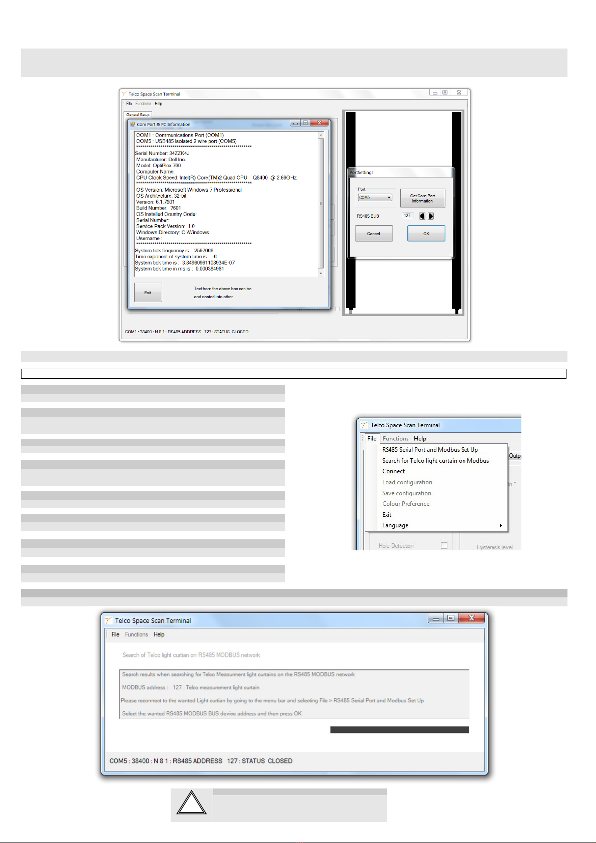
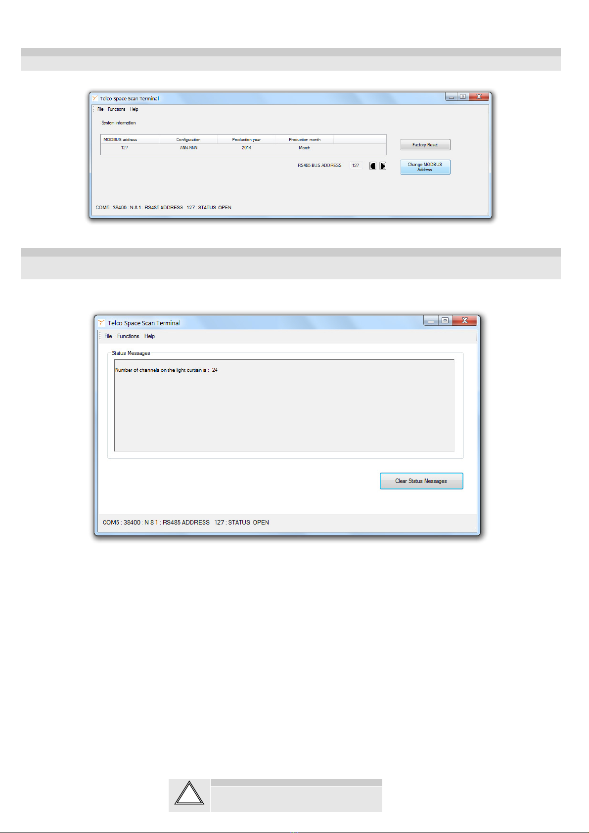
The light curtain is configured by the PC program ‘Telco Space Scan Terminal’, described in
the following pages. Before using it, check the power supply complies with electrical data.
1 Mount the transmitter (SST) and receiver (SSR) facing each other and correctly aligned.
2
Wire the sensor according to the wiring diagram.
Notice that the pin 2 on the SSR and the pin 3 on SST (blue wires) must be connected
together to a common GND ( — ).
Make sure the SSR output load does not exceed 100 mA.
3 Check for correct wiring before turning power on.
4 When the power on indicator (green LED) on SSR and SST is on, the system is
operating.
5 The position of the receiver and transmitter must not be changed after power-up. The
light curtain is only intended for static applications.
SST Test Input
The transmitter SST can be externally disabled and enabled via the black control wire for test
purposes. When the transmitter is disabled the action of the receiver corresponds to breaking
all beams.
Indicators
SSR Red LED Status indicator
SSR Yellow LED Detection Indicator
SSR & SST Green LED Power on indicator
Troubleshooting
Probable Reason
Corrective Action
1. Symptom: Status indicator (Red LED) on SSR is constant on.
SST has no power. Check supply and supply cable to the SST
SST & SSR white, grey and blue wires are
not connected correctly. Connect the wires.
2. Symptom: Output indicator (Yellow LED) on SSR is flashing.
Severe electrical interference. Separate SSR and SST supply cable from high
voltage cables.
Severe ambient light. Swap position of SSR and SST.
Cross talk from another light curtain or
photo sensor Swap position of SSR and SST.
Cross talk from a nearby HF strip light Swap position of SSR and SST or remove the
strip light.
3. Symptom: Digital outputs do not response when IR beams are obstructed.
One or more beams are blocked or the
rails are out of sensing range.
Remove obstruction or reduce the distance
between the rails.
The test input on SST is activated Remove SST pin 4 (black wire) from ground.
Outputs are not configured for simple
detection of obstructions
If needed factory reset the SSR using the
System Information page in the PC program
‘Telco Space Scan Terminal’
SSR02 and PC connection
To setup or adjust a SS02 it is required to use the Telco Space Scan Terminal software together with an RS485 data link.
Transmitter Model Black wire
connected to ( - )
Black wire
not connected
Black wire
connected to ( + )
SST 01-10-xxx-xxx-xx-H-1D1-0.5-J5 not transmitting transmitting transmitting
SS02 - ANN-NNN - USER MANUAL
Space Scan Series
Photoelectric measurement light curtains
Website: www.telcosensors.com
Warning
V
1.26 Part Number: L40-0666220750
E-Mail: [email protected]
This product is not a safety system and must not be used as such.
It is not designed for personnel safety applications, and must not be used
as a stand alone personnel safety system.
January 2015
edition
Made in Denmark Telco A/S reserves the right to make changes without prior notice
Page 2 of 4
tel
!
EN
1. Start by selecting the RS485 Serial Port and Modbus Set Up and select the correct port to communicate with the SS02. If the port number is not known it is possible to press the Get
Com Port Information. This will list all COM Ports used by the PC. (Full Com port details in Win7, WinXP only basic details are shown ). The RS485 BUS ADDRESS is default 127, but
address can be changed in the menu Function -> System Information.
2. Next press Connect and wait a few seconds before the connection is active.
File menu
RS485 Serial Port and Modbus Setup:
See SSR02 and PC connection.
Search for Telco light curtains on a Modbus.
Used for finding and identifying the Modbus address(es) of one or more light curtains on the
Modbus. For more info see below.
Connect
See SSR02 and PC connection.
Load configuration
Used to load a file that will configure all functions of the light curtain in one go. The information
is stored in a previously saved configuration file in ASCII format.
Save configuration
Saves information about the current configuration of the light curtain.
Colour Preference
It is possible to set up to 7 different colours for the beams on the screen.
Exit
Exit and close the program
Language
Language selection
File -> Search for Telco Light curtain on a Modbus
Use this function to find the Modbus Address(es) of Telco Light curtains on a Modbus, if the address(es) are unknown.
SS02 - ANN-NNN - USER MANUAL
Space Scan Series
Photoelectric measurement light curtains
Website: www.telcosensors.com
Warning
V
1.26 Part Number: L40-0666220750
E-Mail: [email protected]
This product is not a safety system and must not be used as such.
It is not designed for personnel safety applications, and must not be used
as a stand alone personnel safety system.
January 2015
edition
Made in Denmark Telco A/S reserves the right to make changes without prior notice
Page 3 of 4
tel
!
EN
Functions menu
Overview:
For configuration and basic settings of the light curtains.
System Information:
For basic system information and configuration of Modbus address.
Status Messages:
Status messages are logged and displayed by choosing this menu item.
Each functions associated with each of these menu items will be described in detail the
following.
Functions -> Overview -> General Setup tab
General Setup:
Right side shows the light curtain and the beam pattern. Unbroken or made beams are indicated by green and broken beams by red. The light curtain is in the setup oriented with the cable entry in the
bottom.
Scan Mode. Parallel or Cross beam selection.
On cross beam mode, the number of actual beams are increased from N straight beams to (3*N)-2 beams giving a more dense beam pattern, with larger detection certainty.
If objects are positioned in the centre, or close to the centre, between transmitter and receiver the measurement resolution is increased to the double, i.e. the crossed beam mode adds an additional
virtual beam between each of the straight beams, in total N-1 extra virtual beams. When crossed beam mode is selected the number of beams is increased to (2*N)-1 in total, which therefore also will
be the new maximum of the analogue output. Be aware that objects has to be taken out of the light curtain when switching from parallel beam mode into crossed beam mode when it is in automatic gain
mode. The reason is that the gain of the crossed beams has to be initialised.
Gain Control:
In the Manual Gain it is possible to set the Manual Gain Level (a fixed gain level). In Automatic Gain mode it is possible to set the excess gain level. In both manual and automatic gain is it possible
to set the Hysteresis level. Keep objects out of the light curtain when switching to automatic gain mode or when adjusting the excess gain level, because the initial setting of each beam requires
information about signal strength for an unbroken beam.
Blanking:
It means to deactivate beams resulting one or more areas in the light curtain where the status of the beams are ignored. Blanking can either be setup by writing directly which beams to be blanked in
the text box. Writing ’12-16, 20’ means that all beams starting from beam no 12 and ending with beam no.16, and beam no. 20 are blanked. When the blanking is written, it shall be transferred to the
light curtain pressing the button Write to Light Curtain, whereby it becomes active. Blanked beams are marked blue as seen below.
Beams can also be blanked by simply reading obstructed beams from the light curtain by pressing the button Measure From Light Curtain, whereby the obstructed and now blanked beams will be
written in the text box. It is not necessary to press Write to Light Curtain for activating the blanking.
Smoothing Function (Minimum Size of Coherent Area):
The Smoothing Function tells the SSR to ignore objects which are smaller than a specific size. If the Smoothing Function is set to 3, any object that interrupts 3 or less adjacent beams will be ignored.
Smoothing can be used, e.g., to ignore interference caused by wood chips while sawing a log.
The effect is obtained by a pre-processing of the beams status where all groups of adjacent broken beams with less than or equal to 3 beams are substituted by made beams.
This smoothing function is carried out after the ‘hole detection’ pre-processing.
Signal OK indicator: when the signal level is sufficient for stable operation of the light curtain the Signal OK indicator will be green. If the Signal OK indicator is off, the gain should be increased or
distance between transmitter and receiver should be decreased. The Signal OK indicator will also go out if there is a loss of synchronisation between the SST02 and the SSR02.
SS02 - ANN-NNN - USER MANUAL
Space Scan Series
Photoelectric measurement light curtains
Website: www.telcosensors.com
Warning
V
1.26 Part Number: L40-0666220750
E-Mail: [email protected]
This product is not a safety system and must not be used as such.
It is not designed for personnel safety applications, and must not be used
as a stand alone personnel safety system.
January 2015
edition
Made in Denmark Telco A/S reserves the right to make changes without prior notice
Page 4 of 4
tel
!
EN
Functions -> System information
System information contains the information displayed in the figure below. The MODBUS address can be modified using the Change MODBUS Address button.
Functions -> Status Messages
Selecting Functions -> Status messages makes the window below appears. Status messages and error messages are logged and displayed. The log can be cleared by pressing the button Clear
Status Messages.

This manual suits for next models

1

Other Telco Sensors Accessories manuals

Telco Sensors SM 3000/CAT2 Series User manual

Telco Sensors

Telco Sensors SM 3000/CAT2 Series User manual

Telco Sensors SpaceMaster Series User manual

Telco Sensors

Telco Sensors SpaceMaster Series User manual

Telco Sensors Space Guard Series User manual

Telco Sensors

Telco Sensors Space Guard Series User manual

Telco Sensors SpaceMaster Series User manual

Telco Sensors

Telco Sensors SpaceMaster Series User manual

Telco Sensors SpaceMaster Series User manual

Telco Sensors

Telco Sensors SpaceMaster Series User manual

Telco Sensors SpaceMaster Series User manual

Telco Sensors

Telco Sensors SpaceMaster Series User manual

Popular Accessories manuals by other brands

Robern VDELECTRIC installation instructions

Robern

Robern VDELECTRIC installation instructions

System Sensor SENS-RDR quick start guide

System Sensor

System Sensor SENS-RDR quick start guide

Julabo FT200 operating manual

Julabo

Julabo FT200 operating manual

Banner World-Beam QS18 Series instruction manual

Banner

Banner World-Beam QS18 Series instruction manual

Datalogic IO-Link S100 Series instruction manual

Datalogic

Datalogic IO-Link S100 Series instruction manual

Shel lab SMI2 Installation and operation manual

Shel lab

Shel lab SMI2 Installation and operation manual

Andersen VeriLock manual

Andersen

Andersen VeriLock manual

DOUXE S3 Active Stylus Pen instruction manual

DOUXE

DOUXE S3 Active Stylus Pen instruction manual

ASTRO DEVICES Nexus DSC Pro Quick setup guide

ASTRO DEVICES

ASTRO DEVICES Nexus DSC Pro Quick setup guide

Comcast Visonic MCT-340 SMA Battery Installation

Comcast

Comcast Visonic MCT-340 SMA Battery Installation

Abibird AbiSensor quick start guide

Abibird

Abibird AbiSensor quick start guide

Kampa Rally instructions

Kampa

Kampa Rally instructions

IWO 12000mAh user manual

IWO

IWO 12000mAh user manual

ROSE DISPLAYS GOTCHA WITH V CLIP instruction sheet

ROSE DISPLAYS

ROSE DISPLAYS GOTCHA WITH V CLIP instruction sheet

Omega Engineering Venue 7 3736 China Only instruction sheet

Omega Engineering

Omega Engineering Venue 7 3736 China Only instruction sheet

Bitspower Griffin 120 Fan instruction manual

Bitspower

Bitspower Griffin 120 Fan instruction manual

Philips CPWBS154 Quick start quide

Philips

Philips CPWBS154 Quick start quide

TIS MS-PIR-CM installation manual

TIS

TIS MS-PIR-CM installation manual

manuals.online logo
manuals.online logoBrands
  • About & Mission
  • Contact us
  • Privacy Policy
  • Terms and Conditions

Copyright 2025 Manuals.Online. All Rights Reserved.