Telco Sensors SpaceMaster Series User manual
SM 9000-IO USER MANUAL
SpaceMaster Series
Photoelectric DC thru beam sensors
Website: www.telcosensors.com
Warning
V.1.3 Part Number: L40-0666220955
E-Mail: info@telcosensors.com
This device is not to be used for Personnel Protection in Machine
Guarding Safety applications. This device does not include the self-
checking redundant circuitry necessary to allow its use in personnel
machine guarding stand-alone safety applications.
June 2022 edition
Made in Denmark
Telco A/S reserves the right to make changes without prior notice
Tel
EN
!
Product Data
Electrical Data
Transmitter
Receiver
Supply Voltage
10-30 V dc
Voltage ripple
+/– 15%
Reverse polarity protected
Yes
Short circuit protected
-
Yes
Power consumption
Max. 40 mA
Max. Output load
-
100 mA
Environmental Data
Temperature, operation
-20 to +60 ºC
Sealing class
IP 69K
Approvals
Available Models
Model Output Sensing Range
Transmitter SMT 9020C-IO IO-Link 1 -20 m, adjustable
SMT 9070C-IO IO-Link 1 -70 m, adjustable
Receiver
SMR 9420-IO IO-Link/NPN 20 m
SMR 9520-IO IO-Link/PNP 20 m
SMR 9470-IO IO-Link/NPN 70 m
SMR 9570-IO IO-Link/PNP 70 m
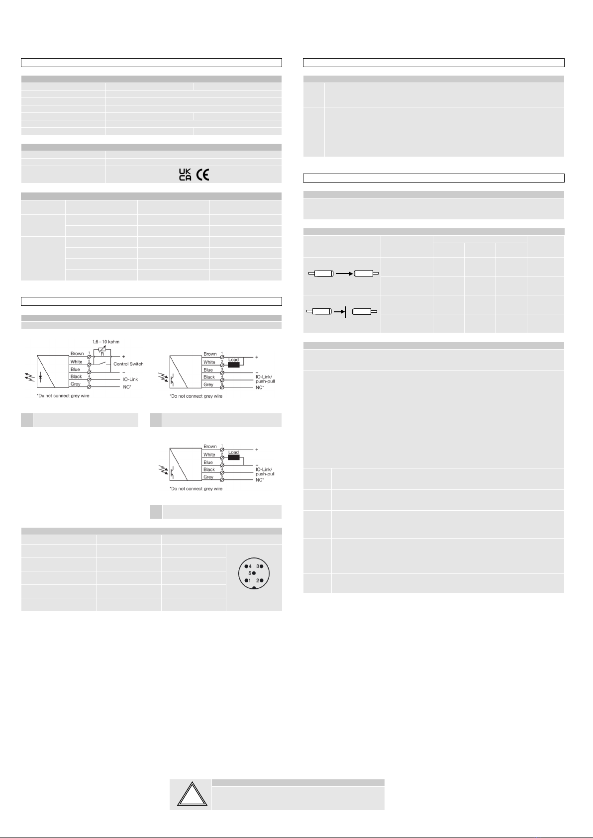
Connection
Wiring Diagrams
Transmitter
Receivers
SMT 90X0C-IO
Variable range & test input setup
SMR 94X0-IO
Transistor NPN
SMR 95X0-IO
Transistor PNP
Connection Wires/Pins
Cable
5 pin, M12 plug, male
Supply + Brown Pin 1
Sensor plug
Supply – Blue Pin 3
Control /output White Pin 2
IO-link Black Pin 4
Not connected Gray Pin 5
Mounting & Alignment
Mounting & Alignment
1 Mount the transmitter and receiver sensors facing each other. Make sure the distance
between the sensors does not exceed the specified sensing range of the system.
2
Align the sensors by moving, either the transmitter or receiver sensor, horizontally and
vertically making sure they are pointing at each other until the output is:
- Deactivated when no object is present. (Dark operated)
- Activated when no object is present. (Light operated)
3 Fasten the transmitter and receiver sensors securely.
Avoid acute angles on cable close to sensor.
Adjustments
General
The transmitter power and 4 different channels can be selected. The channel is selected via
IO-Link and must be the same on corresponding transmitter and receiver. The transmitter
power is selected either with the white wire or with IO-Link. The power can be from 0 to 100 %.
Output Logic
Detection Output Mode
Output status
Yellow
LED
IO-link /
C/Q
PNP NPN
Object absent
Dark operated
(N.O) Low Open Closed Off
Light operated
(N.C.) High Closed Open On
Object present
Dark operated
(N.O) High Closed Open On
Light operated
(N.C.) Low Open Closed Off
Transmitter Power Adjustment SMT 9020C-IO / SMT 9070C-IO
Maximum transmitting power can be used for most applications. Maximum transmitter power
(factory set) is advised for applications with contaminated environments.
The transmitting power can be adjusted externally via the ‘White’ control wire of the transmitter
SMT unit. The transmitter level can be adjusted using a resistor (e.g. potentiometer) of 1.6k to
10K ohm or a voltage source of 0.5 – 2.0 V dc connected respectively between the ‘White’
control wire and – (negative) ‘Blue’ supply wires. Adjustment of transmitter SMT power may be
required in applications where objects to be detected are small or translucent.
Furthermore, the transmitting power can be adjusted via IO-link, under the parameter tab,
using the ‘Power value’ parameter and the ‘Power input’ parameter. From the factory, the
‘Power input’ will be set as ‘Cable’, i.e. the transmitting power is adjusted externally. To control
the power via IO-link, change ‘Power input’ to ‘IO-link’, and adjust the ‘power value’ parameter.
Proceed with the following steps:
1 Set transmitter power to maximum. The default setting is using the wire and it
should be 10K ohm or greater.
2 Select target object with the smallest dimensions and most translucent surface.
3
Place target object between transmitter and receiver sensors. If the output status
changes, adjustment is not required. If the output status has not changed proceed
to step 3.
4
Decrease the transmitter power (by reducing the resistance or lowering the ‘Power
value’) until the output status changes. If the output status has not changed, attempt
to move the sensors further apart or angle one of the sensors, and then repeat
procedure.
5 Remove target object. Observe the output status has changed.
Transmitter
Receiver
Transmitter
Receiver

SM 9000-IO USER MANUAL
SpaceMaster Series
Photoelectric DC thru beam sensors
Website: www.telcosensors.com
Warning
V.1.3 Part Number: L40-0666220955
E-Mail: info@telcosensors.com
This device is not to be used for Personnel Protection in Machine
Guarding Safety applications. This device does not include the self-
checking redundant circuitry necessary to allow its use in personnel
machine guarding stand-alone safety applications.
June 2022 edition
Made in Denmark
Telco A/S reserves the right to make changes without prior notice
Tel
EN
!
PC connection
To setup or adjust a SMT/R, it is required to use TMG IO-Link Device Tool together with TMG-USB IO-Link Master, or another IO-Link PC application with its USB-adaptor.
How to connect
Connect the TMG-USB IO-Link Master USB-adaptor to the USB-port of the PC and to the cable of the SMT/R.
Download the IO-Link Device Tool software and the SMT/R-IODD file from the Telco Sensors website in https://www.telcosensors.com/downloads, selecting Software in Document type section.
Install the TMG IO-Link Device Tool V5.1.1-5122 SE – Setup file and run the program.
Import the SMT/R-IODD by selecting “Import IODD” in the Options menu, if not already done in a previous session.
Click on “Search Master” and select the Master in the popup window.
Click on “Go Online” .
Click on “Check Devices” .
Click on “Takeover devices into engineering” to the SMT/R device.
Double click on the row with the SMT/R, to open the Device menus.
Click on “Upload from Device”to upload the SMT/R settings.
For more information see TMG’s User Manual for the IO-Link Device Tool.
Popup windows:
!

SM 9000-IO USER MANUAL
SpaceMaster Series
Photoelectric DC thru beam sensors
Website: www.telcosensors.com
Warning
V.1.3 Part Number: L40-0666220955
E-Mail: info@telcosensors.com
This device is not to be used for Personnel Protection in Machine
Guarding Safety applications. This device does not include the self-
checking redundant circuitry necessary to allow its use in personnel
machine guarding stand-alone safety applications.
June 2022 edition
Made in Denmark
Telco A/S reserves the right to make changes without prior notice
Tel
EN
!
Parameters
On the Parameter tab, you can set up all the parameters of the sensor.
Parameters SMT:
Parameters SMR:
Standard Command - Restore Factory Settings
Restores all user-settings to default values.
Channel
SM 9000 can run in 4 different channels. The same channel should be selected for matching SMT and SMR.
Power input
Select between Cable and IO-Link to control the power of the SMT 9000.
Power value
Select a value for how much power the SMT 9000 should send with. From 0 to 100 %
Light Operated
Select between true or false.
Changing the selection will invert the outputs.
On delay
Select delay on output when going from object absent to object present. Can be set from 0.1 to 600.0 seconds.
Off delay
Select delay on output when going from object present to object absent. Can be set from 0.1 to 600.0 seconds.
Oneshot time
Select how long time the outputs will be active when going from object absent to object present. Can be set from 0.1 to 600.0 seconds.
Forced output
Select if the output should be forced to the value in Forced value.
Forced value
Select the output state if the Forced output is true.

SM 9000-IO USER MANUAL
SpaceMaster Series
Photoelectric DC thru beam sensors
Website: www.telcosensors.com
Warning
V.1.3 Part Number: L40-0666220955
E-Mail: info@telcosensors.com
This device is not to be used for Personnel Protection in Machine
Guarding Safety applications. This device does not include the self-
checking redundant circuitry necessary to allow its use in personnel
machine guarding stand-alone safety applications.
June 2022 edition
Made in Denmark
Telco A/S reserves the right to make changes without prior notice
Tel
EN
!
Process Data
Power
Shows the transmitters power setting from 0 to 100%
Output
Shows the state of the receiver output. It follows the state of the yellow led.
Identification
On the Identification tab, you will see the information about the sensor

SM 9000-IO USER MANUAL
SpaceMaster Series
Photoelectric DC thru beam sensors
Website: www.telcosensors.com
Warning
V.1.3 Part Number: L40-0666220955
E-Mail: info@telcosensors.com
This device is not to be used for Personnel Protection in Machine
Guarding Safety applications. This device does not include the self-
checking redundant circuitry necessary to allow its use in personnel
machine guarding stand-alone safety applications.
June 2022 edition
Made in Denmark
Telco A/S reserves the right to make changes without prior notice
Tel
EN
!
Diagnosis
Device Status
“Device is OK” will show at the “Device Status” under normal operation.
“Failure” will show in the SMT menu if it has a failure on the light emitting diode.
“Maintenance required” will show in the SMR menu if it has a “Signal Alarm”. This happens if the signal has less than 40% excess gain for more than 3 seconds.
This manual suits for next models
7
Table of contents
Other Telco Sensors Accessories manuals

Telco Sensors
Telco Sensors SpaceMaster Series User manual

Telco Sensors
Telco Sensors SM 3000/CAT2 Series User manual

Telco Sensors
Telco Sensors SpaceMaster Series User manual

Telco Sensors
Telco Sensors SpaceMaster Series User manual

Telco Sensors
Telco Sensors Space Scan Series User manual

Telco Sensors
Telco Sensors Space Guard Series User manual
Popular Accessories manuals by other brands


Rechner Sensors
Rechner Sensors KAS Series Application note

Chad Valley
Chad Valley Giant Wavy Slide Assembly & user instructions

daviteq
daviteq WS433-M12F-ATE user guide

Active Tools
Active Tools 2k rowing shoe Installation use & care instructions

UCS
UCS 40450K user manual

ring
ring BT88LP000CH000 quick start guide