Telco Sensors SM 3000/CAT2 Series User manual
USER MANUAL, original instructions
SpaceMaster SM 3000/CAT2 Series
Photoelectric DC thru beam sensors
Website: www.telcosensors.com
Part Number: 0666220667
E-Mail: info@telcosensors.com
May 2020 edition
Made in Denmark
Telco A/S reserves the right to make changes without prior notice
tel
Product Data
Electrical Data
Transmitter
Receiver
Supply Voltage
10-30 V dc
Voltage ripple
15% (within supply range)
Reverse polarity protected
Yes
Short circuit protected
-
Yes
Inductive load protected
-
Yes
Current consumption
Max. 30 mA
Max. 8 mA
Max. output load
-
100 mA
Environmental Data
Temperature, operation
-20 to +50 ºC
Light immunity @ 0Oincidence
20.000 lux
Sealing class
IP 67
Approvals
Available Models
Model
Output
Output Mode
Sensing Range
Transmitter SMT 3010C/CAT2 - -
10 m
Receiver
SMR 3010/CAT2 NPN
Light operated
(N.C.)
SMR 3210/CAT2 PNP
Light operated
(N.C.)
General Instructions and Precautions
This light curtain can be used in industrial, commercial and garage doors and gates, as
described in EN 12453, when it is used as device type E according to clause 5.5.1.
Even though the sensor has a high degree of immunity to ambient light sources, it is
recommended to avoid direct exposure to sunlight, and interference from flashlights or other
infrared light sources, such as other photo sensors.
If the front cover of the sensor becomes contaminated, it has to be cleaned with a slightly
damp cloth. Do not use organic solvents or detergents. If the light curtain is very contaminated,
the output may go into safe state and de-energize even after the cleaning, due to safety
reasons.
Ensure that the sensor is mounted, so that it is mechanically stable during operation.
Severe rain and snow may be detected due to the high sensitivity of the light curtain.
Connection
Wiring Diagrams
SMT 3000 Variable range and test input
SMR 3010 Transistor NPN
SMR 3210 Transistor PNP
Connection Wires
Supply +
Brown
Supply -
Blue
Control/Output
Black
Mounting & Alignment
Mounting & Alignment
1 Mount the transmitter and receiver sensors facing each other. Make sure the distance
between the sensors does not exceed the specified sensing range of the system.
2
Align the sensors by turning, either the transmitter or receiver sensor, horizontally and
vertically until the output is:
- Deactivated when no object is present. (Dark operated)
- Activated when no object is present. (Light operated)
3 Fasten the transmitter and receiver sensors securely.
Avoid acute angles on cable close to sensor.
Adjustments
Output Logic
Detection
Output Mode
Output status
Yellow LED
Object absent
Light operated (N.C.) Closed On
Object present
Light operated (N.C.) Open Off
Transmitter power adjustment
The transmitting power can be adjusted externally via the wires of the transmitter sensor.
Adjust using a resistor (e.g. a potentiometer) of 200 ohm to 10k ohm or a voltage source of 1-
4 V dc connected respectively between control and – supply (ground) wires. Adjustment of the
transmitter power may be required in applications where objects to be detected are small or
translucent. Proceed with the following steps:
1 Select target object with the smallest dimension and most translucent surface.
2
Place target object between transmitter and receiver sensors. If the output is activated,
adjustment is not required. If the output is not activated proceed to step 3.
3
Decrease the transmitter power (by decreasing the resistance) until the output is
activated.
4 Remove target object. Observe the output deactivates.
Note: If the test input is not to be used (not safety application), it is recommended to connect the
control wire to + (positive) supply wire.
Indicator LEDs
Indicator LEDs
Green LED on transmitter Power on indicator
Yellow LED on receiver Indicates closed output
Troubleshooting
Troubleshooting
Probable Reason
Corrective Action
1. Symptom: Power indicator (Green LED) on SMT is off.
No power supply
Check supply and cable to the SGT
2. Symptom: Output indicator (Yellow LED) on SMR does not correspond to a beam break
No power supply to SMR
Check supply and cable to the SMR
TX is not emitting, green LED off
Check supply and cable to the SMT
SMT is disabled
Enable the SMT
The sensors are misaligned
Align the sensors
3. Symptom: Output indicator (Yellow LED) on SMR is flickering
Severe electrical interference
Remove SMR and SMT supply cable from high
voltage cables
Severe ambient light
Change position of SMT and SMR
Cross talk from another light transmitter
Change position of SMT and SMR
SMR Output Response Time
SMR Output Response Time (typical)
Range Ton (beam break) Toff (beam make)
2 m
14 ms
10 ms
4 m
12 ms
11 ms
6 m
11 ms
15 ms
8 m
8 ms
29 ms
10 m
8 ms
34 ms
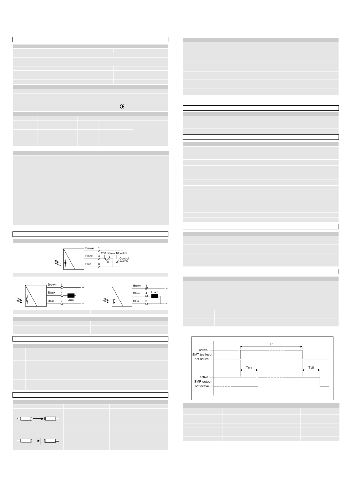
SMT Test Input
SMT Test Input
If the sensor is used as a safety device in accordance with EN12978, the function of the
sensor pair has to be tested periodically, at the latest at one of the end positions of the
door leaf. (EN12978:2003+A1:2009: 4.4.3).
During the test the transmitter is disabled by connecting the control wire to – supply
(ground). The control system has to check that the receiver de-energises the output (NC
system). The control wire of the transmitter is hereafter disconnected or connected to +,
and it is checked that the receiver re-energises the output.
Enable transmitter Open (off) control switch, a resistor over 10k ohm, or voltage over 4 V dc
Disable transmitter
Close (on) control switch, a resistor below 200 ohm, or voltage below 0,7 V dc
Note: If the test input is not to be used (not safety application), it is recommended to connect the
control wire to + (positive) supply wire.
SMT test input reaction time (typical)
Range Ton (beam break) Toff (beam make) Tr (min.)
2 m
14 ms
10 ms
20 ms
4 m
12 ms
11 ms
18 ms
6 m
11 ms
15 ms
17 ms
8 m
8 ms
29 ms
14 ms
10 m
8 ms
34 ms
14 ms
Transmitter
Receiver
Transmitter
Receiver

USER MANUAL, original instructions
SpaceMaster SM 3000/CAT2 Series
Photoelectric DC thru beam sensors
Website: www.telcosensors.com
Part Number: 0666220667
E-Mail: info@telcosensors.com
May 2020 edition
Made in Denmark
Telco A/S reserves the right to make changes without prior notice
tel
EU Declaration of conformity
Declaration of Conformity to:
Directive 2006/42/EC of the European Parliament and of the Council, Annex I, relating to
machinery and subsequent amendments.
Directive 2004/108/EC of the European Parliament and of the Council, relating to
electromagnetic compatibility.
The conformity is declared according to:
EN61000-4-2, EN61000-4-3, EN61000-4-4, EN61000-4-6, EN55011 A2, EN 60947-5-2,
EN12978:2003+A1:2009, IEC 61496-2:1997 + FDIS 2005, EN ISO 13849-1:2015
EC type examination by
TüV Nord,
Langemarckstr. 20, 45141 Essen, Germany
Number of EC-examination: 44 205 13099405
Manufacturer
Telco A/S, Nørregade 10C, 1. Sal, 4600 Køge, Denmark
Managing director Steen Andreasen.
Signature:
Køge 8/6-2020:
Authorised representative
This manual suits for next models
3
Other Telco Sensors Accessories manuals

Telco Sensors
Telco Sensors SpaceMaster Series User manual

Telco Sensors
Telco Sensors SpaceMaster Series User manual

Telco Sensors
Telco Sensors SpaceMaster Series User manual

Telco Sensors
Telco Sensors Space Scan Series User manual

Telco Sensors
Telco Sensors Space Guard Series User manual

Telco Sensors
Telco Sensors SpaceMaster Series User manual
Popular Accessories manuals by other brands


Rechner Sensors
Rechner Sensors KAS Series Application note

Chad Valley
Chad Valley Giant Wavy Slide Assembly & user instructions

daviteq
daviteq WS433-M12F-ATE user guide

Active Tools
Active Tools 2k rowing shoe Installation use & care instructions

UCS
UCS 40450K user manual

ring
ring BT88LP000CH000 quick start guide