Extreme Networks NG300 User manual

Extreme Networks, Inc.
3585 Monroe Street
Santa Clara, California 95051
(888) 257-3000
(408) 579-2800
http://www.extremenetworks.com
Sentriant NG Installation Guide
Published: January 2008
Part number: 100288-00 Rev. 01

Sentriant NG Installation Guide2
AccessAdapt, Alpine, Altitude, BlackDiamond, EPICenter, ESRP, Ethernet Everywhere, Extreme Enabled, Extreme
Ethernet Everywhere, Extreme Networks, Extreme Standby Router Protocol, Extreme Turbodrive, Extreme Velocity,
ExtremeWare, ExtremeWorks, Essentials, ExtremeXOS, the Go Purple Extreme Solution, ScreenPlay, Sentriant,
ServiceWatch, Summit, SummitStack, Triumph, Unified Access Architecture, Unified Access RF Manager, UniStack,
the Extreme Networks logo, the Alpine logo, the BlackDiamond logo, the Extreme Turbodrive logo, the Summit
logos, the Powered by ExtremeXOS logo, and the Color Purple, among others, are trademarks or registered
trademarks of Extreme Networks, Inc. or its subsidiaries in the United States and/or other countries.
Adobe, Flash, and Macromedia are registered trademarks of Adobe Systems Incorporated in the U.S. and/or other
countries. AutoCell is a trademark of AutoCell. Avaya is a trademark of Avaya, Inc. Internet Explorer is a registered
trademark of Microsoft Corporation. Mozilla Firefox is a registered trademark of the Mozilla Foundation. sFlow is a
registered trademark of sFlow.org. Solaris and Java are trademarks of Sun Microsystems, Inc. in the U.S. and other
countries.
Specifications are subject to change without notice.
All other registered trademarks, trademarks, and service marks are property of their respective owners.
© 2007-2008 Extreme Networks, Inc. All Rights Reserved.

Table of Contents
Sentriant NG Installation Guide 3
Preface........................................................................................................................................... 5
About this Guide .........................................................................................................................5
Organization of this Guide............................................................................................................5
Conventions................................................................................................................................5
Related Publications ...................................................................................................................6
Chapter 1: About the Sentriant NG Appliance .................................................................................... 7
Chassis Overview.........................................................................................................................7
Front Panel Features ...................................................................................................................7
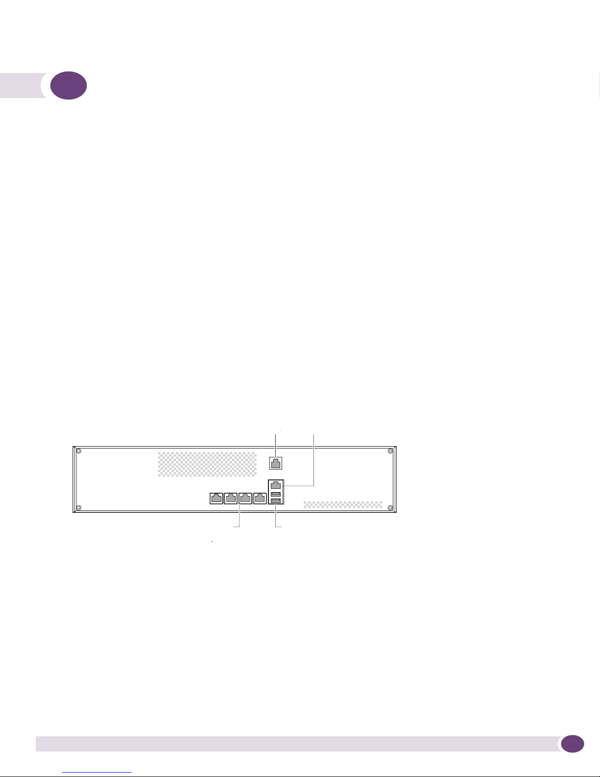
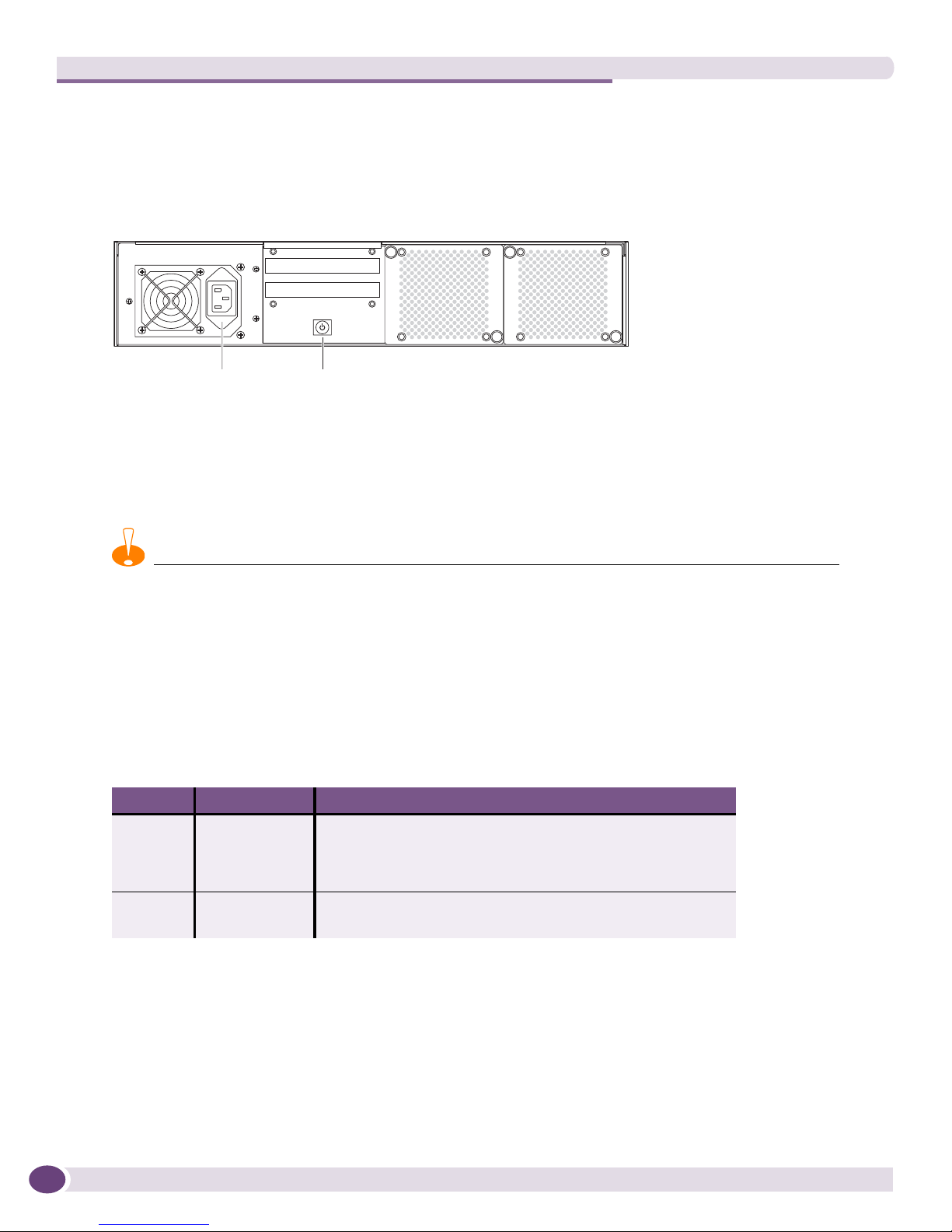
Back Panel Features....................................................................................................................8
LED Operation ............................................................................................................................8
Chapter 2: Site Preparation and Unpacking ...................................................................................... 9
Site Requirements for the Sentriant NG Appliance .........................................................................9
Rack Ventilation Requirements...............................................................................................9
Unpacking the Sentriant NG Appliance .......................................................................................10
Package Contents................................................................................................................10
Chapter 3: Installing the Sentriant NG Appliance............................................................................. 11
Overview ..................................................................................................................................11
Required Tools and Equipment...................................................................................................12
Attaching the Mounting Brackets ................................................................................................12
Installing the Sentriant NG Appliance in a Rack...........................................................................13
Connecting Power .....................................................................................................................13
Connecting Cables ....................................................................................................................14
Configuring the Switch ..............................................................................................................14
Chapter 4: Start-Up and Initial Configuration...................................................................................17
Requirements Before the Initial Setup.........................................................................................17
Initial Configuration Using the Serial Port....................................................................................17
Navigating in the Text User Interface ....................................................................................18
Power-On and System Boot ..................................................................................................18
Installing the Sentriant NG Manager Software ..............................................................................23
Starting and Logging In To Sentriant NG Manager ..................................................................23
Using the Online Help System ..............................................................................................24
Appendix A: Safety Information ...................................................................................................... 25
Considerations Before Installing .................................................................................................25
Power Safety ............................................................................................................................25
Maintenance Safety...................................................................................................................26
General Safety Precautions ........................................................................................................26
Battery Replacement and Disposal..............................................................................................27
Table of Contents

Table of Contents
Sentriant NG Installation Guide4
Appendix B: Technical Specifications ............................................................................................31
Specifications...........................................................................................................................31
FCC Class A Notice ...................................................................................................................33
User Information .................................................................................................................33
ICES-003 Class A Notice ...........................................................................................................34
Index............................................................................................................................................ 35

Sentriant NG Installation Guide 5
Preface
This preface provides an overview of this guide, describes guide conventions, and lists other
publications that might be useful.
About this Guide
The Sentriant NG Installation Guide describes how to install and connect the Sentriant NG appliance and
perform required initial configuration.
This guide is intended for use by system and network administrators and by trained, qualified network
installation and support technicians who are responsible for installing and setting up network
equipment. This guide assumes a working knowledge of:
●Ethernet technology and terminology as it applies to local area network (LAN) access
●Safety practices when working with electrical equipment.
Organization of this Guide
This guide includes the following chapters and appendixes:
●Chapter 1, “About the Sentriant NG Appliance”
●Chapter 2, “Site Preparation and Unpacking”
●Chapter 3, “Installing the Sentriant NG Appliance”
●Chapter 4, “Start-Up and Initial Configuration”
●Appendix A, “Safety Information”
●Appendix B, “Technical Specifications”
Conventions
Table 1 and Table 2 list conventions used in Extreme Networks customer documentation.
Table 1: Notice Icons
Icon Notice Type Alerts you to...
Note Important information, helpful suggestions, or reference material.
Caution Risk of personal injury, system damage, or loss of data.
Warning Risk of severe personal injury.

Preface
Sentriant NG Installation Guide6
Related Publications
For more information about configuring and using the Sentriant NG appliance, refer to the following
publications:
●
Sentriant NG Operation Console User Guide
●
Sentriant NG Manager User Guide
●
Sentriant Rules Guide
Documentation for Extreme Networks products is available from the Extreme Networks website at the
following location:
http://www.extremenetworks.com/services/documentation
Table 2: Text Conventions
Convention Description
Screen displays or
entered text
This typeface represents information as it appears on the screen, command syntax,
or text you enter on a command line.
The words “enter”
and “type”
When you see the word “enter” in this guide, you must type something, and then
press the Return or Enter key. Do not press the Return or Enter key when an
instruction simply says “type.”
<Key> names Key names appear in text in one of two ways:
• Referenced by their labels, such as “the Return key” or “the Escape key”
• Written with angle brackets, such as <Enter> or <Esc>
If you must press two or more keys simultaneously, the key names are linked with a
plus sign (+). Example:
Press <Ctrl> + <Alt> +< Del>.
Words in italicized type Italics emphasize a point of information or denote new terms at the place where
they are defined in the text.
Bold type Graphical user interface (GUI) names and control options that appear on the
management screen.

Sentriant NG Installation Guide 7
1About the Sentriant NG Appliance
This chapter includes the following sections:
●Chassis Overview on page 7
●Front Panel Features on page 7
●Back Panel Features on page 8
●LED Operation on page 8
Chassis Overview
The Sentriant NG appliance is a compact enclosure that is 2 RU (3.5 inches) high. It fits into a standard
19-inch (48.26 cm) rack. The Sentriant NG appliance provides four Gigabit Ethernet
detection/mitigation ports, a Gigabit Ethernet management port, a console port, and two USB ports.
Front Panel Features
Figure 1 shows the front panel of the Sentriant NG appliance.
Figure 1: Front Panel Features
The front panel of the Sentriant NG appliance has the following ports:
●Ethernet management port—Connects the Sentriant NG appliance through an Ethernet cable to the
I/O port of a switch. Use this port to manage the Sentriant NG appliance. Detection and mitigation
of threats are not performed on the management port.
●Serial console port—Connects the Sentriant NG appliance to a terminal. Use this port to perform
initial configuration and maintenance of the Sentriant NG appliance. Connect this port using the
provided DB-9F-to-RJ-45 cable.
●10/100/1000 Base-T Ethernet detection/mitigation ports—Connect these ports to the switch ports
that will be monitored by the Sentriant NG appliance.
●USB ports—Used for technical support only. Do not insert any device into these ports unless
instructed by an Extreme Networks technician.
NG300_front
USB ports
Ethernet
management port
Serial port
Detection/Mitigation
ports
Detection/mitigation
ports
Serial console
port

About the Sentriant NG Appliance
Sentriant NG Installation Guide8
Back Panel Features
Figure 2 shows the back panel of the Sentriant NG appliance.
Figure 2: Back Panel Features
The back panel of the Sentriant NG appliance has the following features:
●AC power connector
●Power switch
CAUTION
After the Sentriant NG appliance is powered on, do NOT shut down the unit by pressing the power switch. Shutting
down the unit should be done only through Sentriant NG Manager. See the Sentriant NG User Guide for details.
LED Operation
The detection/mitigation ports and the Ethernet management port have integrated link and activity
LEDs to indicate operating status. Table 1 describes the LED meanings.
Table 1: LED Meanings
LED Type Activity Meaning
Link
(Left)
Steady green A 1000-Mbps link is detected and connected.
(Because the Ethernet management port operates at 10/100
Mbps only, it should never show a green link.)
Steady amber A 100-Mbps link is detected and connected.
Activity
(Right)
Steady green No activity
Blinking green Activity
NG300_back
Power
switch
AC power
connector

Sentriant NG Installation Guide 9
2Site Preparation and Unpacking
This chapter includes the following sections:
●Site Requirements for the Sentriant NG Appliance on page 9
●Unpacking the Sentriant NG Appliance on page 10
Site Requirements for the Sentriant NG Appliance
The Sentriant NG appliance can be rack-mounted in a standard 19-inch rack.
Be sure to locate the system away from heat sources and in an area that provides unobstructed air flow
to the chassis cooling vents. The chassis intake ambient air temperature should not exceed 95 ºF (35 ºC)
or drop below 41ºF (5º C).
CAUTION
Do not place a monitor or other object on top of the system. The mounting brackets and chassis cover are not
designed to support additional weight.
Make sure that the voltage and frequency of the power source matches the electrical ratings of the
Sentriant NG appliance, and that the building and/or power source provides overload protection.
In regions that are susceptible to electrical storms, we recommend that you plug your system into a
surge suppressor.
Rack Ventilation Requirements
●Make sure that there is a minimum of 3 inches of airspace at the back of the chassis.
●Open-type racks should meet the manufacturer’s recommended ventilation requirements.
●Enclosed-type racks should have a louvered front and back with a fan to dissipate heat generated by
equipment mounted in the rack.
●If you are installing the Sentriant NG appliance in enclosed racks with top-mounted ventilation fans,
make sure that there is adequate ventilation for the racks. Heat generated by equipment mounted in
the bottom of the rack can be drawn up into equipment mounted in the top of the rack.
●Chassis intake ambient air temperature should not exceed 95º F (35º C).
●Operating humidity should be kept between 10% and 95% relative humidity (noncondensing).

Site Preparation and Unpacking
Sentriant NG Installation Guide10
Unpacking the Sentriant NG Appliance
Do not unpack the Sentriant NG appliance until you are ready to install it. Storing the chassis in its
shipping container helps protect it from accidental damage.
Package Contents
When you unpack the shipping container, confirm that you received the following items:
●Extreme Networks Sentriant NG appliance
●Bracket mounting kit:
■Screws, #6-32 x 1/4-inch (qty. 8)
■L-shaped mounting brackets (qty. 2)
●AC power cord for use in North America
●DB-9F to RJ-45 console cable
●CD containing
■Sentriant NG Manager Installer for Windows
■XML files for IPTel rules
■XML file of Names Sets exclusions
■Sentriant NG Manager Installer for MAC OS (unsupported)
■Sentriant NG Installation Guide
■
Sentriant NG Manager User Guide
■
Sentriant Rules Guide
●CD containing
■Sentriant NG Operations Console installer for Windows
■
Sentriant NG Operation Console Users Guide
●
Sentriant NG Appliance Quick Start Guide
●Software License Agreement
●Registration card

Sentriant NG Installation Guide 11
3Installing the Sentriant NG Appliance
This chapter includes the following sections:
●Overview on page 11
●Required Tools and Equipment on page 12
●Attaching the Mounting Brackets on page 12
●Installing the Sentriant NG Appliance in a Rack on page 13
●Connecting Power on page 13
●Connecting Cables on page 14
●Configuring the Switch on page 14
Overview
The Sentriant NG appliance fits into a standard 19-inch (48.26 cm) rack.
Carefully read all cautions and warnings before beginning the installation.
CAUTION
The Sentriant weighs approximately 40 pounds (18 kilograms). To reduce the risk of personal injury, do not attempt
to install the system in a rack by yourself.
CAUTION
The Sentriant rack installation procedures should be performed by trained service technicians.
CAUTION
Do not place a monitor or other object on top of the Sentriant chassis. The chassis bracket hardware is not designed
to support the additional weight of objects other than the Sentriant chassis.
WARNING!
If you are installing more than one Sentriant in a rack, always install the first Sentriant in the lowest available
position in the rack. Installing a Sentriant in a high position in the rack first could cause the rack to tip over.

Installing the Sentriant NG Appliance
Sentriant NG Installation Guide12
Required Tools and Equipment
You need the following items to install the Sentriant NG appliance:
●Mounting bracket kit (provided with the Sentriant NG appliance):
■Eight #6-32 x 1/4-inch Phillips screws
■Two rack-mounting brackets
●Phillips screwdriver to attach the mounting brackets
●Rack mounting hardware appropriate to your equipment rack
●Screwdriver appropriate for the mounting hardware used with your equipment rack
NOTE
Rack-mounting hardware is not included with the Sentriant NG appliance. Use mounting screws appropriate to your
equipment rack.
Attaching the Mounting Brackets
To attach the mounting brackets:
1Place a mounting bracket along one side of the Sentriant NG appliance and align it with the
mounting holes in the chassis.
2Insert and tighten the provided
#6-32 x 1/4-inch screws to secure the bracket to the Sentriant NG
appliance.
3
Attach the other
bracket to the opposite side of the Sentriant NG appliance in the same manner.
Figure 3: Attaching the Mounting Brackets to the Chassis
B
A
install_front_bracket12_07
A. Mounting bracket
B. #6-32 x 1/4-inch screws

Sentriant NG Installation Guide 13
Installing the Sentriant NG Appliance in a Rack
CAUTION
The Sentriant NG appliance weighs approximately 40 pounds (18 kilograms). Lifting the Sentriant NG appliance and
attaching it to the rack is a two-person job.
To install the Sentriant NG appliance in a rack:
1Determine the mounting location for the Sentriant NG appliance.
2Position the Sentriant NG appliance at the mounting location and secure the mounting brackets to
both front posts using screws appropriate to the rack.
Figure 4: Securing the Sentriant NG Appliance to the Rack
Connecting Power
Connect the AC power cable from the power connector on the back of the Sentriant to an active power
outlet.
Refer to “Initial Configuration Using the Serial Port” on page 17 for instructions on how to bring the
Sentriant online.
attach_front_post12_07

Installing the Sentriant NG Appliance
Sentriant NG Installation Guide14
Connecting Cables
Connect cables to the Sentriant NG appliance as follows:
●Serial port connection
Connect the provided serial cable from the serial port on the of the Sentriant NG appliance to a
DB-9 serial port on a workstation.
●Management port
Connect a Category 5 or equivalent UTP cable from the management port on the Sentriant NG
appliance to an available 10/100/1000BASE-T I/O port on an Extreme Networks I/O module or
switch.
●Detection/mitigation port
Connect two category 5 or equivalent UTP cables from detection/mitigation ports 1 and 2 on the
Sentriant NG appliance to two open 10/100/1000BASE-T I/O ports on an Extreme Networks switch.
NOTE
Only one detection/mitigation port is needed for a default configuration. Use the additional detection/mitigation ports
if more than one VLAN is configured.
Configuring the Switch
Configure the switch as follows:
1Configure the switch port connected to detection/mitigation port 1 to be a mirror port.
2Configure the switch port connected to detection/mitigation port 2 to be a member of the VLAN
that will be monitored for threats. This VLAN should be 802.1q tagged.
3Configure the switch to mirror the threat detection VLAN.

Sentriant NG Installation Guide 15

Installing the Sentriant NG Appliance
Sentriant NG Installation Guide16

Sentriant NG Installation Guide 17
4Start-Up and Initial Configuration
This chapter includes the following sections:
●Requirements Before the Initial Setup on page 17
●Initial Configuration Using the Serial Port on page 17
●Installing the Sentriant NG Manager Software on page 23.
Requirements Before the Initial Setup
You must configure a read-only port and a VLAN read-write port on the Extreme Networks switch
before performing the initial setup of the Sentriant NG appliance. The read-write port must be mirrored
to the read-only port. The VLAN read-write port must be tagged to all VLANs being protected by the
Sentriant NG appliance.
To configure these ports, use the following CLI commands:
enable mirroring to port <ReadOnly_port> tagged
configure mirroring add port <ReadWrite_port>
configure vlan <vlan> add ports <ReadWrite_port> tagged
On BlackDiamond 8800 series switches and Summit X450a series switches, the CLEAR-Flow policy file
must be configured for all VLANs protected by the Sentriant NG appliance.
To configure the CLEARflow policy file, use the following CLI commands:
configure access-list <policy_file> vlan <vlan_name>
enable clear-flow
Initial Configuration Using the Serial Port
You must perform the initial configuration of the Sentriant NG appliance using the serial port
connection on the front of the appliance. After initial configuration, you can manage the system
remotely using the Sentriant Console Manager.
You can use any standard VT100
style terminal program such as Microsoft Windows HyperTerminal to
establish communications. When the connection to the Sentriant NG appliance is established, the
Sentriant text user interface guides you through the initial configuration procedure.
Configure the VT100 terminal program with the following settings:
●Baud rate = 38.4 Kbps
●Data bits = 8
●Parity = none
●Stop bits = 1
●Flow control = none
Follow the instructions in “Power-On and System Boot” on page 18 to establish a local connection.

Start-Up and Initial Configuration
Sentriant NG Installation Guide18
Navigating in the Text User Interface
Use the tab keys, the arrow keys, and the spacebar to navigate between fields or to select a command
option in a configuration screen.
Press [Enter] to execute a command option.
NOTE
The screen shots that illustrate the initial configuration sequence are intended as examples only. Actual content may
vary depending on system and network requirements.
Power-On and System Boot
Follow the instructions on the screen to perform the initial configuration.
1Power up the Sentriant NG appliance by pressing the power switch at the back of the unit.
The Sentriant text user interface displays a series of boot status messages on the local terminal that is
attached to the serial port.
After system boot is complete, the initial login prompt is displayed.
2At the initial login prompt, type admin and press [Enter].
NOTE
If you are performing a software upgrade or have Sentriant NG Manager previously installed on the Sentriant, you
will be asked to enter a password. A command line opens with the following message: To start the Text User
Interface, type tui.sh and press [Enter].

Sentriant NG Installation Guide 19
The Extreme Networks Sentriant Welcome screen is displayed.
3Use the tab key to select <Next> and
press
[Enter] to continue.
4The Extreme Networks End User License Agreement is displayed. Read the entire license agreement.
If you agree, select <Accept>
and press
[Enter] to continue.

Start-Up and Initial Configuration
Sentriant NG Installation Guide20
5The Host IP Configuration screen is displayed.
When you configure the IP address for a Sentriant NG appliance, this address is assigned as the
management IP address. Workstations running Sentriant NG Manager will use this address to
connect to the Sentriant NG appliance.
Enter the Hostname of the
Sentriant NG
appliance, its IP address, Net Mask, Gateway, and the
Management Interface. For example:
Hostname | Buld3522
IP Address | 192.168.21.88
Net Mask | 255.255.255.0
Gateway | 192.168.21.1
Management Interface | eth0
Select <Next> and press [Enter] to continue.
6The Password screen is displayed.
Other manuals for NG300
1
This manual suits for next models
1
Table of contents
Other Extreme Networks Network Accessories manuals

Extreme Networks
Extreme Networks PoS User manual

Extreme Networks
Extreme Networks Mogul-100 User manual

Extreme Networks
Extreme Networks Altitude 300-2 Manual

Extreme Networks
Extreme Networks GBX User manual

Extreme Networks
Extreme Networks Mini-GBIC Installation and operation manual

Extreme Networks
Extreme Networks Sentriant AG200 User manual

Extreme Networks
Extreme Networks Sentriant AG200 User manual

Extreme Networks
Extreme Networks Auto Configuration Quick guide

Extreme Networks
Extreme Networks Altitude 300-2 User manual

Extreme Networks
Extreme Networks GBIC Installation and operation manual