9
1
ON
B2B1
2
++
P1
6 5 4 3
8K2
6 5 4 3
4- GREEN
5- BROWN
6- WHITE
3 4 5 6
BK2
Green
Brown
White
3 4 5 6
BK2
Green
Brown
White
3. PRELIMINARY CHECK AND INITIAL START-UP
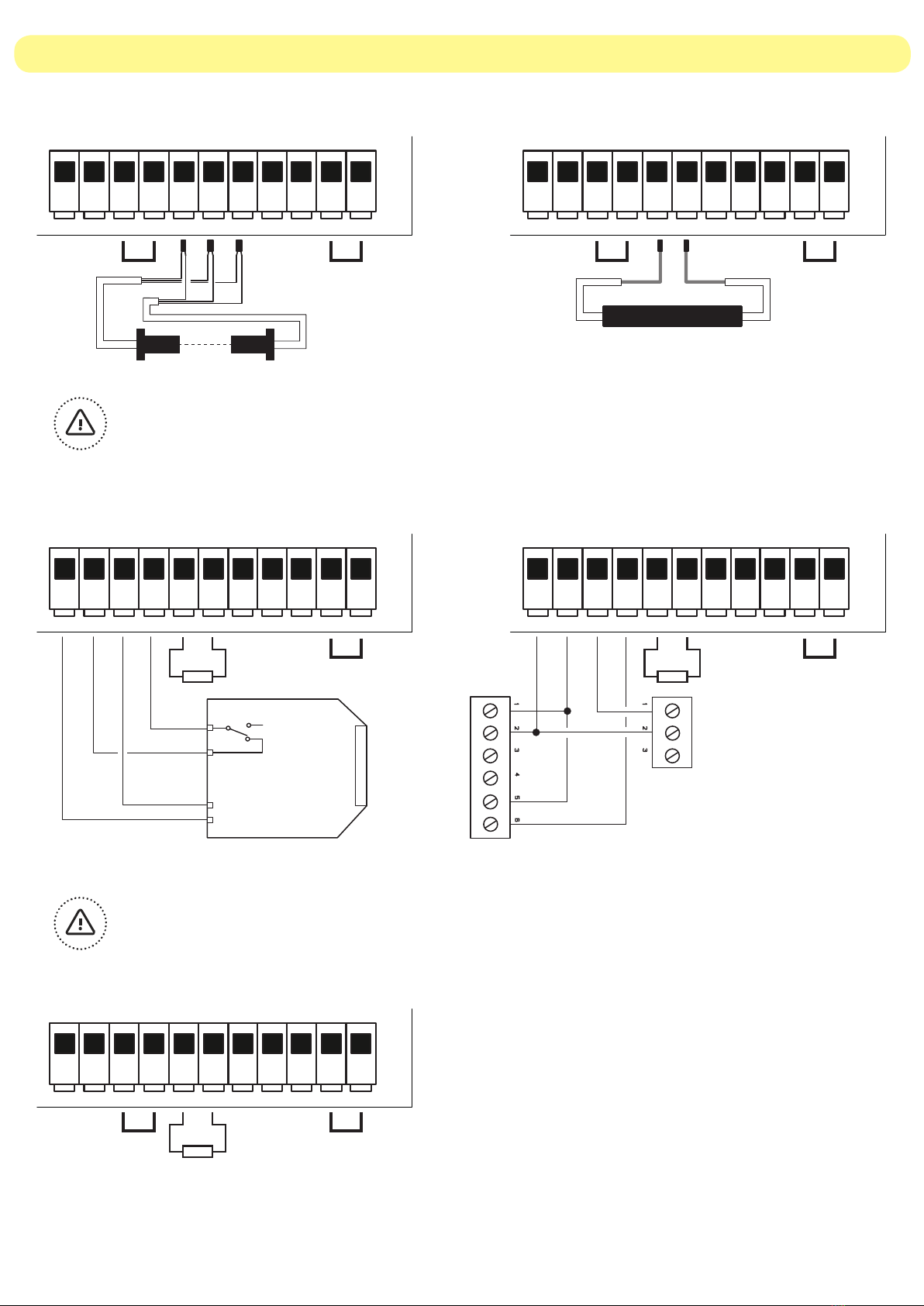
A proper connection box should be used to set the limit switch before wiring the motor in the control unit.
• Step 1: motor limit switch setting
Once the limit switches are set connect the motor to control unit and start the system up.
The buzzer emits 3 quick sounds if the memory is empty or 1 long sound if the memory has radio codes in.
• Step 2: motor connection and powering the board up
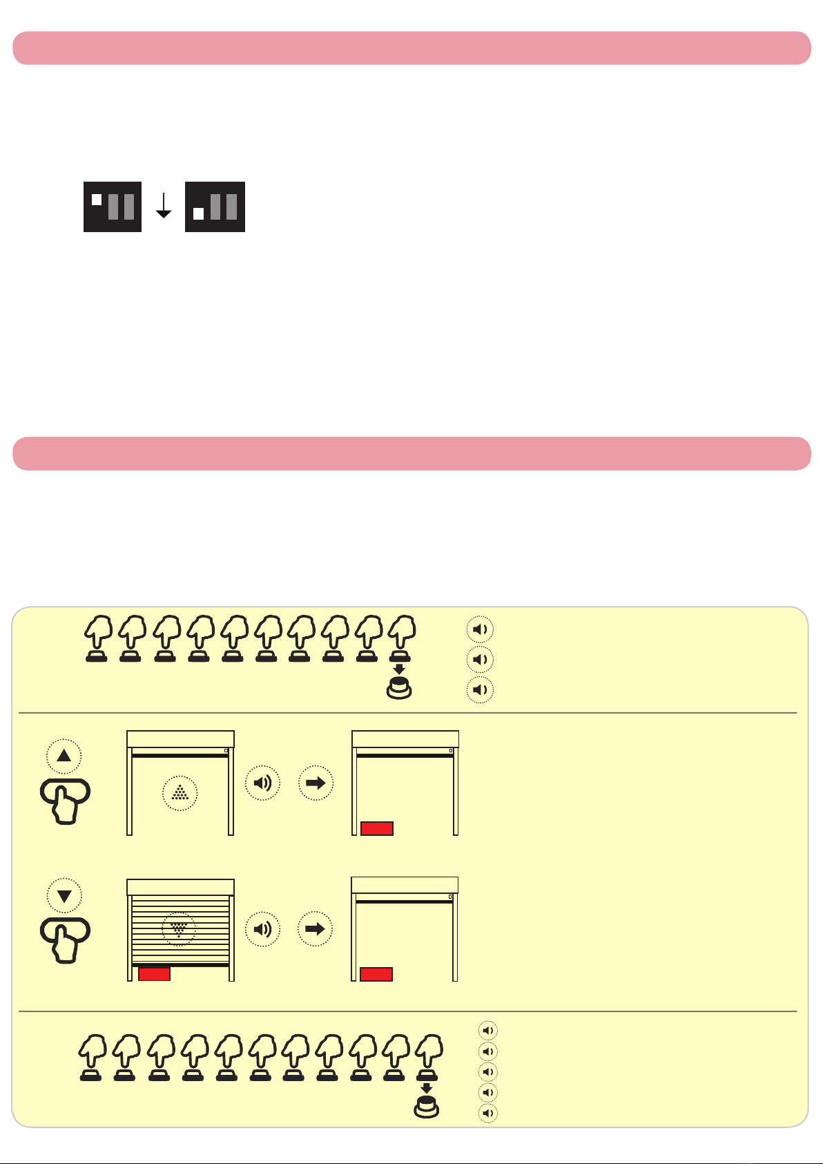
After the power-on, the control unit executes only opening commands until the door is fully opened.
Check the direction of the door; if the door is travelling in the wrong direction:
1- STOP the manoeuvre
2- Switch the control unit off
3- Swap BLACK and BROWN motor wires over - terminals 5 & 7
4- Power the board up again
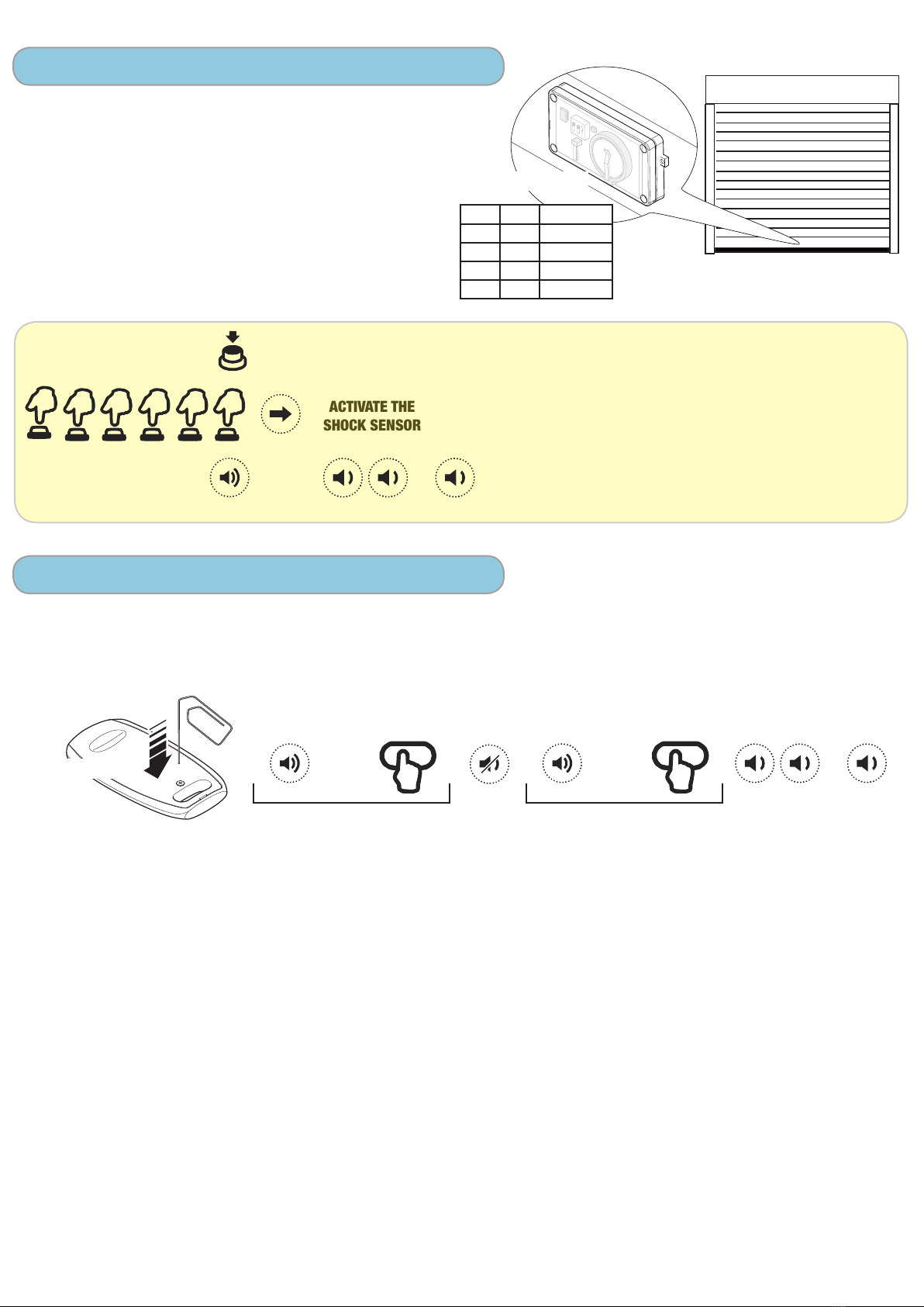
• Step 4: other safety devices and possible errors during the initial start-up
Check that the bottom slat transmitter (SLAVE) is supplied by at least one Lithium 3,6V battery and the
connections are correctly made, as decribed at page 6.
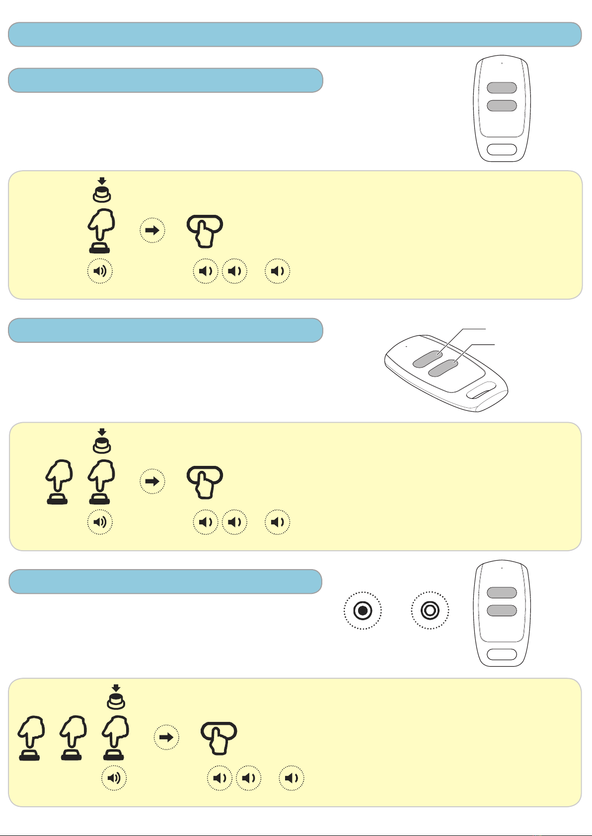
• Step 3: activation of the wireless safety device system
1- Push the button of the radio card (MASTER), L1 and L2 led will flash.
2- Push the button of the bottom slat transmitter (SLAVE). L2 led will turn on.
3- Exit pressing the button of the radio card (MASTER).
4- In case of correct memorization L2 will flash.
led
button
Check the system pressing the button of the bottom slat transmitter (SLAVE) and keeping it pressed:
- Slave led solid ON = OK
- Slave led flashing = No wireless communication
- Master L2 led must flash
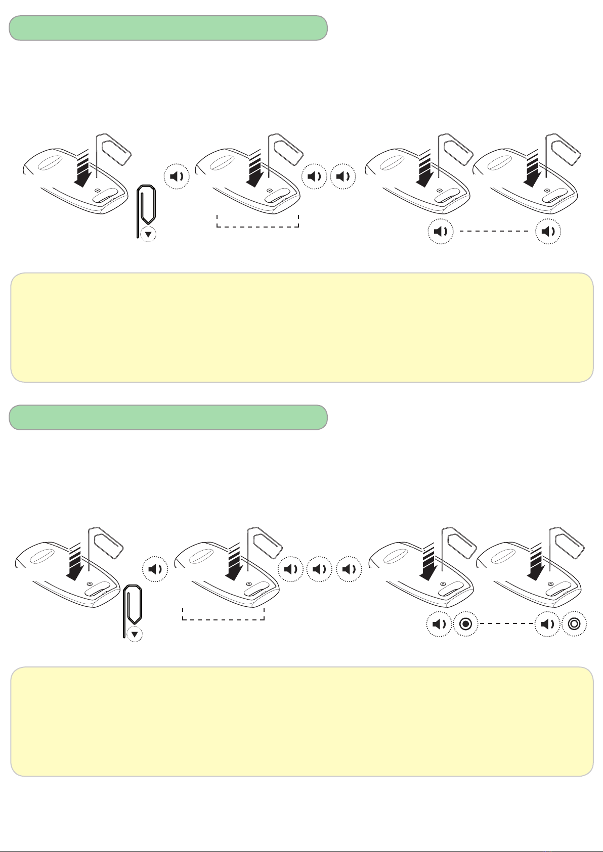
In case of problem, the system can be totally excluded with the procedure at page 10.
WARNING: the control unit executes a brief inversion of the movement (1 second) if any error occurs.
In case that the safety devices are defective or they have been activated, it is possible to operate the
door anyway, keeping pressed the command button for more than 5 seconds. The control unit will
automatically switch to hold-to-run mode.
Emergency STOP input (21-22) must be closed by a jumper if not used.
Check that TB led is ON (number 7 in the diagram at page 7).
In case of any problem, refer to the paragraph “Troubleshooting” at pages 17 and 18.
• Step 5: functioning mode
1 2 3
ON
1 2 3
ON
1 2 3
ON
DIP2 ON: AUTOMATIC mode.
OFF: HOLD-TO-RUN mode. Automatic opening and hold-to-run closing.
The automatic closure function is deactivated.
DIP3 ON: Automatic closure function activated. Default time is 5 sec.
This function has effect only when the door is totally open.
OFF: Automatic closure function deactivated (default setting).
1 2 3
ON
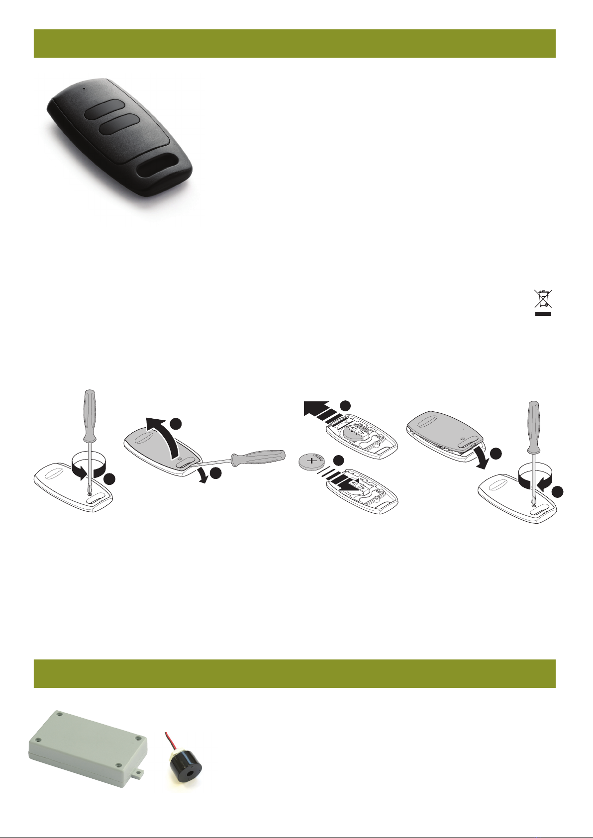
RADIO CARD
(MASTER)
SLAVE TRANSMITTER (TCSP)
1
ON
B2B1
2
++
P1
6 5 4 3
8K2
6 5 4 3
4- GREEN
5- BROWN
6- WHITE
3 4 5 6
BK2
Green
Brown
White
3 4 5 6
BK2
Green
Brown
White
P1
L3
L2
L1
L1 L2 L3
button