page 5 www.centsys.com
INTRODUCTIONSECTION 1
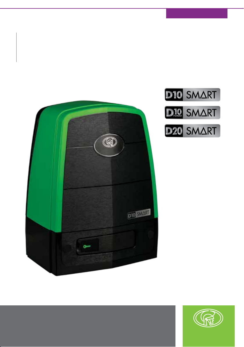
1. Introduction
The D10 SMART is a heavy duty sliding gate operator designed to open and close industrial
sliding gates weighing up to 1000Kg.
The D10 Turbo SMART is perfectly suited for sites with lighter gates requiring a high
number of operations per day, and can reach almost double the speed of the standard
D10 SMART for increased security. However, it is not suitable for gates weighing more than
250kg, as the inertia generated by heavier loads might prove detrimental to the gearbox
at such high speeds. Refer to Table 2 under Section
2.2. - "Technical Specications"
for
derating speeds on heavier gates.
A die-cast aluminium gearbox, coupled to a powerful 24V DC motor and switch-mode
charger, makes the D10 SMART / D10 Turbo SMART the automatic choice for townhouse
complexes and oce parks.
The system operates o two 12V / 7.2 - 8Ah batteries housed inside the operator using a
switch-mode charger to maintain the battery in a fully-charged state. The batteries provide
critical power failure protection.
A non-contact Hall Eect Sensor ensures reliability and positional accuracy. The Hall Eect
Sensor is highly resistant to dust, oil, dirt and insect ingress, thereby ensuring that the D10
SMART / D10 Turbo SMART opens and closes gates reliably and accurately.
For industrial sites with large, heavy gates and high trac volumes, the D20 SMART oers a
powerful and reliable automation solution that can move gates weighing up to 2000kg.
This formidable operator has been designed to withstand the most demanding operating
conditions and work dependably in any environment thanks to its rugged die-cast aluminium
gearbox and potent DC motor. In addition, its sophisticated electronics and motor control
circuitry ensure that it moves smoothly with pinpoint stopping, further adding to the unit’s
reliability and longevity. Complementing its tough mechanical build, award-winning SMART
technology makes the D20 SMART as intelligent as it is solid.
Advanced features of the D10 SMART / D10 Turbo SMART / D20 SMART logic
controller include:
• Interactive graphic user interface via a smartphone application
• Automated setup of gate endpoints (limits)
• Independently-adjustable motor speed in both opening and closing directions
• Fail-safe collision detection and auto reverse (adjustable sensitivity)
• Smooth, adjustable start/stop (ramp-up/ramp-down)
• Multiple operational modes
• Selectable, adjustable Autoclose
• Pedestrian (partial) opening
• Positive Close Mode
• Independent safety inputs for opening and closing beams
• Automatic beam test for both opening and closing beams
• Advanced lightning/surge protection
• Onboard NOVA code-hopping radio receiver with full channel-mapping capability
(Limited to 1500 NOVA remotes with multiple buttons per remote)